EP4114277B1 - Cadre de maintien d'écarteur chirurgical - Google Patents
Cadre de maintien d'écarteur chirurgical Download PDFInfo
- Publication number
- EP4114277B1 EP4114277B1 EP21715010.1A EP21715010A EP4114277B1 EP 4114277 B1 EP4114277 B1 EP 4114277B1 EP 21715010 A EP21715010 A EP 21715010A EP 4114277 B1 EP4114277 B1 EP 4114277B1
- Authority
- EP
- European Patent Office
- Prior art keywords
- retractor
- support body
- bore
- support frame
- annular hub
- Prior art date
- Legal status (The legal status is an assumption and is not a legal conclusion. Google has not performed a legal analysis and makes no representation as to the accuracy of the status listed.)
- Active
Links
Images



Classifications
-
- A—HUMAN NECESSITIES
- A61—MEDICAL OR VETERINARY SCIENCE; HYGIENE
- A61B—DIAGNOSIS; SURGERY; IDENTIFICATION
- A61B17/00—Surgical instruments, devices or methods
- A61B17/02—Surgical instruments, devices or methods for holding wounds open, e.g. retractors; Tractors
- A61B17/0218—Surgical instruments, devices or methods for holding wounds open, e.g. retractors; Tractors for minimally invasive surgery
-
- A—HUMAN NECESSITIES
- A61—MEDICAL OR VETERINARY SCIENCE; HYGIENE
- A61B—DIAGNOSIS; SURGERY; IDENTIFICATION
- A61B17/00—Surgical instruments, devices or methods
- A61B17/02—Surgical instruments, devices or methods for holding wounds open, e.g. retractors; Tractors
- A61B17/0206—Surgical instruments, devices or methods for holding wounds open, e.g. retractors; Tractors with antagonistic arms as supports for retractor elements
-
- A—HUMAN NECESSITIES
- A61—MEDICAL OR VETERINARY SCIENCE; HYGIENE
- A61B—DIAGNOSIS; SURGERY; IDENTIFICATION
- A61B90/00—Instruments, implements or accessories specially adapted for surgery or diagnosis and not covered by any of the groups A61B1/00 - A61B50/00, e.g. for luxation treatment or for protecting wound edges
- A61B90/50—Supports for surgical instruments, e.g. articulated arms
- A61B90/57—Accessory clamps
-
- A—HUMAN NECESSITIES
- A61—MEDICAL OR VETERINARY SCIENCE; HYGIENE
- A61B—DIAGNOSIS; SURGERY; IDENTIFICATION
- A61B17/00—Surgical instruments, devices or methods
- A61B2017/00477—Coupling
-
- A—HUMAN NECESSITIES
- A61—MEDICAL OR VETERINARY SCIENCE; HYGIENE
- A61B—DIAGNOSIS; SURGERY; IDENTIFICATION
- A61B17/00—Surgical instruments, devices or methods
- A61B2017/00526—Methods of manufacturing
-
- A—HUMAN NECESSITIES
- A61—MEDICAL OR VETERINARY SCIENCE; HYGIENE
- A61B—DIAGNOSIS; SURGERY; IDENTIFICATION
- A61B90/00—Instruments, implements or accessories specially adapted for surgery or diagnosis and not covered by any of the groups A61B1/00 - A61B50/00, e.g. for luxation treatment or for protecting wound edges
- A61B90/50—Supports for surgical instruments, e.g. articulated arms
Definitions
- the present invention relates generally to surgical retractors and more particularly, to a retractor frame holding assembly and related manufacturing methods involving the same.
- Open and mini-open surgical procedures require multiple instruments, e.g., for retracting and holding both instruments and the patient's tissue.
- soft tissue surgical procedures such as about the shoulder or hip, that require such an open or mini-open technique, as opposed to an arthroscopic technique.
- These open or mini-open procedures require expensive resources, including but not limited to additional staff surgeons and assistants to hold the various retraction and/or surgical instruments.
- US-A-2013/082157 describes a retractor ring assembly includes a ring holder that has a first selectively engaged connection and a second selectively engaged connection.
- a first and second ring portion each has a proximal end and a distal end. The proximal end of the first and second ring portions are selectively connected to the respective first and second selectively engaged connections of the ring holder.
- the distal end of the first ring portion has a third selectively engaged connection.
- the distal end of the second ring portion has a fourth selectively engaged connection.
- the third selectively engaged connection and the fourth selectively engaged connection are connectable to form a reinforced closed ring configuration, and are disconnectable to form an open ring configuration.
- US-A-2005/215865 describes a method of performing surgical retraction of flesh includes positioning a patient on a surgical table and making an incision into the flesh of the patient.
- a retractor support is mounted to the surgical table and positioned proximate the incision with a blade positioned within the incision and having a flexible member attached to the blade.
- the retractor blade is positioned manually to retract flesh.
- the flexible member in tension is attached to the retractor support thereby retracting the flesh and exposing the surgical site.
- a retractor holding frame is provided as defined by claim 1.
- a method of manufacturing a retractor holding frame is provided as defined by claim 14.
- Implementations of the technology described herein are directed generally to a retractor holding frame assembly and related methods.
- a specific method of measuring the characteristic or property may be defined herein as well.
- the measurement method should be interpreted as the method of measurement that would most likely be adopted by one of ordinary skill in the art given the description and context of the characteristic or property.
- the value or range of values should be interpreted as being met regardless of which method of measurement is chosen.
- any methods disclosed herein comprise one or more steps or actions for achieving the described method.
- the method steps and/or actions may be interchanged with one another without departing from the scope of the claims.
- the order and/or use of specific steps and/or actions may be modified without departing from the scope of the claims.
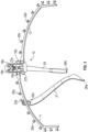
- FIG. 1 provides a left-side perspective view of retractor holding frame 10
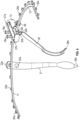
- FIGs. 3 and 4 provide center and right-side perspective views of retractor holding frame 10, respectively.
- Retractor holding frame 10 includes a left support frame arm 11 and a right support frame arm 12. Left and right support frame arms 11, 12 are each independently and adjustably supported by support body 13. Support body 13 is, in turn, adjustably supported from a surgical table by an adjustable support arm (not shown).
- support body 13 includes a first bore 14 extending transversely through support body 13 from a first side of support body 13 to a second side of support body 13 opposite the first side.
- Support body 13 also includes a second bore 15 extending transversely through support body 13 from the second side of support body 13 to the first side of support body 13.
- First bore 14 is configured to receive at least a portion of left support frame arm 11 at the first side of support body 13 and second bore 15 is configured to receive at least a portion of right support frame arm 12 at the second side of support body 13.
- left support frame arm 11 is provided with an annular hub 16a configured to be disposed in first bore 14 in support body 13.
- right support frame arm 12 in FIG. 6 right support frame arm 12 is provided with an annular hub 16b configured to be disposed in second bore 15 in support body 13.
- each of first and second bores 14, 15 and each of the respective first and second annular hubs 16a, 16b of left and right support frame arms 11, 12 have substantially circular cross-sections so as to allow respective annular hubs 16a, 16b of left and right support frame arms 11, 12 to fit and rotate within respective first and second bores 14, 15 of support body 13.
- each of first and second annular hubs 16a, 16b have respective tapered distal ends 27a, 27b, which allow for easy alignment and insertion of respective first and second annular hubs 16a, 16b into respective first and second bores 14, 15.
- each of first and second annular hubs 16a, 16b further include a respective annular series of recesses or detents 17a', 17b' configured to selectively receive a respective retaining pin 17a, 17b of a respective spring-biased locking mechanism 18a, 18b disposed on a top surface of support body 13.
- respective retaining pins 17a, 17b are configured to extend down into respective first and second bores 14, 15, under force provided by respective spring-biased locking mechanisms 18a, 18b, and seat and/or index within a respective one of the respective annular series of recesses or detents 17a', 17b' of respective hubs 16a, 16b.
- respective portions of spring-biased locking mechanisms 18a, 18b can be pulled upwardly to thereby retract respective retaining pins 17a, 17b sufficiently to allow respective annular hubs 16a, 16b of respective left and right support frame arms 11, 12 to be inserted into respective first and second bores 14, 15 and respective left and right support frame arms 11, 12 to be rotated to respective desired positions.
- Support body 13 is further provided with a quick-connect connector 28 for coupling support body 13 to a positioning arm (not shown) which, in turn, adjustably supports retractor holding frame 10 from a surgical table.
- a positioning arm (not shown) which, in turn, adjustably supports retractor holding frame 10 from a surgical table.
- a number of conventional positioning arms are available on the market.
- left and right support frame arms 11, 12 having any suitable shape.
- left and right support frame arms 11, 12 may have a substantially curved shape as illustrated in FIGs. 1 and 3-6 .
- one or both of left and right support frame arms 11, 12 could also and/or alternatively have a substantially straight shape, or one or more portions may have a substantially curved shape, while one or more other portions may have a substantially curved shape to suit the particular application.
- different sized and/or shaped left and right support frame arms 11, 12 may be readily substituted, inserted and/or removed from support body 13 as described above.
- Left and right support frame arms 11, 12 each further include a respective plurality of retaining hooks or posts 20a, 20b disposed along their outside edges and configured to receive and retain one or more retractors 21 in position.
- one or more retractors 21 may each be provided with a series of apertures 22a at a proximal end 23a and such apertures 22a are configured to receive one of hooks or posts 20a, 20b and thereby retain proximal ends 23a of retractors 21 on those respective hooks or posts 20a, 20b.
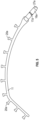
- Retractors 21 may have any suitable shape.
- retractors 21 may have at least one curved portion. For example, as illustrated in FIGs.
- proximal 23a and distal 26a ends of retractor 21 can be substantially curved.
- retractors 21 may have at least one substantially straight portion.
- a medial portion of retractor 21 can be substantially straight.
- at least a portion of retractor 21 can be tapered.
- retractor 21 can taper along its length of extension at least from its medial portion to distal end 26a. Such a tapered aspect may allow retractors 21 to more effectively focus retention force to a particular portion of a patient's tissue. It should also be appreciated that, while the figures illustrate one retractor 21 disposed on left support frame arm 11, one or more retractors 21 can also or alternatively be similarly disposed on right support frame 12.
- an underside of support body 13 can further include one or more hooks or posts 24 configured to receive and retain in position one or more additional retractors 25.
- one or more additional retractors 25 can each be provided with a similar series of apertures 22b at a similar proximal end 23b of additional retractors 25, and such apertures 22b of additional retractors 25 are configured to receive one of hooks or posts 24 on underside of support body 13 and thereby retain proximal end(s) 23b of additional retractor(s) 25 on respective hooks or posts 24.
- retractors 25 may have any suitable shape.
- retractors 25 may have at least one curved portion. For example, as illustrated in FIGs.
- proximal 23b and distal 26b ends of retractor 25 can be substantially curved.
- retractors 25 may have at least one substantially straight portion.
- a medial portion of retractor 25 can be substantially straight.
- at least a portion of retractor 25 can be tapered.
- retractor 25 can taper along its length of extension at least from its medial portion to distal end 26b. Such a tapered aspect may allow retractors 25 to more effectively focus retention force to a particular portion of a patient's tissue.
- respective distal ends 26a, 26b of retractors 21, 25 may be adjustably positioned to retain and spread patient tissue at an incision made at a surgical access point on the patient. This allows the surgeon to securely place and hold a set of retractors 21, 25 during a surgical procedure without the need for additional surgical staff.
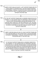
- FIG. 7 illustrates a flowchart 700 corresponding to such a method of use, in accordance with embodiments which do not form part of the invention. While flowchart 700 illustrates one or more actions and/or steps, it should be understood that one or more described actions can be omitted, one or more additional or alternative actions can be added, and/or one or more actions can be performed in another order than that specifically described without departing from the scope of the present disclosure.
- Block 702 includes inserting a first annular hub of a left support frame arm into a first bore of a support body, the first bore extending transversely through the support body from a first side of the support body to a second side of the support body opposite the first side.
- first annular hub 16a of left support frame arm 11 can be inserted into first bore 14 of support body 13.
- First bore 14 extends transversely through support body 13 from a first side of support body 13 to a second side of support body 13 opposite the first side.
- inserting the first annular hub of the left support frame arm into the first bore of the support body includes utilizing at least a portion of first spring-biased locking mechanism 18a to retract first retaining pin 17a sufficiently from first bore 14 to allow annular hub 16a of left support frame arm 11 to be inserted into first bore 14.
- first annular hub 16a has a tapered distal end 27a configured to aid alignment between first annular hub 16a and first bore 14.
- Block 704 includes fixing the left support frame arm in a desired orientation with respect to the support body by disposing a first retaining pin of a first spring-biased locking mechanism of the support body down into the first bore such that the first retaining pin is received into one of a first annular series of detents disposed in the first annular hub of the left support frame arm.
- left support frame arm 11 can be fixed in a desired orientation with respect to support body 13 by disposing first retaining pin 17a of first spring-biased locking mechanism 18a of support body 13 down into first bore 14 such that first retaining pin 17a is received into one of a first annular series of detents 17a' disposed in annular hub 16a of left support frame arm 11.
- fixing the left support frame arm in the desired orientation with respect to the support body includes first rotating left support frame arm 11 to the desired orientation while its annular hub 16a is disposed within first bore 14 and first retaining pin 17a is retracted from first bore 14.
- left support frame arm 11 further comprises first plurality of posts 20a disposed along an outer edge of left support frame arm 11.
- flowchart 700 may further include securing one of a series of apertures 22a, disposed at a proximal end 23a of a first retractor 21, to one of the first plurality of posts 20a of left support frame arm 11 to thereby retain first retractor 21 in a first desired orientation.
- Block 706 includes inserting a second annular hub of a right support frame arm into a second bore of the support body, the second bore extending transversely through the support body from the second side to the first side.
- annular hub 16b of right support frame arm 12 can be inserted into second bore 15 of support body 13.
- Second bore 15 extends transversely through support body 13 from the second side of support body 13 to the first side of support body 13.
- inserting the second annular hub of the right support frame arm into the second bore of the support body includes utilizing at least a portion of second spring-biased locking mechanism 18b to retract second retaining pin 17b sufficiently from second bore 15 to allow annular hub 16b of right support frame arm 12 to be inserted into second bore 15.
- second annular hub 16b has a tapered distal end 27b configured to aid alignment between second annular hub 16b and second bore 15.
- Block 708 includes fixing the right support frame arm in a desired orientation with respect to the support body by disposing a second retaining pin of a second spring-biased locking mechanism of the support body down into the second bore such that the second retaining pin is received into one of a second annular series of detents disposed in the second annular hub of the right support frame arm.
- right support frame arm 12 can be fixed in a desired orientation with respect to support body 13 by disposing second retaining pin 17a of second spring-biased locking mechanism 18b of support body 13 down into second bore 15 such that second retaining pin 17b is received into one of a second annular series of detents 17b' disposed in annular hub 16b of right support frame arm 12.
- fixing the right support frame arm in the desired orientation with respect to the support body includes first rotating right support frame arm 12 to the desired orientation while its annular hub 16b is disposed within second bore 15 and second retaining pin 17b is retracted from second bore 15.
- an underside of support body 13 further comprises at least one post 24 and flowchart 700 can further include securing one of a series of apertures 22b, disposed at a proximal end 23b of an additional retractor 25, to one of the at least one post 24 on the underside of support body 13 to thereby retain additional retractor 25 in an additional desired orientation.
- each of the first and second annular hubs 16a, 16b, first bore 14 and second bore 15 have a circular cross-section, thereby allowing the first annular hub 16ab to rotate within first bore 14 and left support frame arm 11 to rotate with respect to support body 13 and thereby allowing the second annular hub 16b to rotate within second bore 15 and right support frame arm 12 to rotate with respect to support body 13.
- support body 13 further includes quick-connect connector 28 and flowchart 700 can further include coupling support body 13 to a positioning arm utilizing quick-connect connector 28.
- at least one respective portion of each of left and right support frame arms 11,12 has a curved shape.
- at least one respective portion of each of left and right support frame arms 11, 12 has a substantially straight shape.
- at least one of first and second retractors 21 taper along their respective lengths.
- first and second retractors 21 each comprise at least one curved portion.
- FIG. 8 illustrates a flowchart 800 corresponding to such a method of manufacture, in accordance with the invention. While flowchart 800 illustrates one or more actions and/or steps, it should be understood that one or more described actions can be omitted, one or more additional or alternative actions can be added, and/or one or more actions can be performed in another order than that specifically described without departing from the scope of the present disclosure.
- Block 802 includes providing a support body having a first side and a second side opposite the first side.
- a support body having a first side and a second side opposite the first side.
- Block 804 includes forming a first bore extending transversely through the support body from the first side to the second side.
- first bore 14 is formed to extend transversely through support body 13 from a first side of support body 13 to a second side of support body 13 opposite the first side.
- Block 806 includes forming a second bore extending transversely through the support body from the second side to the first side.
- second bore 15 extends transversely through support body 13 from the second side of support body 13 to the first of support body 13.
- Block 808 includes providing a left support frame arm comprising a first annular hub configured to be disposed within the first bore of the support body, and a first plurality of posts disposed along an outer edge of the left support frame arm and configured to receive and retain at least a first retractor in a first desired orientation.
- left support frame arm 11 is provided including annular hub 16a configured to be disposed within first bore 14 of support body 13, and a first plurality of posts 20a disposed along an outer edge of left support frame arm 11 and configured to receive and retain at least a first retractor 21 in a first desired orientation.
- Block 810 includes providing a right support frame arm comprising a second annular hub configured to be disposed within the second bore of the support body, and a second plurality of posts disposed along an outer edge of the right support frame arm and configured to receive and retain at least a second retractor in a second desired orientation.
- right support frame arm 12 is provided including annular hub 16b configured to be disposed within second bore 15 of support body 13, and a second plurality of posts 20b disposed along an outer edge of right support frame arm 12 and configured to receive and retain at least a second retractor 21 in a second desired orientation.
- each of first and second annular hubs 16a, 16b, first bore 14 and second bore 15 are formed to have a circular cross-section, thereby allowing the first annular hub 16a to rotate within first bore 14 and left support frame arm 11 to rotate with respect to support body 13 and thereby allowing the second annular hub 16b to rotate within second bore 15 and right support frame arm 12 to rotate with respect to support body 13.
- flowchart 800 can further include disposing at least one post 24 on an underside of support body 13 such that the at least one post 24 is configured to receive and retain at least one additional retractor 25 in an additional desired orientation.
- flowchart 800 can further include forming a tapered distal end 27a on first annular hub 16a to aid alignment between first annular hub 16a and first bore 14. In some embodiments, flowchart 800 can further include forming a tapered distal end 27b on the second annular hub 16b to aid alignment between second annular hub 16b and second bore 15.
- flowchart 800 further includes providing a first spring-biased locking mechanism 18a, including a first retaining pin 17a configured to extend down into first bore 14, on support body 13.
- providing the first spring-biased locking mechanism includes providing at least a portion of the first spring-biased locking mechanism 18a that is configured to retract the first retaining pin 17a sufficiently from first bore 14 to allow first annular hub 16a to be inserted into first bore 14 or left support frame arm 11 to be rotated with respect to support body 13 while first annular hub 16a is disposed within first bore 14.
- flowchart 800 further includes providing second spring-biased locking mechanism 18b, including second retaining pin 17b configured to extend down into second bore 15, on support body 13.
- providing second spring-biased locking mechanism 18b includes providing at least a portion of second spring-biased locking mechanism 18b that is configured to retract second retaining pin 17b sufficiently from second bore 15 to allow second annular hub 16b to be inserted into second bore 15 or right support frame arm 12 to be rotated with respect to support body 13 while second annular hub 16b is disposed within second bore 15.
- flowchart 800 further includes forming a first annular series of detents 17a' in first annular hub 16a configured to selectively receive first retaining pin 17a and thereby fix left support frame arm 11 in a desired orientation with respect to support body 13.
- Flowchart 800 further includes forming a second annular series of detents 17b' in second annular hub 16b configured to selectively receive second retaining pin 17b and thereby fix right support frame arm 12 in a desired orientation with respect to support body 13.
- flowchart 800 can further include securing quick-connect connector 28 to support body 13, quick-connect connector 28 being configured to couple support body 13 to a positioning arm.
- At least one respective portion of each of left and right support frame arms 11, 12 has a curved shape. In some embodiments, at least one respective portion of each of left and right support frame arms 11, 12 has a substantially straight shape.
- flowchart 800 can further include providing the first retractor 21 having a series of apertures 22a disposed at proximal end 23b thereof, the series of apertures 22a configured to receive a post of first plurality of posts 20b of left support frame arm 11 and thereby retain proximal end 23a of first retractor 21 thereon.
- flowchart 800 can further include providing the second retractor 21 having a series of apertures 22a disposed at a proximal end 23a thereof, the series of apertures 22a configured to receive a post of the second plurality of posts 20b of right support frame arm 12 and thereby retain proximal end 23a of second retractor 21 thereon.
- flowchart 800 can further include providing the additional retractor 25 having a series of apertures 22b disposed at a proximal end 23b thereof, the series of apertures 22b configured to receive the at least one post 24 on the underside of support body 13 and thereby retain proximal end 23b of additional retractor 25 thereon.
- At least one of the first and second retractors 21 tapers along their respective lengths. In some embodiments, the first and second retractors 21 each comprise at least one curved portion.
Landscapes
- Health & Medical Sciences (AREA)
- Life Sciences & Earth Sciences (AREA)
- Surgery (AREA)
- Molecular Biology (AREA)
- Engineering & Computer Science (AREA)
- Biomedical Technology (AREA)
- Heart & Thoracic Surgery (AREA)
- Medical Informatics (AREA)
- Nuclear Medicine, Radiotherapy & Molecular Imaging (AREA)
- Animal Behavior & Ethology (AREA)
- General Health & Medical Sciences (AREA)
- Public Health (AREA)
- Veterinary Medicine (AREA)
- Oral & Maxillofacial Surgery (AREA)
- Pathology (AREA)
- Surgical Instruments (AREA)
Claims (15)
- Cadre de maintien d'écarteur (10), comprenant :un corps de support (13), comprenant :un premier alésage (14) s'étendant transversalement à travers le corps de support depuis un premier côté du corps de support vers un second côté du corps de support opposé au premier côté,un second alésage (15) s'étendant transversalement à travers le corps de support depuis le second côté vers le premier côté,un bras de cadre de support gauche (11) comprenant :un premier moyeu annulaire (16a) configuré pour être disposé à l'intérieur du premier alésage du corps de support,une première pluralité de montants (20a) disposés le long d'un bord extérieur du bras de cadre de support gauche et configurés pour recevoir et retenir au moins un premier écarteur (21) dans une première orientation,
etun bras de cadre de support droit (12) comprenant :un second moyeu annulaire (16b) configuré pour être disposé à l'intérieur du second alésage du corps de support,une seconde pluralité de montants (20b) disposés le long d'un bord extérieur du bras de cadre de support droit et configurés pour recevoir et retenir au moins un second écarteur (21) dans une deuxième orientation,caractérisé en ce quele corps de support comprend en outre :un premier mécanisme de verrouillage sollicité par ressort (18a) incluant une première broche de retenue (17a) configurée pour s'étendre vers le bas dans le premier alésage, etun second mécanisme de verrouillage sollicité par ressort (18b) comprenant une seconde broche de retenue (17b) configurée pour s'étendre vers le bas dans le second alésage ;le bras de cadre de support gauche comprend une première série annulaire de crans (17a') configurés pour recevoir de manière sélective la première broche de retenue et ainsi fixer le cadre de support gauche dans une orientation souhaitée par rapport au corps de support ; etle bras de cadre de support droit comprend une seconde série annulaire de crans (17b') configurés pour recevoir sélectivement la seconde broche de retenue et ainsi fixer le cadre de support droit dans une orientation souhaitée par rapport au corps de support. - Cadre de maintien d'écarteur selon la revendication 1, dans lequel une face inférieure du corps de support comprend en outre au moins un montant (24) configuré pour recevoir et retenir au moins un écarteur supplémentaire (25) dans une troisième orientation.
- Écarteur selon la revendication 1, dans lequel chacun du premier moyeu annulaire, du second moyeu annulaire, du premier alésage et du second alésage présente une section transversale circulaire, en permettant ainsi au premier moyeu annulaire de tourner dans le premier alésage et au bras de cadre de support gauche de tourner par rapport au corps de support, et en permettant ainsi au second moyeu annulaire de tourner dans le second alésage et au bras de cadre de support droit de tourner par rapport au corps de support.
- Cadre de maintien d'écarteur selon la revendication 1, dans lequel :le premier moyeu annulaire présente une extrémité distale effilée (27a) configurée pour faciliter un alignement entre le premier moyeu annulaire et le premier alésage ; etle second moyeu annulaire présente une extrémité distale effilée (27b) configurée pour faciliter un alignement entre le second moyeu annulaire et le second alésage.
- Cadre de maintien d'écarteur selon la revendication 1, dans lequel :au moins une partie du premier mécanisme de verrouillage sollicité par ressort est configurée pour rétracter suffisamment la première broche de retenue à partir du premier alésage afin de permettre au premier moyeu annulaire d'être inséré dans le premier alésage ou au bras de cadre de support gauche d'être tourné par rapport au corps de support tandis que le premier moyeu annulaire est disposé à l'intérieur du premier alésage ; etau moins une partie du second mécanisme de verrouillage sollicité par ressort est configurée pour rétracter suffisamment la seconde broche de retenue à partir du second alésage pour permettre au second moyeu annulaire d'être inséré dans le second alésage ou au bras de cadre de support droit d'être tourné par rapport au corps de support tandis que le second moyeu annulaire est disposé à l'intérieur du second alésage.
- Cadre de maintien d'écarteur selon la revendication 1, dans lequel le corps de support comprend en outre un connecteur à connexion rapide (28) configuré pour coupler le corps de support à un bras de positionnement.
- Cadre de maintien d'écarteur selon la revendication 1, dans lequel au moins une partie respective de chacun des bras de cadre de support gauche et droit présente une forme incurvée.
- Cadre de maintien d'écarteur selon la revendication 1, dans lequel au moins une partie respective de chacun des bras de cadre de support gauche et droit présente une forme sensiblement droite.
- Cadre de maintien d'écarteur selon la revendication 1, comprenant en outre le premier écarteur, dans lequel le premier écarteur comprend une première série d'ouvertures (22a) disposées au niveau d'une extrémité proximale (23a) du premier écarteur et configurées pour recevoir un montant de la première pluralité de montants du bras de cadre de support gauche et ainsi retenir l'extrémité proximale du premier écarteur sur celui-ci.
- Cadre de maintien d'écarteur selon la revendication 9, comprenant en outre un second écarteur (21), dans lequel le second écarteur comprend une seconde série d'ouvertures (22a) disposées à une extrémité proximale (23a) du second écarteur et configurées pour recevoir un montant de la seconde pluralité de montants du bras de cadre de support droit et ainsi retenir l'extrémité proximale du second écarteur sur celui-ci.
- Cadre de maintien d'écarteur selon la revendication 2, comprenant en outre l'écarteur supplémentaire, dans lequel l'écarteur supplémentaire comprend une série supplémentaire d'ouvertures (22b) disposées au niveau d'une extrémité proximale (23b) de l'écarteur supplémentaire et configurées pour recevoir le au moins un montant sur la face inférieure du corps de support et ainsi retenir l'extrémité proximale de l'écarteur supplémentaire sur celui-ci.
- Cadre de maintien d'écarteur selon la revendication 10, dans lequel au moins l'un des premier et second écarteurs est effilé le long de leurs longueurs respectives.
- Cadre de maintien d'écarteur selon la revendication 10, dans lequel les premier et second écarteurs comprennent chacun au moins une partie incurvée.
- Procédé de fabrication d'un cadre de maintien d'écarteur (10), le procédé comprenant les étapes consistant à :fournir un corps de support (13) comprenant un premier côté et un second côté opposé au premier côté ;former un premier alésage (14) s'étendant transversalement à travers le corps de support depuis le premier côté vers le second côté ;former un second alésage (15) s'étendant transversalement à travers le corps de support depuis le second côté vers le premier côté ;fournir un bras de cadre de support gauche (11) comprenant :un premier moyeu annulaire (16a) configuré pour être disposé à l'intérieur du premier alésage du corps de support, etune première pluralité de montants (20a) disposés le long d'un bord extérieur du bras de cadre de support gauche et configurés pour recevoir et retenir au moins un premier écarteur (21) dans une première orientation ;fournir un bras de cadre de support droit (12) comprenant :un second moyeu annulaire (16b) configuré pour être disposé à l'intérieur du second alésage du corps de support, etune seconde pluralité de montants (20b) disposés le long d'un bord extérieur du bras de cadre de support droit et configurés pour recevoir et retenir au moins un second écarteur (21) dans une deuxième orientation ; caractérisé en ce que le procédé comprend en outre les étapes consistant à :fournir un premier mécanisme de verrouillage sollicité par ressort (18a), comprenant une première broche de retenue (17a) configurée pour s'étendre vers le bas dans le premier alésage, sur le corps de support ;fournir un second mécanisme de verrouillage sollicité par ressort (18b), comprenant une seconde broche de retenue (17b) configurée pour s'étendre vers le bas dans le second alésage, sur le corps de support ;former une première série annulaire de crans (17a') dans le premier moyeu annulaire, configurés pour recevoir sélectivement la première broche de retenue et ainsi fixer le bras de cadre de support gauche dans une orientation souhaitée par rapport au corps de support ; etformer une seconde série annulaire de crans (17b') dans le second moyeu annulaire, configurés pour recevoir sélectivement la seconde broche de retenue et ainsi fixer le bras de cadre de support droit dans une orientation souhaitée par rapport au corps de support.
- Procédé selon la revendication 14, comprenant en outre l'étape consistant à disposer au moins un montant (24) sur une face inférieure du corps de support de telle sorte que le au moins un montant soit configuré pour recevoir et retenir au moins un écarteur supplémentaire (25) dans une troisième orientation.
Priority Applications (1)
| Application Number | Priority Date | Filing Date | Title |
|---|---|---|---|
| EP24211542.6A EP4559408A3 (fr) | 2020-03-03 | 2021-03-02 | Cadre de maintien d'écarteur chirurgical |
Applications Claiming Priority (2)
| Application Number | Priority Date | Filing Date | Title |
|---|---|---|---|
| US202062984363P | 2020-03-03 | 2020-03-03 | |
| PCT/US2021/020400 WO2021178365A1 (fr) | 2020-03-03 | 2021-03-02 | Cadre de maintien d'écarteur chirurgical |
Related Child Applications (2)
| Application Number | Title | Priority Date | Filing Date |
|---|---|---|---|
| EP24211542.6A Division EP4559408A3 (fr) | 2020-03-03 | 2021-03-02 | Cadre de maintien d'écarteur chirurgical |
| EP24211542.6A Division-Into EP4559408A3 (fr) | 2020-03-03 | 2021-03-02 | Cadre de maintien d'écarteur chirurgical |
Publications (2)
| Publication Number | Publication Date |
|---|---|
| EP4114277A1 EP4114277A1 (fr) | 2023-01-11 |
| EP4114277B1 true EP4114277B1 (fr) | 2024-12-25 |
Family
ID=75267583
Family Applications (2)
| Application Number | Title | Priority Date | Filing Date |
|---|---|---|---|
| EP21715010.1A Active EP4114277B1 (fr) | 2020-03-03 | 2021-03-02 | Cadre de maintien d'écarteur chirurgical |
| EP24211542.6A Pending EP4559408A3 (fr) | 2020-03-03 | 2021-03-02 | Cadre de maintien d'écarteur chirurgical |
Family Applications After (1)
| Application Number | Title | Priority Date | Filing Date |
|---|---|---|---|
| EP24211542.6A Pending EP4559408A3 (fr) | 2020-03-03 | 2021-03-02 | Cadre de maintien d'écarteur chirurgical |
Country Status (7)
| Country | Link |
|---|---|
| US (2) | US11395646B2 (fr) |
| EP (2) | EP4114277B1 (fr) |
| JP (1) | JP7466668B2 (fr) |
| KR (1) | KR102913166B1 (fr) |
| AU (1) | AU2021229480B2 (fr) |
| ES (1) | ES3014369T3 (fr) |
| WO (1) | WO2021178365A1 (fr) |
Families Citing this family (2)
| Publication number | Priority date | Publication date | Assignee | Title |
|---|---|---|---|---|
| EP4114277B1 (fr) * | 2020-03-03 | 2024-12-25 | Encore Medical, L.P. dba DJO Surgical | Cadre de maintien d'écarteur chirurgical |
| WO2023199347A1 (fr) * | 2022-04-10 | 2023-10-19 | Dessinrx Healthcare Pvt. Ltd | Dispositif écarteur de lambeaux cutanés |
Family Cites Families (19)
| Publication number | Priority date | Publication date | Assignee | Title |
|---|---|---|---|---|
| US3509873A (en) * | 1967-04-24 | 1970-05-05 | Jack B Karlin | Retractor |
| US4949707A (en) * | 1984-11-08 | 1990-08-21 | Minnesota Scientific, Inc. | Retractor apparatus |
| US5897087A (en) * | 1994-03-15 | 1999-04-27 | Thompson Surgical Instruments, Inc. | CAM tightened universal joint clamp |
| US5899627A (en) * | 1996-09-12 | 1999-05-04 | Minnesota Scientific, Inc. | Clamp for retractor support |
| US6663563B1 (en) * | 1998-10-02 | 2003-12-16 | Minnesota Scientific, Inc. | Fastening system for retractor support |
| US6659945B2 (en) * | 2001-06-29 | 2003-12-09 | Depuy Orthopaedics, Inc. | Self retaining retractor ring |
| US6790177B2 (en) * | 2002-06-27 | 2004-09-14 | Boss Instruments, Ltd. | Surgical retractor apparatus |
| EP1551276A4 (fr) * | 2002-07-18 | 2008-07-16 | Minnesota Scientific Inc | Procede et appareil de remplacement d'articulation du genou |
| US20050215865A1 (en) * | 2002-07-18 | 2005-09-29 | Minnesota Scientific, Inc. | Method and apparatus for surgical retraction |
| US7125379B2 (en) * | 2003-09-19 | 2006-10-24 | Minnesota Scientific, Inc. | Surgical support arm docking apparatus |
| US20070213597A1 (en) * | 2006-03-01 | 2007-09-13 | Wooster Nicholas H | Surgical retractor frame system |
| WO2008055324A2 (fr) * | 2006-11-07 | 2008-05-15 | Stanislav Nestorov | Dispositif de serrage et système rétracteur utilisant ce dernier |
| US8894029B2 (en) * | 2011-09-30 | 2014-11-25 | Specialty Surgical Instrumentation, Inc. | Retractor ring holder |
| CN103987327A (zh) * | 2011-10-05 | 2014-08-13 | 马克·A·多德森 | 模块化牵开器及相关方法 |
| US9078635B2 (en) * | 2012-02-02 | 2015-07-14 | Tedan Surgical Innovations, Llc | Anterior hip replacement retractor assembly |
| US10786328B2 (en) * | 2016-10-26 | 2020-09-29 | Thompson Surgical Instruments, Inc. | Adaptor handle for surgical retractor |
| US10772704B2 (en) * | 2018-03-12 | 2020-09-15 | Zimmer Biomet CMF and Thoracic, LLC | End effector coupler for surgical arm |
| MX2021003165A (es) * | 2018-09-17 | 2021-09-23 | Ramon Francisco Cestero | Retractor quirurgico de bloqueo ajustable. |
| EP4114277B1 (fr) * | 2020-03-03 | 2024-12-25 | Encore Medical, L.P. dba DJO Surgical | Cadre de maintien d'écarteur chirurgical |
-
2021
- 2021-03-02 EP EP21715010.1A patent/EP4114277B1/fr active Active
- 2021-03-02 AU AU2021229480A patent/AU2021229480B2/en active Active
- 2021-03-02 US US17/189,549 patent/US11395646B2/en active Active
- 2021-03-02 WO PCT/US2021/020400 patent/WO2021178365A1/fr not_active Ceased
- 2021-03-02 ES ES21715010T patent/ES3014369T3/es active Active
- 2021-03-02 KR KR1020227030079A patent/KR102913166B1/ko active Active
- 2021-03-02 EP EP24211542.6A patent/EP4559408A3/fr active Pending
- 2021-03-02 JP JP2022549102A patent/JP7466668B2/ja active Active
-
2022
- 2022-07-22 US US17/871,062 patent/US12226089B2/en active Active
Also Published As
| Publication number | Publication date |
|---|---|
| JP7466668B2 (ja) | 2024-04-12 |
| JP2023516563A (ja) | 2023-04-20 |
| ES3014369T3 (en) | 2025-04-22 |
| AU2021229480A1 (en) | 2022-09-22 |
| EP4559408A2 (fr) | 2025-05-28 |
| US20210275159A1 (en) | 2021-09-09 |
| KR20220134620A (ko) | 2022-10-05 |
| WO2021178365A1 (fr) | 2021-09-10 |
| US12226089B2 (en) | 2025-02-18 |
| US20230000479A1 (en) | 2023-01-05 |
| EP4559408A3 (fr) | 2025-07-23 |
| AU2021229480B2 (en) | 2023-11-23 |
| KR102913166B1 (ko) | 2026-01-15 |
| EP4114277A1 (fr) | 2023-01-11 |
| US11395646B2 (en) | 2022-07-26 |
Similar Documents
| Publication | Publication Date | Title |
|---|---|---|
| JP4717828B2 (ja) | 外科用開創器、照明カニューレ、および使用法 | |
| US12226089B2 (en) | Surgical tissue retractor holding frame | |
| US6511423B2 (en) | Cross bar for a surgical retractor system | |
| EP1534153B1 (fr) | Guide pour dispositif medical | |
| JP4248631B2 (ja) | 手術器具支持装置 | |
| TWI508703B (zh) | 用於診斷、介入、治療的磁共振斷層掃描儀局部線圈裝置 | |
| CN102160808B (zh) | 可扩展的胸腔进入口 | |
| WO2000015132A3 (fr) | Appareil pour chirurgie stereotaxique sans cadre | |
| EP1269922A1 (fr) | Support articulé et verrouillable pour les sutures et écarteurs chirurgicaux | |
| US20090018401A1 (en) | Surgical retractor positioning device | |
| CN104720882A (zh) | 杆插入装置 | |
| JPH11505152A (ja) | 切断ガイド器具 | |
| US20120053573A1 (en) | Surgical Apparatus | |
| CZ288799B6 (cs) | Způsob vedení vrtacího nástroje v průběhu vrtání podélného otvoru skrze krček lidské stehenní kosti a nástroj k provádění tohoto způsobu | |
| US20050171405A1 (en) | Surgical retractor with intermediate support members | |
| AU2015225580B2 (en) | Separable guide instrument for anatomical implant | |
| US20230380827A1 (en) | Retractor System | |
| US20130046353A1 (en) | Oval tunnel dilators | |
| US7195589B1 (en) | Pressure relief pad for use with a circumferential retractor | |
| US20220240904A1 (en) | Adjustable transperineal biopsy needle guide | |
| CA2884600A1 (fr) | Bloc de coupe de femur distal et son procede d'utilisation | |
| CN221533700U (zh) | 一种双通道内窥镜 | |
| CN112057130B (zh) | 一种可调节血管固定器 | |
| RU206163U1 (ru) | Ранорасширитель нейрохирургический | |
| CN219645858U (zh) | 股骨颈空心螺钉万向导向器 |
Legal Events
| Date | Code | Title | Description |
|---|---|---|---|
| STAA | Information on the status of an ep patent application or granted ep patent |
Free format text: STATUS: UNKNOWN |
|
| STAA | Information on the status of an ep patent application or granted ep patent |
Free format text: STATUS: THE INTERNATIONAL PUBLICATION HAS BEEN MADE |
|
| PUAI | Public reference made under article 153(3) epc to a published international application that has entered the european phase |
Free format text: ORIGINAL CODE: 0009012 |
|
| STAA | Information on the status of an ep patent application or granted ep patent |
Free format text: STATUS: REQUEST FOR EXAMINATION WAS MADE |
|
| 17P | Request for examination filed |
Effective date: 20220810 |
|
| AK | Designated contracting states |
Kind code of ref document: A1 Designated state(s): AL AT BE BG CH CY CZ DE DK EE ES FI FR GB GR HR HU IE IS IT LI LT LU LV MC MK MT NL NO PL PT RO RS SE SI SK SM TR |
|
| DAV | Request for validation of the european patent (deleted) | ||
| DAX | Request for extension of the european patent (deleted) | ||
| P01 | Opt-out of the competence of the unified patent court (upc) registered |
Effective date: 20230822 |
|
| GRAP | Despatch of communication of intention to grant a patent |
Free format text: ORIGINAL CODE: EPIDOSNIGR1 |
|
| STAA | Information on the status of an ep patent application or granted ep patent |
Free format text: STATUS: GRANT OF PATENT IS INTENDED |
|
| INTG | Intention to grant announced |
Effective date: 20240718 |
|
| GRAS | Grant fee paid |
Free format text: ORIGINAL CODE: EPIDOSNIGR3 |
|
| GRAA | (expected) grant |
Free format text: ORIGINAL CODE: 0009210 |
|
| STAA | Information on the status of an ep patent application or granted ep patent |
Free format text: STATUS: THE PATENT HAS BEEN GRANTED |
|
| AK | Designated contracting states |
Kind code of ref document: B1 Designated state(s): AL AT BE BG CH CY CZ DE DK EE ES FI FR GB GR HR HU IE IS IT LI LT LU LV MC MK MT NL NO PL PT RO RS SE SI SK SM TR |
|
| REG | Reference to a national code |
Ref country code: GB Ref legal event code: FG4D |
|
| REG | Reference to a national code |
Ref country code: CH Ref legal event code: EP |
|
| REG | Reference to a national code |
Ref country code: DE Ref legal event code: R096 Ref document number: 602021023862 Country of ref document: DE |
|
| REG | Reference to a national code |
Ref country code: IE Ref legal event code: FG4D |
|
| REG | Reference to a national code |
Ref country code: LT Ref legal event code: MG9D |
|
| PG25 | Lapsed in a contracting state [announced via postgrant information from national office to epo] |
Ref country code: HR Free format text: LAPSE BECAUSE OF FAILURE TO SUBMIT A TRANSLATION OF THE DESCRIPTION OR TO PAY THE FEE WITHIN THE PRESCRIBED TIME-LIMIT Effective date: 20241225 |
|
| PG25 | Lapsed in a contracting state [announced via postgrant information from national office to epo] |
Ref country code: FI Free format text: LAPSE BECAUSE OF FAILURE TO SUBMIT A TRANSLATION OF THE DESCRIPTION OR TO PAY THE FEE WITHIN THE PRESCRIBED TIME-LIMIT Effective date: 20241225 |
|
| PG25 | Lapsed in a contracting state [announced via postgrant information from national office to epo] |
Ref country code: BG Free format text: LAPSE BECAUSE OF FAILURE TO SUBMIT A TRANSLATION OF THE DESCRIPTION OR TO PAY THE FEE WITHIN THE PRESCRIBED TIME-LIMIT Effective date: 20241225 |
|
| REG | Reference to a national code |
Ref country code: ES Ref legal event code: FG2A Ref document number: 3014369 Country of ref document: ES Kind code of ref document: T3 Effective date: 20250422 |
|
| PG25 | Lapsed in a contracting state [announced via postgrant information from national office to epo] |
Ref country code: NO Free format text: LAPSE BECAUSE OF FAILURE TO SUBMIT A TRANSLATION OF THE DESCRIPTION OR TO PAY THE FEE WITHIN THE PRESCRIBED TIME-LIMIT Effective date: 20250325 |
|
| PG25 | Lapsed in a contracting state [announced via postgrant information from national office to epo] |
Ref country code: GR Free format text: LAPSE BECAUSE OF FAILURE TO SUBMIT A TRANSLATION OF THE DESCRIPTION OR TO PAY THE FEE WITHIN THE PRESCRIBED TIME-LIMIT Effective date: 20250326 Ref country code: LV Free format text: LAPSE BECAUSE OF FAILURE TO SUBMIT A TRANSLATION OF THE DESCRIPTION OR TO PAY THE FEE WITHIN THE PRESCRIBED TIME-LIMIT Effective date: 20241225 |
|
| PGFP | Annual fee paid to national office [announced via postgrant information from national office to epo] |
Ref country code: AT Payment date: 20250417 Year of fee payment: 5 |
|
| PGFP | Annual fee paid to national office [announced via postgrant information from national office to epo] |
Ref country code: IT Payment date: 20250319 Year of fee payment: 5 |
|
| PG25 | Lapsed in a contracting state [announced via postgrant information from national office to epo] |
Ref country code: RS Free format text: LAPSE BECAUSE OF FAILURE TO SUBMIT A TRANSLATION OF THE DESCRIPTION OR TO PAY THE FEE WITHIN THE PRESCRIBED TIME-LIMIT Effective date: 20250325 |
|
| REG | Reference to a national code |
Ref country code: NL Ref legal event code: MP Effective date: 20241225 |
|
| PG25 | Lapsed in a contracting state [announced via postgrant information from national office to epo] |
Ref country code: NL Free format text: LAPSE BECAUSE OF FAILURE TO SUBMIT A TRANSLATION OF THE DESCRIPTION OR TO PAY THE FEE WITHIN THE PRESCRIBED TIME-LIMIT Effective date: 20241225 |
|
| REG | Reference to a national code |
Ref country code: AT Ref legal event code: MK05 Ref document number: 1753492 Country of ref document: AT Kind code of ref document: T Effective date: 20241225 |
|
| PG25 | Lapsed in a contracting state [announced via postgrant information from national office to epo] |
Ref country code: SM Free format text: LAPSE BECAUSE OF FAILURE TO SUBMIT A TRANSLATION OF THE DESCRIPTION OR TO PAY THE FEE WITHIN THE PRESCRIBED TIME-LIMIT Effective date: 20241225 |
|
| PG25 | Lapsed in a contracting state [announced via postgrant information from national office to epo] |
Ref country code: PL Free format text: LAPSE BECAUSE OF FAILURE TO SUBMIT A TRANSLATION OF THE DESCRIPTION OR TO PAY THE FEE WITHIN THE PRESCRIBED TIME-LIMIT Effective date: 20241225 |
|
| PGFP | Annual fee paid to national office [announced via postgrant information from national office to epo] |
Ref country code: ES Payment date: 20250401 Year of fee payment: 5 |
|
| PG25 | Lapsed in a contracting state [announced via postgrant information from national office to epo] |
Ref country code: IS Free format text: LAPSE BECAUSE OF FAILURE TO SUBMIT A TRANSLATION OF THE DESCRIPTION OR TO PAY THE FEE WITHIN THE PRESCRIBED TIME-LIMIT Effective date: 20250425 |
|
| PG25 | Lapsed in a contracting state [announced via postgrant information from national office to epo] |
Ref country code: PT Free format text: LAPSE BECAUSE OF FAILURE TO SUBMIT A TRANSLATION OF THE DESCRIPTION OR TO PAY THE FEE WITHIN THE PRESCRIBED TIME-LIMIT Effective date: 20250428 |
|
| PG25 | Lapsed in a contracting state [announced via postgrant information from national office to epo] |
Ref country code: EE Free format text: LAPSE BECAUSE OF FAILURE TO SUBMIT A TRANSLATION OF THE DESCRIPTION OR TO PAY THE FEE WITHIN THE PRESCRIBED TIME-LIMIT Effective date: 20241225 |
|
| PGFP | Annual fee paid to national office [announced via postgrant information from national office to epo] |
Ref country code: CH Payment date: 20250401 Year of fee payment: 5 |
|
| PG25 | Lapsed in a contracting state [announced via postgrant information from national office to epo] |
Ref country code: RO Free format text: LAPSE BECAUSE OF FAILURE TO SUBMIT A TRANSLATION OF THE DESCRIPTION OR TO PAY THE FEE WITHIN THE PRESCRIBED TIME-LIMIT Effective date: 20241225 Ref country code: AT Free format text: LAPSE BECAUSE OF FAILURE TO SUBMIT A TRANSLATION OF THE DESCRIPTION OR TO PAY THE FEE WITHIN THE PRESCRIBED TIME-LIMIT Effective date: 20241225 |
|
| PG25 | Lapsed in a contracting state [announced via postgrant information from national office to epo] |
Ref country code: SK Free format text: LAPSE BECAUSE OF FAILURE TO SUBMIT A TRANSLATION OF THE DESCRIPTION OR TO PAY THE FEE WITHIN THE PRESCRIBED TIME-LIMIT Effective date: 20241225 |
|
| PG25 | Lapsed in a contracting state [announced via postgrant information from national office to epo] |
Ref country code: CZ Free format text: LAPSE BECAUSE OF FAILURE TO SUBMIT A TRANSLATION OF THE DESCRIPTION OR TO PAY THE FEE WITHIN THE PRESCRIBED TIME-LIMIT Effective date: 20241225 |
|
| PG25 | Lapsed in a contracting state [announced via postgrant information from national office to epo] |
Ref country code: SE Free format text: LAPSE BECAUSE OF FAILURE TO SUBMIT A TRANSLATION OF THE DESCRIPTION OR TO PAY THE FEE WITHIN THE PRESCRIBED TIME-LIMIT Effective date: 20241225 |
|
| REG | Reference to a national code |
Ref country code: DE Ref legal event code: R097 Ref document number: 602021023862 Country of ref document: DE |
|
| PG25 | Lapsed in a contracting state [announced via postgrant information from national office to epo] |
Ref country code: DK Free format text: LAPSE BECAUSE OF FAILURE TO SUBMIT A TRANSLATION OF THE DESCRIPTION OR TO PAY THE FEE WITHIN THE PRESCRIBED TIME-LIMIT Effective date: 20241225 |
|
| PG25 | Lapsed in a contracting state [announced via postgrant information from national office to epo] |
Ref country code: MC Free format text: LAPSE BECAUSE OF FAILURE TO SUBMIT A TRANSLATION OF THE DESCRIPTION OR TO PAY THE FEE WITHIN THE PRESCRIBED TIME-LIMIT Effective date: 20241225 |
|
| PLBE | No opposition filed within time limit |
Free format text: ORIGINAL CODE: 0009261 |
|
| STAA | Information on the status of an ep patent application or granted ep patent |
Free format text: STATUS: NO OPPOSITION FILED WITHIN TIME LIMIT |
|
| REG | Reference to a national code |
Ref country code: CH Ref legal event code: L10 Free format text: ST27 STATUS EVENT CODE: U-0-0-L10-L00 (AS PROVIDED BY THE NATIONAL OFFICE) Effective date: 20251105 |
|
| PG25 | Lapsed in a contracting state [announced via postgrant information from national office to epo] |
Ref country code: LU Free format text: LAPSE BECAUSE OF NON-PAYMENT OF DUE FEES Effective date: 20250302 |
|
| 26N | No opposition filed |
Effective date: 20250926 |
|
| REG | Reference to a national code |
Ref country code: BE Ref legal event code: MM Effective date: 20250331 |
|
| PG25 | Lapsed in a contracting state [announced via postgrant information from national office to epo] |
Ref country code: BE Free format text: LAPSE BECAUSE OF NON-PAYMENT OF DUE FEES Effective date: 20250331 |
|
| PG25 | Lapsed in a contracting state [announced via postgrant information from national office to epo] |
Ref country code: IE Free format text: LAPSE BECAUSE OF NON-PAYMENT OF DUE FEES Effective date: 20250302 |
|
| REG | Reference to a national code |
Ref country code: CH Ref legal event code: U11 Free format text: ST27 STATUS EVENT CODE: U-0-0-U10-U11 (AS PROVIDED BY THE NATIONAL OFFICE) Effective date: 20260401 |
|
| PGFP | Annual fee paid to national office [announced via postgrant information from national office to epo] |
Ref country code: GB Payment date: 20260327 Year of fee payment: 6 |
|
| PGFP | Annual fee paid to national office [announced via postgrant information from national office to epo] |
Ref country code: DE Payment date: 20260327 Year of fee payment: 6 |
|
| PGFP | Annual fee paid to national office [announced via postgrant information from national office to epo] |
Ref country code: FR Payment date: 20260325 Year of fee payment: 6 |