EP4116161A1 - Redundantes bremssystem für schwerlastfahrzeuge - Google Patents
Redundantes bremssystem für schwerlastfahrzeuge Download PDFInfo
- Publication number
- EP4116161A1 EP4116161A1 EP21183861.0A EP21183861A EP4116161A1 EP 4116161 A1 EP4116161 A1 EP 4116161A1 EP 21183861 A EP21183861 A EP 21183861A EP 4116161 A1 EP4116161 A1 EP 4116161A1
- Authority
- EP
- European Patent Office
- Prior art keywords
- brake
- pressure
- valve
- pneumatic
- arrangement
- Prior art date
- Legal status (The legal status is an assumption and is not a legal conclusion. Google has not performed a legal analysis and makes no representation as to the accuracy of the status listed.)
- Granted
Links
Images


Classifications
-
- B—PERFORMING OPERATIONS; TRANSPORTING
- B60—VEHICLES IN GENERAL
- B60T—VEHICLE BRAKE CONTROL SYSTEMS OR PARTS THEREOF; BRAKE CONTROL SYSTEMS OR PARTS THEREOF, IN GENERAL; ARRANGEMENT OF BRAKING ELEMENTS ON VEHICLES IN GENERAL; PORTABLE DEVICES FOR PREVENTING UNWANTED MOVEMENT OF VEHICLES; VEHICLE MODIFICATIONS TO FACILITATE COOLING OF BRAKES
- B60T13/00—Transmitting braking action from initiating means to ultimate brake actuator with power assistance or drive; Brake systems incorporating such transmitting means, e.g. air-pressure brake systems
- B60T13/10—Transmitting braking action from initiating means to ultimate brake actuator with power assistance or drive; Brake systems incorporating such transmitting means, e.g. air-pressure brake systems with fluid assistance, drive, or release
- B60T13/66—Electrical control in fluid-pressure brake systems
- B60T13/662—Electrical control in fluid-pressure brake systems characterised by specified functions of the control system components
-
- B—PERFORMING OPERATIONS; TRANSPORTING
- B60—VEHICLES IN GENERAL
- B60T—VEHICLE BRAKE CONTROL SYSTEMS OR PARTS THEREOF; BRAKE CONTROL SYSTEMS OR PARTS THEREOF, IN GENERAL; ARRANGEMENT OF BRAKING ELEMENTS ON VEHICLES IN GENERAL; PORTABLE DEVICES FOR PREVENTING UNWANTED MOVEMENT OF VEHICLES; VEHICLE MODIFICATIONS TO FACILITATE COOLING OF BRAKES
- B60T13/00—Transmitting braking action from initiating means to ultimate brake actuator with power assistance or drive; Brake systems incorporating such transmitting means, e.g. air-pressure brake systems
- B60T13/10—Transmitting braking action from initiating means to ultimate brake actuator with power assistance or drive; Brake systems incorporating such transmitting means, e.g. air-pressure brake systems with fluid assistance, drive, or release
- B60T13/66—Electrical control in fluid-pressure brake systems
- B60T13/68—Electrical control in fluid-pressure brake systems by electrically-controlled valves
- B60T13/683—Electrical control in fluid-pressure brake systems by electrically-controlled valves in pneumatic systems or parts thereof
-
- B—PERFORMING OPERATIONS; TRANSPORTING
- B60—VEHICLES IN GENERAL
- B60T—VEHICLE BRAKE CONTROL SYSTEMS OR PARTS THEREOF; BRAKE CONTROL SYSTEMS OR PARTS THEREOF, IN GENERAL; ARRANGEMENT OF BRAKING ELEMENTS ON VEHICLES IN GENERAL; PORTABLE DEVICES FOR PREVENTING UNWANTED MOVEMENT OF VEHICLES; VEHICLE MODIFICATIONS TO FACILITATE COOLING OF BRAKES
- B60T13/00—Transmitting braking action from initiating means to ultimate brake actuator with power assistance or drive; Brake systems incorporating such transmitting means, e.g. air-pressure brake systems
- B60T13/10—Transmitting braking action from initiating means to ultimate brake actuator with power assistance or drive; Brake systems incorporating such transmitting means, e.g. air-pressure brake systems with fluid assistance, drive, or release
- B60T13/24—Transmitting braking action from initiating means to ultimate brake actuator with power assistance or drive; Brake systems incorporating such transmitting means, e.g. air-pressure brake systems with fluid assistance, drive, or release the fluid being gaseous
- B60T13/26—Compressed-air systems
- B60T13/36—Compressed-air systems direct, i.e. brakes applied directly by compressed air
-
- B—PERFORMING OPERATIONS; TRANSPORTING
- B60—VEHICLES IN GENERAL
- B60T—VEHICLE BRAKE CONTROL SYSTEMS OR PARTS THEREOF; BRAKE CONTROL SYSTEMS OR PARTS THEREOF, IN GENERAL; ARRANGEMENT OF BRAKING ELEMENTS ON VEHICLES IN GENERAL; PORTABLE DEVICES FOR PREVENTING UNWANTED MOVEMENT OF VEHICLES; VEHICLE MODIFICATIONS TO FACILITATE COOLING OF BRAKES
- B60T15/00—Construction arrangement, or operation of valves incorporated in power brake systems and not covered by groups B60T11/00 or B60T13/00
- B60T15/02—Application and release valves
- B60T15/18—Triple or other relay valves which allow step-wise application or release and which are actuated by brake-pipe pressure variation to connect brake cylinders or equivalent to compressed air or vacuum source or atmosphere
- B60T15/20—Triple or other relay valves which allow step-wise application or release and which are actuated by brake-pipe pressure variation to connect brake cylinders or equivalent to compressed air or vacuum source or atmosphere controlled by two fluid pressures
-
- B—PERFORMING OPERATIONS; TRANSPORTING
- B60—VEHICLES IN GENERAL
- B60T—VEHICLE BRAKE CONTROL SYSTEMS OR PARTS THEREOF; BRAKE CONTROL SYSTEMS OR PARTS THEREOF, IN GENERAL; ARRANGEMENT OF BRAKING ELEMENTS ON VEHICLES IN GENERAL; PORTABLE DEVICES FOR PREVENTING UNWANTED MOVEMENT OF VEHICLES; VEHICLE MODIFICATIONS TO FACILITATE COOLING OF BRAKES
- B60T15/00—Construction arrangement, or operation of valves incorporated in power brake systems and not covered by groups B60T11/00 or B60T13/00
- B60T15/02—Application and release valves
- B60T15/18—Triple or other relay valves which allow step-wise application or release and which are actuated by brake-pipe pressure variation to connect brake cylinders or equivalent to compressed air or vacuum source or atmosphere
- B60T15/20—Triple or other relay valves which allow step-wise application or release and which are actuated by brake-pipe pressure variation to connect brake cylinders or equivalent to compressed air or vacuum source or atmosphere controlled by two fluid pressures
- B60T15/203—Trailer control valves
-
- B—PERFORMING OPERATIONS; TRANSPORTING
- B60—VEHICLES IN GENERAL
- B60T—VEHICLE BRAKE CONTROL SYSTEMS OR PARTS THEREOF; BRAKE CONTROL SYSTEMS OR PARTS THEREOF, IN GENERAL; ARRANGEMENT OF BRAKING ELEMENTS ON VEHICLES IN GENERAL; PORTABLE DEVICES FOR PREVENTING UNWANTED MOVEMENT OF VEHICLES; VEHICLE MODIFICATIONS TO FACILITATE COOLING OF BRAKES
- B60T8/00—Arrangements for adjusting wheel-braking force to meet varying vehicular or ground-surface conditions, e.g. limiting or varying distribution of braking force
- B60T8/32—Arrangements for adjusting wheel-braking force to meet varying vehicular or ground-surface conditions, e.g. limiting or varying distribution of braking force responsive to a speed condition, e.g. acceleration or deceleration
- B60T8/88—Arrangements for adjusting wheel-braking force to meet varying vehicular or ground-surface conditions, e.g. limiting or varying distribution of braking force responsive to a speed condition, e.g. acceleration or deceleration with failure responsive means, i.e. means for detecting and indicating faulty operation of the speed responsive control means
- B60T8/92—Arrangements for adjusting wheel-braking force to meet varying vehicular or ground-surface conditions, e.g. limiting or varying distribution of braking force responsive to a speed condition, e.g. acceleration or deceleration with failure responsive means, i.e. means for detecting and indicating faulty operation of the speed responsive control means automatically taking corrective action
-
- F—MECHANICAL ENGINEERING; LIGHTING; HEATING; WEAPONS; BLASTING
- F16—ENGINEERING ELEMENTS AND UNITS; GENERAL MEASURES FOR PRODUCING AND MAINTAINING EFFECTIVE FUNCTIONING OF MACHINES OR INSTALLATIONS; THERMAL INSULATION IN GENERAL
- F16D—COUPLINGS FOR TRANSMITTING ROTATION; CLUTCHES; BRAKES
- F16D65/00—Parts or details
- F16D65/14—Actuating mechanisms for brakes; Means for initiating operation at a predetermined position
-
- B—PERFORMING OPERATIONS; TRANSPORTING
- B60—VEHICLES IN GENERAL
- B60T—VEHICLE BRAKE CONTROL SYSTEMS OR PARTS THEREOF; BRAKE CONTROL SYSTEMS OR PARTS THEREOF, IN GENERAL; ARRANGEMENT OF BRAKING ELEMENTS ON VEHICLES IN GENERAL; PORTABLE DEVICES FOR PREVENTING UNWANTED MOVEMENT OF VEHICLES; VEHICLE MODIFICATIONS TO FACILITATE COOLING OF BRAKES
- B60T17/00—Component parts, details, or accessories of power brake systems not covered by groups B60T8/00, B60T13/00 or B60T15/00, or presenting other characteristic features
- B60T17/18—Safety devices; Monitoring
- B60T17/22—Devices for monitoring or checking brake systems; Signal devices
-
- B—PERFORMING OPERATIONS; TRANSPORTING
- B60—VEHICLES IN GENERAL
- B60T—VEHICLE BRAKE CONTROL SYSTEMS OR PARTS THEREOF; BRAKE CONTROL SYSTEMS OR PARTS THEREOF, IN GENERAL; ARRANGEMENT OF BRAKING ELEMENTS ON VEHICLES IN GENERAL; PORTABLE DEVICES FOR PREVENTING UNWANTED MOVEMENT OF VEHICLES; VEHICLE MODIFICATIONS TO FACILITATE COOLING OF BRAKES
- B60T2270/00—Further aspects of brake control systems not otherwise provided for
- B60T2270/40—Failsafe aspects of brake control systems
- B60T2270/402—Back-up
-
- B—PERFORMING OPERATIONS; TRANSPORTING
- B60—VEHICLES IN GENERAL
- B60T—VEHICLE BRAKE CONTROL SYSTEMS OR PARTS THEREOF; BRAKE CONTROL SYSTEMS OR PARTS THEREOF, IN GENERAL; ARRANGEMENT OF BRAKING ELEMENTS ON VEHICLES IN GENERAL; PORTABLE DEVICES FOR PREVENTING UNWANTED MOVEMENT OF VEHICLES; VEHICLE MODIFICATIONS TO FACILITATE COOLING OF BRAKES
- B60T2270/00—Further aspects of brake control systems not otherwise provided for
- B60T2270/40—Failsafe aspects of brake control systems
- B60T2270/413—Plausibility monitoring, cross check, redundancy
-
- B—PERFORMING OPERATIONS; TRANSPORTING
- B60—VEHICLES IN GENERAL
- B60T—VEHICLE BRAKE CONTROL SYSTEMS OR PARTS THEREOF; BRAKE CONTROL SYSTEMS OR PARTS THEREOF, IN GENERAL; ARRANGEMENT OF BRAKING ELEMENTS ON VEHICLES IN GENERAL; PORTABLE DEVICES FOR PREVENTING UNWANTED MOVEMENT OF VEHICLES; VEHICLE MODIFICATIONS TO FACILITATE COOLING OF BRAKES
- B60T2270/00—Further aspects of brake control systems not otherwise provided for
- B60T2270/88—Pressure measurement in brake systems
Definitions
- This invention relates to an electronically controlled pneumatic brake system for an automotive vehicle, particularly a truck or the like. This invention also relates to an automotive vehicle equipped with such a system.
- the present disclosure focuses more particularly on the braking function, which relies, in particular for trucks, and more generally for heavy duty vehicles, on an electro-pneumatic system using air under pressure as working fluid.
- the present inventors have sought to find an improved solution while offering an excellent overall cost effectiveness.
- an electro-pneumatic brake system for an automotive vehicle comprising a service brake arrangement and a park brake arrangement, said service brake arrangement being configured to operate either under a normal brake operating mode or under a redundant operating mode, said system comprising:
- a vehicle which is fitted with a trailer handling function for example a tractor of semi-trailer, a carrier to which trailer(s) can be attached, etc..
- a functional redundancy is therefore provided with few additional components in the pneumatic circuit. Furthermore, independence and redundancy goals are met, in particular for some driverless configurations, according to the autonomous drive levels.
- the redundant service brake function is found to be efficient and reactive, although cost-effective.
- an electro-pneumatic brake system for an automotive vehicle comprising a service brake arrangement and a park brake arrangement, said service brake arrangement being configured to operate either under a normal brake operating mode (NF) or under a redundant operating mode (BF), said system comprising:
- the system may further comprise a second bistable relay valve (2) configured to control pressure supplied to a trailer, the swap arrangement (3) being further configured to selectively connect the second pressure (P2) to the input of the second bistable relay valve (2) or to the second service brake backup line (8R).
- P2 the second pressure
- 8R the second service brake backup line
- relay valves there is no additional relay valve dedicated to the redundant service brake function.
- the usual relay valves, for parking brake, and where applicable for the trailer, remain unchanged.
- the outputs of these relay valves are directed conventionally to the park brake chambers and respectively where applicable the trailer control module.
- the swap arrangement (3) comprises a first electro-valve (31) configured to direct the first pressure (P1) either to the input of the first bistable relay valve (1) or to the first Service Brake backup line (8F).
- the swap arrangement (3) may comprise a second electro-valve (32) configured to direct the second pressure (P2) either to the input of the second bistable relay valve (2) or to the second Service Brake backup line (8R).
- P2 the second pressure
- 8R the second Service Brake backup line
- the first electro-valve (31) and/or a second electrovalve (32) is a 4 ports - 2 positions type (4/2 valve, with four ports and two plunger positions), with an electric control.
- the swap arrangement (3) may comprise a single combined 6/2 distributor i.e. 6 ports - 2 positions type, or 7 ports - 2 positions type.
- 6/2 distributor i.e. 6 ports - 2 positions type, or 7 ports - 2 positions type.
- the single combined 6/2 distributor is pneumatically controlled from a third electro-valve (33). -> Reliable and cost-effective control of the combined swapping distributor. Also this means only one supplemental electro-valve to be controlled by the air module production (APM) control unit
- the swap arrangement is spring loaded/biased to a rest state so that when non energized, i.e. in the rest state, the swap arrangement directs the first pressure (P1) to the first Service Brake backup line (8F), and the valve arrangement directs the second pressure (P2) to the second Service Brake backup line (8R).
- each of the first pressure control device (4) and/or the second pressure control device (5) comprises an input valve (44;54), an output valve (45;55) and a pressure sensor (S1;S2) for establishing respectively a first pressure and a second pressure according to electronically defined real-time pressure setpoints, and performing a closed loop control.
- a closed loop feedback and control is thereby provided for P1 & P2 generation.
- each of the input valve (44) and output valve (45) are normally closed ON/OFF valves. These are cost-effective and well mastered components.
- the system may further comprise pressure sensors (S3, S4) respectively on the first and second Service Brake backup lines. This allows checking proper operation of the swap arrangement and troubleshooting of the swap arrangement.
- the first Service Brake backup line (8F) also controls the trailer brake control module. Since it is advantageous to brake first the front axle and then rear axle of the truck, the trailer is also braked a little before the rear axle, thereby in practice the trailer does not push the rear of the truck; this improves vehicle handling and braking and this enhances safety.
- trailer brake control module is controlled together with the second Service Brake backup line (8R).
- the system comprises an air production module (6), and the air production module (6) houses at least the following components :
- the air production module control unit (8) operates independently from a control unit (7) of the baseline service brake.
- This vehicle can be typically a truck, without excluding a bus, a coach.
- the truck can be a tractor or a carrier truck.
- the present disclosure is also directed to a method to control a brake system comprising a service brake arrangement and a park brake arrangement, said service brake arrangement being configured to operate either under a normal brake operating mode or under a redundant operating mode, said service brake arrangement comprising :
- the system may further comprise a second bistable relay valve (2) configured to supply trailer air pressure to a trailer, wherein the method comprises : b2- when a change is required on the trailer air supply, cause the swap arrangement to connect/couple the second pressure (P2) to the input of the second bistable relay valve (2), and control the second pressure (P2) on purpose, until a desired change of state is achieved.
- a second bistable relay valve (2) configured to supply trailer air pressure to a trailer
- the method comprises : b2- when a change is required on the trailer air supply, cause the swap arrangement to connect/couple the second pressure (P2) to the input of the second bistable relay valve (2), and control the second pressure (P2) on purpose, until a desired change of state is achieved.
- steps b1 and b2 can be carried out simultaneously by use of a single combined 6/2 distributor (34).
- step b0 prevails.
- first pressure control device (4) and second pressure control device (5) are readjusted to cause a desired action on the bistable relay valve (1) and respectively where applicable a desired action on the second bistable relay valve (2).
- first pressure control device (4) and second pressure control device (5) are readjusted to generate service brake pressure according to a current pointset.
- first and second first pressure control device 4,5
- first pressure and second pressure P1,P2 are purged when there is no need to prepare a redundant service brake operation.
- pneumatic lines are shown thicker than the electrical lines.
- pneumatic supply lines are shown thicker than pneumatic control lines.
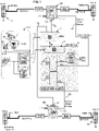
- Figure 1 shows a diagrammatical circuit layout of an electro-pneumatic braking system for a truck.
- the proposed configuration is also valid for any kind of heavy-duty vehicles including buses and coaches.
- the truck considered here can be the traction unit in a tractor/trailer configuration or a utility 'carrier' truck.
- the electro-pneumatic brake system comprises a service brake arrangement and a park brake arrangement.
- the service brake arrangement is configured to operate either under a normal brake operating mode NF or under a redundant operating mode BF in case the normal brake operating mode becomes unavailable for any reason.
- brake actuators 14 There may be provided more than 4 brake actuators 14, in case there are two front axles, and/or two or more rear axles.
- the number of brake actuators can amount to 2,4,6,8, or more. It is worth noting that some brake actuators can be deprived of the parking brake function.
- the number of brake actuators can be twice the number of axles.
- trailer brake actuators can be similar to truck brake actuators.
- each axle or group of axles is equipped with a brake module, e.g. in the illustrated example a front axle brake module FBM (also denoted 9F) and one (or more) rear axle brake module RBM (also denoted 9R).
- a brake module e.g. in the illustrated example a front axle brake module FBM (also denoted 9F) and one (or more) rear axle brake module RBM (also denoted 9R).
- the front axle brake module FBM provides pneumatic brake pressure to the left and right front pneumatic brake actuators (FW-L, FW-R).
- the rear axle brake module RBM provides pneumatic brake pressure to the left and right rear pneumatic brake actuators (RW-L, RW-R).
- Each of the front and rear axle brake modules (FBM, RBM) is an electro-pneumatic device providing a pneumatic relay function. In short, as illustrated at Fig 7 and Fig 8 , it selectively takes air from the compressed air supply ACx and selectively releases air to the atmosphere while following faithfully the control signals (electrical and/or pneumatic); its output is connected to the service brake chamber of the corresponding brake actuator (through a PCV valve or directly).
- Each of front and rear axle brake module (FBM, RBM) is controlled either via an electrical control input E1 or via a pneumatic control input E2 as will be explained below.
- anti-lock valves PCV Downstream the front and rear brake modules, there are provided anti-lock valves PCV which will be discussed more in details later.
- anti-lock valves can also be integrated in the rear axle brake modules (FBM, RBM).
- the front and rear brake modules are electrically controlled from a central braking control unit 'EBS' denoted 7.
- This control unit 7 calculates braking setpoints and outputs electrical control signals reflecting the braking setpoints respectively to the front brake module and the rear brake module.
- the timing strategy can differ between front and rear axles. Braking intensity and timing are worked out timely by the central braking control unit 7.
- the brake system comprises a service brake electric input device 16 (formed generally as a brake foot pedal) delivering a first input electric signal S16. It should be appreciated that the brake foot pedal is optional in the perspective of the present invention which can be applied to fully autonomous vehicles. Further the brake system comprises a park brake control device 18 (formed generally as handle, or the push-pull button 19 in the US version).
- VMM function block 100 designates high level control and medium level control of the vehicle trajectory.
- VMM Vehicle Motion Management.
- VMM function block 100 comprises one or more control units (71,72) adapted to process various inputs, in particular a first input electric signal S16 delivered by the foot brake pedal 16 but also the park brake control signal S18 delivered by a park brake actuator 18 (19 denoting the US variant).
- VMM function block 100 delivers various electrical control signals 76 to the central braking control unit 7.
- the central braking control unit 7 delivers one or more electrical control signals (74,75) to the front and rear axle brake modules FBM,RBM.
- electrical control signals delivered by VMM function block 100 which can be messages denoted 76, are sent to the central braking control unit 7. Further, electrical control signals delivered by VMM function block 100 which can be messages denoted 77, are sent to another control unit denoted 8 that will be discussed later.
- Autonomous drive control units 71,72 act as redundant units which work either in a parallel mode or in a master/slave mode.
- First and second autonomous drive control units 71,72 rely on one or more cameras 17 which provides a flow of images which are analyzed in autonomous drive control units 71,72.
- VMM function block 100 exhibits means for having accurate and real-time environmental awareness. This situation awareness allows VMM function block 100 to take decisions about steering and braking.
- Each of the front and rear axle brake modules (FBM,RBM) is controlled by the above mentioned electrical control signals (74,75) under a normal mode called "normal brake operating mode" NF, although there is provided a redundant way to control service brake that is discussed below.
- backup brake operating mode BF Whenever the normal mode is not fully operative, in particular from an electrical problem, disruption/lack of electrical supply at the central electronic brake control unit 7, from the viewpoint of at least one of to the front and rear axle brake modules FBM,RBM, there is provided in the system an alternative mode called backup brake operating mode BF.
- each of the front and rear axle brake modules can be controlled by a pneumatic backup brake control line 63,64 under the backup brake operating mode.
- the electro-valve denoted 92 (see later) is in opened state instead of closed state in the normal operating mode.
- first service brake backup line 8F for controlling at least the pneumatic control input of the front axle brake module (FBM, 9F) and a second service brake backup line 8R for controlling the pneumatic control input of the rear axle brake module (RBM, 9R).
- the first service brake backup line 8F and the second service brake backup line 8R are pneumatic lines.
- the first service brake backup line 8F is coupled to the output line 63 controlled independently from the central service brake unit 7.
- the second service brake backup line 8R is coupled to the output line 64 controlled independently from the central service brake unit 7.
- a compressor As known per se, there is provided a compressor, a first air reservoir coupled to the first air supply circuit AC1 and a second air reservoir coupled to the second air supply circuit AC2.
- the two air reservoirs are independent from one another.
- the first and second air supply circuits (AC1, AC2), are independent from one another.
- First and second air supply circuits have a service pressure set around 12 bars.
- first and second air supply circuits AC1, AC2 may have a service pressure comprised in the range [5 bars - 15 bars], preferably comprised in the range [7 bars - 12 bars].
- the first air supply circuit AC1 provides air under pressure to the rear axle brake module RBM.
- the second air supply circuit AC2 provides air under pressure to the front axle brake module FBM.
- AC1 is sometimes called 'primary' circuit
- AC2 is sometimes called 'secondary' circuit, since rear brakes are usually more powerful than front brakes.
- the air supply circuits are genetically denoted ACx in the present application.
- ACx is represented, irrespective of the value of x.
- the compressed air distribution from the various reservoirs may be any possible configurations and circuit layouts with more or less redundancy levels.
- the electro-pneumatic brake system comprises a first bistable relay valve 1 configured to supply parking brake pressure to the park brake chambers of the brake actuator(s) 14.
- the first bistable relay valve 1 is controlled through an input port 11.
- the output of the first bistable relay valve are denoted PBR1 and PBR2, and are pneumatically coupled to the park brake chambers of the brake actuators ( Figs 1 ,6)
- the electro-pneumatic brake system may comprise a second bistable relay valve 2 configured to supply trailer air pressure to the trailer.
- the second bistable relay valve 2 is controlled through an input port 12.
- the output of the second bistable relay valve is denoted 68, and is pneumatically coupled to the trailer control module (TCM, 13) cf Figs 1 to 5 .
- first bistable relay valve 1 is independent from the second bistable relay valve 2.
- Each of the relay valves 1,2 exhibits a back end loop circuit 21, 22 provided with a restriction 28. Stated otherwise, for each relay valve, the output of the relay valve is looped back to the respective input 11,12. This ensures stability of the pneumatic control and discards some inadvertent transients. In the present context, the above feature provides bistability to the relay valves. Thereby, only a 'positive' control (via P1 or P2) of the relay valve input can lead to a change of state of the relay valve.
- the system comprises a first pressure control device 4 for generating a first pressure denoted P1.
- the system comprises a second pressure control device 5 for generating a second pressure denoted P2.
- P1 and P2 Use of P1 and P2 will be discussed later.
- the first pressure control device 4 comprises an input valve 44 and an output valve 45 and a pressure sensor S1 for establishing/setting the first pressure P1.
- Pressure P1 is established according to electronically defined real-time pressure setpoint. A closed loop real-time control is achieved.
- Each of the input valve 44 and output valve 45 are normally closed ON/OFF valves. Energizing input valve 44 while maintaining output valve 45 at rest increases pressure P1, and conversely energizing output valve 45 while maintaining input valve 45 at rest decreases pressure P2.
- the first second control device 5 comprises an input valve 54 and an output valve 55 and a second pressure sensor S2 for establishing/setting the second pressure P2.
- Pressure P2 is established according to electronically defined real-time pressure setpoint. A closed loop real-time control is achieved. Energizing input valve 54 while maintaining output valve 55 at rest increases pressure P2, and conversely energizing output valve 55 while maintaining input valve 55 at rest decreases pressure P2.
- Each of the input valve 54 and output valve 55 are normally closed ON/OFF valves.
- system comprises a swap arrangement 3.
- the swap arrangement 3 configured to:
- the swap arrangement is spring loaded/biased to a rest state so that when non energized, i.e. in the rest state, the swap arrangement directs the first pressure P1 to the first Service Brake backup line 8F, and the valve arrangement directs the second pressure P2 to the second Service Brake backup line 8R.
- the swap arrangement comprises a first electro-valve 31.
- the swap arrangement comprises a second electro-valve 32, that may be controlled independently from the first electro-valve 31.
- the first electro-valve 31 and/or is a 4 ports - 2 positions type (4/2 valve, with four ports and two plunger positions), with an electric control.
- the second electro-valve 32 is a 4 ports - 2 positions type (4/2 valve, with four ports and two plunger positions), with an electric control.
- the input port of the first electro-valve 31 receives pressure P1 through line denoted 61.
- input 61 is directed to line 63 and line 65 blocked whereas, by contrast, when the electro-valve is energized (electrically activated) input 61 is directed to line 65 and line 63 is vented.
- the input port of the second electro-valve 32 receives pressure P2 through line denoted 62.
- input 62 is directed to line 64 and line 66 is blocked whereas, by contrast, when the electro-valve is energized (electrically activated) input 62 is directed to line 66 and line 64 is vented.
- the system may further comprise a pressure sensor S3 on the first service brake backup lines 8F.
- pressure sensor S4 is provided on the second Service Brake backup lines 8R.
- the pressure prevailing at S3 should be substantially equal to the pressure prevailing at S1 when the swap arrangement is at rest state. Conversely the pressure prevailing at S3 should be substantially null when the swap arrangement is energized since line 63 is vented.
- the pressure prevailing at S4 should be substantially equal to the pressure prevailing at S2 when the swap arrangement is at rest state. Conversely the pressure prevailing at S4 should be substantially null when the swap arrangement is energized since line 64 is vented.
- the system may further comprise pressure sensors (S5, S6) respectively on the output of the first relay valve first 1 and on the output of the second relay valve 2. These pressure sensors S5, S6 allow to check the state and proper operation of the relay valve.
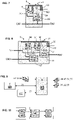
- the swap arrangement 3 may comprise a single combined 6/2 distributor denoted 34.
- this distributor can be a 6 ports - 2 positions type or a 7 ports - 2 positions type.
- This distributor is similar to a combination of electro-valves 31 32 of the first embodiment working simultaneously.
- the single combined 6/2 distributor is pneumatically controlled from an electro-valve named here third electro-valve 33.
- a movable plunger movable between 2 positions and biased to a rest position via spring-loaded arrangement.
- the pneumatic control line 69 connects the output of third electro-valve 33 to the plunger control of the distributor 34.
- the system comprises an air production module 6.
- the air production module is formed as a protective box.
- the air production module houses at least the following components :
- the air production module houses an air production module control unit 8 (APM ECU in short).
- the APM ECU controls the first pressure control device 4 and the second pressure control device 5.
- the APM ECU 8 controls the input valve 44 and output valve 45 of the first pressure control device 4.
- the APM ECU 8 controls the input valve 54 and output valve 55 of the second pressure control device 5.
- the APM ECU 8 controls the first electro-valve 31. Also, the APM ECU 8 controls the second electro-valve 32.
- the APM ECU 8 controls the third electro-valve 33.
- the APM ECU 8 receives pressure values delivered by pressure sensors S1 to S6.
- the APM ECU 8 receives electrical control signals and/or data messages from VMM function block 100 (data flow 77). The APM ECU 8 exchanges data with central brake control unit 7 through data line denoted 78.
- the APM control unit 8 operates independently from the control unit 7 of the baseline service brake.
- the swap arrangement When no change is required on the parking brake, the swap arrangement connect/couple the first pressure P1 to the first service brake backup line 8F, illustrated in figure 2 and figure 4 .
- the swap arrangement connect/couple the second pressure P2 to the second service brake backup line 8R. Under this condition the redundant operating mode is ready, P1 and P2 follow the setpoints of the electrical control signals.
- the swap arrangement When a change is required on the parking brake, the swap arrangement connect/couple the first pressure P1 to the input of the first bistable relay valve 1 until a desired change of state is achieved. For example, when the parking brake need to be applied, the swap arrangement is activated and the first pressure P1 is set to 0 thereby purging the parking brake chamber through the park brake relay valve 1. When the parking brakes need to be released, the swap arrangement is activated and the first pressure P1 is set to service pressure thereby pressurizing the parking brake chambers through the park brake relay valve 1.
- the swap arrangement When a change is required on the trailer air supply, the swap arrangement connect/couple the first pressure P2 to the input of the second bistable relay valve 2 until a desired change of state is achieved.
- the swap arrangement when the trailer needs to be supplied, the swap arrangement is activated and the second pressure P2 is set to service pressure thereby pressurizing the trailer supply line through the trailer brake relay valve 2.
- the swap arrangement is activated and the second pressure P2 is set to 0 thereby purging the trailer supply line through the trailer brake relay valve 2.
- steps a1 and a2 denote respectively the step of generating a control pressure P1 and P2. This control is carried out iteratively in real-time and also depending on the function required either redundant service brake or change of state of park brake or change of state of trailer supply.
- Step b0 denotes the default state swap arrangement where P1 and P2 are directed respectively to the front and rear service brake backup lines.
- Step b1 denotes a process to change or confirm state regarding the park brake relay valve 1.
- Step b2 denotes a process to change or confirm state regarding the trailer supply relay valve 1.
- first and second pressure control device are allocated the redundant service brake function, without need to be used for parking brake or trailer.
- time sharing is optimal regarding use of first and second pressure control devices 4,5.
- wheel speed sensors at least one per braked wheel. As known per se individual with speeds is processed by the control unit to determine whether there is a wheel that starts locking or at least with a decreasing speed.
- Each of the front and rear axle brake modules FBM,RBM can be either in one integrated unit or in 3 physical units, with the PCV (pressure control valve) separated from the pneumatic relay function, as illustrated.
- PCV pressure control valve
- PCV pressure control valve
- ABS function anti-locking function
- PCV has a first valve in a series arrangement that can block the passage or air down to the brake chamber, and a second valve that can take out air from the brake chamber circuit and release it to the atmosphere. These valves are controlled in accordance with the real time analysis of the speed of each wheel. These valves can be controlled by the central braking unit 7 and/or in a redundant manner by the APM ECU 8.
- the PCV valves are controlled by the central braking control unit 7, and the PCV valves are controlled in the service brake redundant/backup mode by the APM ECU 8. Consequently, whenever the redundant/backup mode takes over the normal mode, braking performances are maintained at the expected level, i.e. there is no downgrading of braking performance.
- Regulation can occur as soon as one of the monitored wheel exhibits a decreasing speed, compared to the other wheels.
- the PCV pressure control valve
- the FBM which performs mainly a relay function (electrical + pneumatic control for this relay function).
- the pressure control valves can be integrated in the FBM and RBM respectively. Of course, a mixed configuration is possible.
- Front and rear axle brake modules (FBM,RBM)
- the pneumatic control input E2 arrives in an isolation electro-valve 92.
- the local control unit controls the pressure control device 91 that controls the relay valve 93 in the normal operating mode.
- the local control unit receives setpoints at electrical control input E1.
- An internal pneumatic line 90 coming from the isolation valve and going to the relay valve is inactive as long as the isolation valve is closed.
- the isolation valve 92 becomes open and the internal pneumatic line 90 conveys pressure P1 (or P2 respectively) to the relay valve.
- a single pneumatic power output is directed to left and right wheel.
- relay valves 93, 97 are independently controlled and do not deliver necessarily the same pressure ouput.
- a dedicated pneumatic power output is directed to left wheel and a dedicated pneumatic power output is directed to the right wheel.
- Differentiated left / right braking can participate in one or more trajectory control functions.
- the invention also concerns a variant version without trailer function.
- the outputs of these relay valves are directed conventionally to the park brake chambers and respectively where applicable the trailer control module.
- trailer control module 13 When trailer function is present, there is provided a trailer control module 13, to which are coupled the glad-hands that forms the interface to the trailer.
- the proposed configuration is a suitable for European regulation, USA regulation, for Australia regulation. Only the trailer control module 13 may support variations according to regulations.
- the trailer control module 13 is controlled via line 630 which is a derivation of line 63,8F. Said otherwise the first Service Brake backup line 8F) also controls the trailer brake control module.
- Data lines 74, 75,76, 77, 78 may be embodied in any form.
- data lines 76, 77, 78 are supported by a CAN bus architecture.
- Data lines 74,75 can be supported by a private bus or a CAN bus.
- time required to change a relay valve state is less than 10 seconds, preferably less than 5 seconds, more preferably less than 3 seconds.
- the swap arrangement needs to be energized at least during this process, but not much more; thereby electrical consumption of the swap arrangement is very low.
- the consumption of the swap arrangement is null.
- the promoted configuration only needs to add the swap arrangement to a known configuration, thereby emphasizing the cost effectiveness of the promoted solution.
Landscapes
- Engineering & Computer Science (AREA)
- Mechanical Engineering (AREA)
- Transportation (AREA)
- General Engineering & Computer Science (AREA)
- Physics & Mathematics (AREA)
- Fluid Mechanics (AREA)
- Valves And Accessory Devices For Braking Systems (AREA)
- Braking Systems And Boosters (AREA)
- Regulating Braking Force (AREA)
Priority Applications (3)
| Application Number | Priority Date | Filing Date | Title |
|---|---|---|---|
| EP21183861.0A EP4116161B1 (de) | 2021-07-06 | 2021-07-06 | Redundantes bremssystem für schwerlastfahrzeuge |
| CN202210788971.1A CN115583227A (zh) | 2021-07-06 | 2022-07-06 | 重型车辆冗余制动系统 |
| US17/858,210 US12365323B2 (en) | 2021-07-06 | 2022-07-06 | Heavy duty vehicle redundant braking system |
Applications Claiming Priority (1)
| Application Number | Priority Date | Filing Date | Title |
|---|---|---|---|
| EP21183861.0A EP4116161B1 (de) | 2021-07-06 | 2021-07-06 | Redundantes bremssystem für schwerlastfahrzeuge |
Publications (3)
| Publication Number | Publication Date |
|---|---|
| EP4116161A1 true EP4116161A1 (de) | 2023-01-11 |
| EP4116161B1 EP4116161B1 (de) | 2024-03-06 |
| EP4116161C0 EP4116161C0 (de) | 2024-03-06 |
Family
ID=76807535
Family Applications (1)
| Application Number | Title | Priority Date | Filing Date |
|---|---|---|---|
| EP21183861.0A Active EP4116161B1 (de) | 2021-07-06 | 2021-07-06 | Redundantes bremssystem für schwerlastfahrzeuge |
Country Status (3)
| Country | Link |
|---|---|
| US (1) | US12365323B2 (de) |
| EP (1) | EP4116161B1 (de) |
| CN (1) | CN115583227A (de) |
Cited By (5)
| Publication number | Priority date | Publication date | Assignee | Title |
|---|---|---|---|---|
| EP4707090A1 (de) | 2024-09-10 | 2026-03-11 | KB Intellectual Property GmbH & Co. KG | Redundantes bremssystem gesteuert durch ein achsmodul |
| EP4707091A1 (de) | 2024-09-10 | 2026-03-11 | KB Intellectual Property GmbH & Co. KG | Redundantes bremssystem |
| EP4707086A1 (de) | 2024-09-10 | 2026-03-11 | KB Intellectual Property GmbH & Co. KG | Redundantes bremssystem gesteuert durch einen zentralen druckmodulator |
| EP4711219A1 (de) | 2024-09-12 | 2026-03-18 | KB Intellectual Property GmbH & Co. KG | Redundante bremsaktuatorsteuerung und versorgungsschnittstelle mit einem eingangsspannungspegel |
| EP4711221A1 (de) | 2024-09-12 | 2026-03-18 | KB Intellectual Property GmbH & Co. KG | Redundante bremsaktuatorsteuerung und versorgungsschnittstelle mit verschiedenen eingangsspannungsniveaus |
Families Citing this family (2)
| Publication number | Priority date | Publication date | Assignee | Title |
|---|---|---|---|---|
| EP4001031B1 (de) * | 2020-11-13 | 2024-01-03 | Volvo Truck Corporation | Elektropneumatisches bremssystem für ein fahrzeug mit einem feststellbremssystem als reserveverzögerungssystem |
| US20250128681A1 (en) * | 2023-10-18 | 2025-04-24 | Ford Global Technologies, Llc | Brake architecture for combined hydraulic and electromechanical braking system |
Citations (4)
| Publication number | Priority date | Publication date | Assignee | Title |
|---|---|---|---|---|
| EP3564082A1 (de) | 2018-05-03 | 2019-11-06 | Volvo Truck Corporation | Redundantes bremssystem für schwerlastfahrzeuge |
| US20200047730A1 (en) * | 2017-03-21 | 2020-02-13 | Wabco Gmbh | Integrated trailer control module with external electro-pneumatic parking brake unit |
| US20210078556A1 (en) * | 2018-05-03 | 2021-03-18 | Volvo Truck Corporation | Redundant motion control for a vehicle with a redundant braking arrangement |
| US20210122350A1 (en) * | 2018-05-03 | 2021-04-29 | Volvo Truck Corporation | Heavy duty vehicle redundant braking system |
Family Cites Families (3)
| Publication number | Priority date | Publication date | Assignee | Title |
|---|---|---|---|---|
| AT338125B (de) * | 1972-11-02 | 1977-07-25 | Bosch Gmbh Robert | Pneumatische zweileitungs-mehrkreis-bremsanlage fur kraftfahrzeug-zuge |
| DE102005058799A1 (de) * | 2005-12-09 | 2007-06-14 | Wabco Gmbh | Elektropneumatische Bremssteuerungseinrichtung |
| EP3415386B1 (de) * | 2017-06-16 | 2019-12-11 | KNORR-BREMSE Systeme für Nutzfahrzeuge GmbH | Fahrzeugbremssystem |
-
2021
- 2021-07-06 EP EP21183861.0A patent/EP4116161B1/de active Active
-
2022
- 2022-07-06 US US17/858,210 patent/US12365323B2/en active Active
- 2022-07-06 CN CN202210788971.1A patent/CN115583227A/zh active Pending
Patent Citations (5)
| Publication number | Priority date | Publication date | Assignee | Title |
|---|---|---|---|---|
| US20200047730A1 (en) * | 2017-03-21 | 2020-02-13 | Wabco Gmbh | Integrated trailer control module with external electro-pneumatic parking brake unit |
| EP3564082A1 (de) | 2018-05-03 | 2019-11-06 | Volvo Truck Corporation | Redundantes bremssystem für schwerlastfahrzeuge |
| US20190337502A1 (en) * | 2018-05-03 | 2019-11-07 | Volvo Truck Corporation | Heavy duty vehicle redundant braking system |
| US20210078556A1 (en) * | 2018-05-03 | 2021-03-18 | Volvo Truck Corporation | Redundant motion control for a vehicle with a redundant braking arrangement |
| US20210122350A1 (en) * | 2018-05-03 | 2021-04-29 | Volvo Truck Corporation | Heavy duty vehicle redundant braking system |
Cited By (7)
| Publication number | Priority date | Publication date | Assignee | Title |
|---|---|---|---|---|
| EP4707090A1 (de) | 2024-09-10 | 2026-03-11 | KB Intellectual Property GmbH & Co. KG | Redundantes bremssystem gesteuert durch ein achsmodul |
| EP4707091A1 (de) | 2024-09-10 | 2026-03-11 | KB Intellectual Property GmbH & Co. KG | Redundantes bremssystem |
| EP4707086A1 (de) | 2024-09-10 | 2026-03-11 | KB Intellectual Property GmbH & Co. KG | Redundantes bremssystem gesteuert durch einen zentralen druckmodulator |
| EP4711219A1 (de) | 2024-09-12 | 2026-03-18 | KB Intellectual Property GmbH & Co. KG | Redundante bremsaktuatorsteuerung und versorgungsschnittstelle mit einem eingangsspannungspegel |
| EP4711221A1 (de) | 2024-09-12 | 2026-03-18 | KB Intellectual Property GmbH & Co. KG | Redundante bremsaktuatorsteuerung und versorgungsschnittstelle mit verschiedenen eingangsspannungsniveaus |
| WO2026057222A1 (en) | 2024-09-12 | 2026-03-19 | Kb Intellectual Property Gmbh & Co. Kg | Redundant brake actuator control and supply interface using different input voltage levels |
| WO2026057231A1 (en) | 2024-09-12 | 2026-03-19 | Kb Intellectual Property Gmbh & Co. Kg | Redundant brake actuator control and supply interface using one input voltage level |
Also Published As
| Publication number | Publication date |
|---|---|
| CN115583227A (zh) | 2023-01-10 |
| EP4116161B1 (de) | 2024-03-06 |
| US20230009033A1 (en) | 2023-01-12 |
| EP4116161C0 (de) | 2024-03-06 |
| US12365323B2 (en) | 2025-07-22 |
Similar Documents
| Publication | Publication Date | Title |
|---|---|---|
| EP4116161B1 (de) | Redundantes bremssystem für schwerlastfahrzeuge | |
| US11180127B2 (en) | Heavy duty vehicle redundant braking system | |
| CN113518738B (zh) | 用于商用车的电动气动制动系统 | |
| CN108883755B (zh) | 商用车辆中的能电子控制的气动制动系统和用于电子控制气动制动系统的方法 | |
| US11702054B2 (en) | Redundant braking unit for a braking system and system using same | |
| CN114616146A (zh) | 具有安全急停功能的制动系统和对此的方法 | |
| US20210122350A1 (en) | Heavy duty vehicle redundant braking system | |
| US20070194622A1 (en) | Brake control apparatus | |
| KR20210003905A (ko) | 중복 제동 장치를 가진 차량을 위한 중복 모션 제어 | |
| CN102991493A (zh) | 用于挂车制动器的阀组件 | |
| CN110785330A (zh) | 车辆制动系统 | |
| RU2730741C1 (ru) | Блок подготовки воздуха для тормозного устройства транспортного средства хозяйственного назначения, тормозное устройство и способ эксплуатации блока подготовки воздуха | |
| CN113365889A (zh) | 具有针对单独车轮的abs控制部的驻车制动器设施 | |
| CN114728644B (zh) | 用于机动车辆的制动系统以及拖车控制模块 | |
| US20070152500A1 (en) | Brake control apparatus and method for controlling the brake | |
| US12240426B2 (en) | Electropneumatic device with a protective valve unit | |
| JP2548747B2 (ja) | 液圧ブレーキ装置 | |
| JP2020006952A (ja) | ブレーキシステム | |
| US20260070536A1 (en) | Redundant Brake System | |
| JPH11124018A (ja) | 坂道発進補助装置を備えたブレーキ制御システム | |
| US20250187575A1 (en) | Brake system of a vehicle with redundant parking brake function | |
| JP2889720B2 (ja) | 後2軸車用ブレーキシステム | |
| JPH0958442A (ja) | トラクタ・トレーラ連結車におけるトラクタ側エアブレーキシステム | |
| GB2621839A (en) | Trailer brake control system | |
| CN121893925A (zh) | 挂车控制阀及控制挂车制动压力的方法 |
Legal Events
| Date | Code | Title | Description |
|---|---|---|---|
| PUAI | Public reference made under article 153(3) epc to a published international application that has entered the european phase |
Free format text: ORIGINAL CODE: 0009012 |
|
| STAA | Information on the status of an ep patent application or granted ep patent |
Free format text: STATUS: THE APPLICATION HAS BEEN PUBLISHED |
|
| AK | Designated contracting states |
Kind code of ref document: A1 Designated state(s): AL AT BE BG CH CY CZ DE DK EE ES FI FR GB GR HR HU IE IS IT LI LT LU LV MC MK MT NL NO PL PT RO RS SE SI SK SM TR |
|
| STAA | Information on the status of an ep patent application or granted ep patent |
Free format text: STATUS: REQUEST FOR EXAMINATION WAS MADE |
|
| 17P | Request for examination filed |
Effective date: 20230706 |
|
| RBV | Designated contracting states (corrected) |
Designated state(s): AL AT BE BG CH CY CZ DE DK EE ES FI FR GB GR HR HU IE IS IT LI LT LU LV MC MK MT NL NO PL PT RO RS SE SI SK SM TR |
|
| RIC1 | Information provided on ipc code assigned before grant |
Ipc: B60T 13/68 20060101AFI20230818BHEP |
|
| GRAP | Despatch of communication of intention to grant a patent |
Free format text: ORIGINAL CODE: EPIDOSNIGR1 |
|
| STAA | Information on the status of an ep patent application or granted ep patent |
Free format text: STATUS: GRANT OF PATENT IS INTENDED |
|
| INTG | Intention to grant announced |
Effective date: 20230929 |
|
| GRAS | Grant fee paid |
Free format text: ORIGINAL CODE: EPIDOSNIGR3 |
|
| GRAA | (expected) grant |
Free format text: ORIGINAL CODE: 0009210 |
|
| STAA | Information on the status of an ep patent application or granted ep patent |
Free format text: STATUS: THE PATENT HAS BEEN GRANTED |
|
| RIN1 | Information on inventor provided before grant (corrected) |
Inventor name: FARRES, LIONEL Inventor name: MONNIER, MARTIN |
|
| AK | Designated contracting states |
Kind code of ref document: B1 Designated state(s): AL AT BE BG CH CY CZ DE DK EE ES FI FR GB GR HR HU IE IS IT LI LT LU LV MC MK MT NL NO PL PT RO RS SE SI SK SM TR |
|
| REG | Reference to a national code |
Ref country code: CH Ref legal event code: EP |
|
| REG | Reference to a national code |
Ref country code: DE Ref legal event code: R096 Ref document number: 602021010015 Country of ref document: DE |
|
| REG | Reference to a national code |
Ref country code: IE Ref legal event code: FG4D |
|
| U01 | Request for unitary effect filed |
Effective date: 20240405 |
|
| U07 | Unitary effect registered |
Designated state(s): AT BE BG DE DK EE FI FR IT LT LU LV MT NL PT SE SI Effective date: 20240415 |
|
| PG25 | Lapsed in a contracting state [announced via postgrant information from national office to epo] |
Ref country code: GR Free format text: LAPSE BECAUSE OF FAILURE TO SUBMIT A TRANSLATION OF THE DESCRIPTION OR TO PAY THE FEE WITHIN THE PRESCRIBED TIME-LIMIT Effective date: 20240607 |
|
| PG25 | Lapsed in a contracting state [announced via postgrant information from national office to epo] |
Ref country code: HR Free format text: LAPSE BECAUSE OF FAILURE TO SUBMIT A TRANSLATION OF THE DESCRIPTION OR TO PAY THE FEE WITHIN THE PRESCRIBED TIME-LIMIT Effective date: 20240306 Ref country code: RS Free format text: LAPSE BECAUSE OF FAILURE TO SUBMIT A TRANSLATION OF THE DESCRIPTION OR TO PAY THE FEE WITHIN THE PRESCRIBED TIME-LIMIT Effective date: 20240606 |
|
| PG25 | Lapsed in a contracting state [announced via postgrant information from national office to epo] |
Ref country code: ES Free format text: LAPSE BECAUSE OF FAILURE TO SUBMIT A TRANSLATION OF THE DESCRIPTION OR TO PAY THE FEE WITHIN THE PRESCRIBED TIME-LIMIT Effective date: 20240306 |
|
| PG25 | Lapsed in a contracting state [announced via postgrant information from national office to epo] |
Ref country code: RS Free format text: LAPSE BECAUSE OF FAILURE TO SUBMIT A TRANSLATION OF THE DESCRIPTION OR TO PAY THE FEE WITHIN THE PRESCRIBED TIME-LIMIT Effective date: 20240606 Ref country code: NO Free format text: LAPSE BECAUSE OF FAILURE TO SUBMIT A TRANSLATION OF THE DESCRIPTION OR TO PAY THE FEE WITHIN THE PRESCRIBED TIME-LIMIT Effective date: 20240606 Ref country code: HR Free format text: LAPSE BECAUSE OF FAILURE TO SUBMIT A TRANSLATION OF THE DESCRIPTION OR TO PAY THE FEE WITHIN THE PRESCRIBED TIME-LIMIT Effective date: 20240306 Ref country code: GR Free format text: LAPSE BECAUSE OF FAILURE TO SUBMIT A TRANSLATION OF THE DESCRIPTION OR TO PAY THE FEE WITHIN THE PRESCRIBED TIME-LIMIT Effective date: 20240607 Ref country code: ES Free format text: LAPSE BECAUSE OF FAILURE TO SUBMIT A TRANSLATION OF THE DESCRIPTION OR TO PAY THE FEE WITHIN THE PRESCRIBED TIME-LIMIT Effective date: 20240306 |
|
| U20 | Renewal fee for the european patent with unitary effect paid |
Year of fee payment: 4 Effective date: 20240725 |
|
| PG25 | Lapsed in a contracting state [announced via postgrant information from national office to epo] |
Ref country code: IS Free format text: LAPSE BECAUSE OF FAILURE TO SUBMIT A TRANSLATION OF THE DESCRIPTION OR TO PAY THE FEE WITHIN THE PRESCRIBED TIME-LIMIT Effective date: 20240706 |
|
| PG25 | Lapsed in a contracting state [announced via postgrant information from national office to epo] |
Ref country code: SM Free format text: LAPSE BECAUSE OF FAILURE TO SUBMIT A TRANSLATION OF THE DESCRIPTION OR TO PAY THE FEE WITHIN THE PRESCRIBED TIME-LIMIT Effective date: 20240306 |
|
| PG25 | Lapsed in a contracting state [announced via postgrant information from national office to epo] |
Ref country code: CZ Free format text: LAPSE BECAUSE OF FAILURE TO SUBMIT A TRANSLATION OF THE DESCRIPTION OR TO PAY THE FEE WITHIN THE PRESCRIBED TIME-LIMIT Effective date: 20240306 |
|
| PG25 | Lapsed in a contracting state [announced via postgrant information from national office to epo] |
Ref country code: PL Free format text: LAPSE BECAUSE OF FAILURE TO SUBMIT A TRANSLATION OF THE DESCRIPTION OR TO PAY THE FEE WITHIN THE PRESCRIBED TIME-LIMIT Effective date: 20240306 |
|
| PG25 | Lapsed in a contracting state [announced via postgrant information from national office to epo] |
Ref country code: SK Free format text: LAPSE BECAUSE OF FAILURE TO SUBMIT A TRANSLATION OF THE DESCRIPTION OR TO PAY THE FEE WITHIN THE PRESCRIBED TIME-LIMIT Effective date: 20240306 |
|
| PG25 | Lapsed in a contracting state [announced via postgrant information from national office to epo] |
Ref country code: SM Free format text: LAPSE BECAUSE OF FAILURE TO SUBMIT A TRANSLATION OF THE DESCRIPTION OR TO PAY THE FEE WITHIN THE PRESCRIBED TIME-LIMIT Effective date: 20240306 Ref country code: SK Free format text: LAPSE BECAUSE OF FAILURE TO SUBMIT A TRANSLATION OF THE DESCRIPTION OR TO PAY THE FEE WITHIN THE PRESCRIBED TIME-LIMIT Effective date: 20240306 Ref country code: RO Free format text: LAPSE BECAUSE OF FAILURE TO SUBMIT A TRANSLATION OF THE DESCRIPTION OR TO PAY THE FEE WITHIN THE PRESCRIBED TIME-LIMIT Effective date: 20240306 Ref country code: PL Free format text: LAPSE BECAUSE OF FAILURE TO SUBMIT A TRANSLATION OF THE DESCRIPTION OR TO PAY THE FEE WITHIN THE PRESCRIBED TIME-LIMIT Effective date: 20240306 Ref country code: IS Free format text: LAPSE BECAUSE OF FAILURE TO SUBMIT A TRANSLATION OF THE DESCRIPTION OR TO PAY THE FEE WITHIN THE PRESCRIBED TIME-LIMIT Effective date: 20240706 Ref country code: CZ Free format text: LAPSE BECAUSE OF FAILURE TO SUBMIT A TRANSLATION OF THE DESCRIPTION OR TO PAY THE FEE WITHIN THE PRESCRIBED TIME-LIMIT Effective date: 20240306 |
|
| REG | Reference to a national code |
Ref country code: DE Ref legal event code: R097 Ref document number: 602021010015 Country of ref document: DE |
|
| PLBE | No opposition filed within time limit |
Free format text: ORIGINAL CODE: 0009261 |
|
| STAA | Information on the status of an ep patent application or granted ep patent |
Free format text: STATUS: NO OPPOSITION FILED WITHIN TIME LIMIT |
|
| PG25 | Lapsed in a contracting state [announced via postgrant information from national office to epo] |
Ref country code: MC Free format text: LAPSE BECAUSE OF FAILURE TO SUBMIT A TRANSLATION OF THE DESCRIPTION OR TO PAY THE FEE WITHIN THE PRESCRIBED TIME-LIMIT Effective date: 20240306 |
|
| 26N | No opposition filed |
Effective date: 20241209 |
|
| REG | Reference to a national code |
Ref country code: CH Ref legal event code: PL |
|
| PG25 | Lapsed in a contracting state [announced via postgrant information from national office to epo] |
Ref country code: CH Free format text: LAPSE BECAUSE OF NON-PAYMENT OF DUE FEES Effective date: 20240731 |
|
| PG25 | Lapsed in a contracting state [announced via postgrant information from national office to epo] |
Ref country code: IE Free format text: LAPSE BECAUSE OF NON-PAYMENT OF DUE FEES Effective date: 20240706 |
|
| PG25 | Lapsed in a contracting state [announced via postgrant information from national office to epo] |
Ref country code: CY Free format text: LAPSE BECAUSE OF FAILURE TO SUBMIT A TRANSLATION OF THE DESCRIPTION OR TO PAY THE FEE WITHIN THE PRESCRIBED TIME-LIMIT; INVALID AB INITIO Effective date: 20210706 |
|
| PG25 | Lapsed in a contracting state [announced via postgrant information from national office to epo] |
Ref country code: HU Free format text: LAPSE BECAUSE OF FAILURE TO SUBMIT A TRANSLATION OF THE DESCRIPTION OR TO PAY THE FEE WITHIN THE PRESCRIBED TIME-LIMIT; INVALID AB INITIO Effective date: 20210706 |
|
| GBPC | Gb: european patent ceased through non-payment of renewal fee |
Effective date: 20250706 |
|
| U90 | Renewal fees not paid: noting of loss of rights |
Free format text: RENEWAL FEE NOT PAID FOR YEAR 05 Effective date: 20260223 |
|
| PG25 | Lapsed in a contracting state [announced via postgrant information from national office to epo] |
Ref country code: GB Free format text: LAPSE BECAUSE OF NON-PAYMENT OF DUE FEES Effective date: 20250706 |