EP4116251B9 - Steuerungsverfahren eines krans zum auswählen und anwenden einer bevorzugten lastkurve in abhängigkeit von der neigung eines auslegerstrukturelements - Google Patents
Steuerungsverfahren eines krans zum auswählen und anwenden einer bevorzugten lastkurve in abhängigkeit von der neigung eines auslegerstrukturelements Download PDFInfo
- Publication number
- EP4116251B9 EP4116251B9 EP22180514.6A EP22180514A EP4116251B9 EP 4116251 B9 EP4116251 B9 EP 4116251B9 EP 22180514 A EP22180514 A EP 22180514A EP 4116251 B9 EP4116251 B9 EP 4116251B9
- Authority
- EP
- European Patent Office
- Prior art keywords
- jib
- structural element
- crane
- load curve
- actual
- Prior art date
- Legal status (The legal status is an assumption and is not a legal conclusion. Google has not performed a legal analysis and makes no representation as to the accuracy of the status listed.)
- Active
Links
Images

Classifications
-
- B—PERFORMING OPERATIONS; TRANSPORTING
- B66—HOISTING; LIFTING; HAULING
- B66C—CRANES; LOAD-ENGAGING ELEMENTS OR DEVICES FOR CRANES, CAPSTANS, WINCHES, OR TACKLES
- B66C13/00—Other constructional features or details
- B66C13/16—Applications of indicating, registering, or weighing devices
-
- B—PERFORMING OPERATIONS; TRANSPORTING
- B66—HOISTING; LIFTING; HAULING
- B66C—CRANES; LOAD-ENGAGING ELEMENTS OR DEVICES FOR CRANES, CAPSTANS, WINCHES, OR TACKLES
- B66C23/00—Cranes comprising essentially a beam, boom, or triangular structure acting as a cantilever and mounted for translatory of swinging movements in vertical or horizontal planes or a combination of such movements, e.g. jib-cranes, derricks, tower cranes
- B66C23/18—Cranes comprising essentially a beam, boom, or triangular structure acting as a cantilever and mounted for translatory of swinging movements in vertical or horizontal planes or a combination of such movements, e.g. jib-cranes, derricks, tower cranes specially adapted for use in particular purposes
- B66C23/26—Cranes comprising essentially a beam, boom, or triangular structure acting as a cantilever and mounted for translatory of swinging movements in vertical or horizontal planes or a combination of such movements, e.g. jib-cranes, derricks, tower cranes specially adapted for use in particular purposes for use on building sites; constructed, e.g. with separable parts, to facilitate rapid assembly or dismantling, for operation at successively higher levels, for transport by road or rail
- B66C23/34—Self-erecting cranes, i.e. with hoisting gear adapted for crane erection purposes
- B66C23/342—Self-erecting cranes, i.e. with hoisting gear adapted for crane erection purposes with telescopic elements
-
- B—PERFORMING OPERATIONS; TRANSPORTING
- B66—HOISTING; LIFTING; HAULING
- B66C—CRANES; LOAD-ENGAGING ELEMENTS OR DEVICES FOR CRANES, CAPSTANS, WINCHES, OR TACKLES
- B66C13/00—Other constructional features or details
- B66C13/18—Control systems or devices
- B66C13/22—Control systems or devices for electric drives
-
- B—PERFORMING OPERATIONS; TRANSPORTING
- B66—HOISTING; LIFTING; HAULING
- B66C—CRANES; LOAD-ENGAGING ELEMENTS OR DEVICES FOR CRANES, CAPSTANS, WINCHES, OR TACKLES
- B66C23/00—Cranes comprising essentially a beam, boom, or triangular structure acting as a cantilever and mounted for translatory of swinging movements in vertical or horizontal planes or a combination of such movements, e.g. jib-cranes, derricks, tower cranes
- B66C23/18—Cranes comprising essentially a beam, boom, or triangular structure acting as a cantilever and mounted for translatory of swinging movements in vertical or horizontal planes or a combination of such movements, e.g. jib-cranes, derricks, tower cranes specially adapted for use in particular purposes
- B66C23/26—Cranes comprising essentially a beam, boom, or triangular structure acting as a cantilever and mounted for translatory of swinging movements in vertical or horizontal planes or a combination of such movements, e.g. jib-cranes, derricks, tower cranes specially adapted for use in particular purposes for use on building sites; constructed, e.g. with separable parts, to facilitate rapid assembly or dismantling, for operation at successively higher levels, for transport by road or rail
- B66C23/34—Self-erecting cranes, i.e. with hoisting gear adapted for crane erection purposes
-
- B—PERFORMING OPERATIONS; TRANSPORTING
- B66—HOISTING; LIFTING; HAULING
- B66C—CRANES; LOAD-ENGAGING ELEMENTS OR DEVICES FOR CRANES, CAPSTANS, WINCHES, OR TACKLES
- B66C23/00—Cranes comprising essentially a beam, boom, or triangular structure acting as a cantilever and mounted for translatory of swinging movements in vertical or horizontal planes or a combination of such movements, e.g. jib-cranes, derricks, tower cranes
- B66C23/62—Constructional features or details
- B66C23/64—Jibs
- B66C23/68—Jibs foldable or otherwise adjustable in configuration
-
- B—PERFORMING OPERATIONS; TRANSPORTING
- B66—HOISTING; LIFTING; HAULING
- B66C—CRANES; LOAD-ENGAGING ELEMENTS OR DEVICES FOR CRANES, CAPSTANS, WINCHES, OR TACKLES
- B66C23/00—Cranes comprising essentially a beam, boom, or triangular structure acting as a cantilever and mounted for translatory of swinging movements in vertical or horizontal planes or a combination of such movements, e.g. jib-cranes, derricks, tower cranes
- B66C23/88—Safety gear
- B66C23/90—Devices for indicating or limiting lifting moment
- B66C23/905—Devices for indicating or limiting lifting moment electrical
Definitions
- the invention relates to a crane control method for selecting and applying a preferential load curve adapted to a working configuration of a crane. It also relates to a crane comprising a mast supporting a luffing jib and means for implementing such a crane control method.
- the invention finds a preferred, and non-limiting, application for an automated assembly crane with a luffing and folding jib.
- Such a crane comprises a mast, generally of the foldable mast or telescopic mast type, supporting a raisable and foldable boom comprising boom structural elements articulated together.
- a self-erecting crane is configurable between a transport configuration in which the mast and the boom are brought together or folded on themselves or side by side, and at least one working configuration in which the mast is vertical and the boom is unfolded to allow lifting and moving maneuvers of a load along the boom.
- an assembler selects a load curve adapted to the working configuration of the crane; it being noted that this load curve will depend on the working configuration of the crane, such as the length of the boom, the height of the boom, the inclination of the boom. Also, an error in the selection by the assembler of the load curve adapted to the actual working configuration of the crane can have serious consequences, such as damage or even collapse of the lifting and handling device.
- the present invention aims to resolve all or part of this drawback, by proposing a solution for knowing at least partially the actual working configuration of the crane, and automatically deducing the load curve adapted to this actual working configuration.
- the invention proposes to evaluate the working configuration of the crane from a measurement of the inclination of at least one structural element of the boom, thus making it possible to understand whether the boom is horizontal or raised, and therefore making it possible to adapt the load curve according to such an inclination.
- Such a solution is particularly advantageous because it bases the selection of the preferred load curve on the inclinations of two boom structural elements, thus allowing access to a greater number of crane working configurations, and in particular to working configurations in which the boom is partially extended.
- the two boom structural elements comprise a first boom structural element, forming a boom foot, which is hinged to the mast, and a second boom structural element hinged to the first boom structural element.
- the luffing boom includes a third boom structural member, forming a boom tip, which is hinged to the second boom structural member and is movable between two positions including a stowed position in which the third boom structural member is folded and folded toward the second boom structural member, and a deployed position in which the third boom structural member is unfolded and extends in alignment with the second boom structural member, wherein a position detection step implements a detection of the actual position of the third boom structural element among its two positions, and wherein the selection step implements the automated selection of the preferential load curve according to the actual inclinations of the two boom structural elements and the actual position of the third boom structural element, said preferential load curve being selected from the plurality of load curves calculated beforehand for several inclinations of the two boom structural elements and for the two positions of the third boom structural element.
- the selection of the preferred load curve is based on the inclinations of the first two structural elements of the boom, and also on the position of the third structural element forming the boom tip, which will allow access to an even greater number of working configurations of the crane, and in particular to working configurations in which the boom tip is deployed or retracted.
- the selection of the preferred load curve is also based on the actual height of the luffing jib (similar to the height under hook generally considered in the field of cranes), increasing the range of working configurations for the crane.
- the selection step is carried out by a control/command system, which control/command system is connected to the memory storing the plurality of load curves and to operating actuators of the crane to carry out the piloting step.
- the raisable boom is foldable and comprises at least two boom structural elements articulated together and on which respective inclinometers are mounted for measuring actual inclinations of the two boom structural elements relative to the reference axis in the working configuration
- the control/command system is configured to operate the automated selection of the preferential load curve as a function of the actual inclinations of said two boom structural elements, said preferential load curve being selected from the plurality of load curves calculated beforehand for several inclinations of said two boom structural elements.
- the crane comprises a height measuring device implementing a measurement of an actual height of the luffing boom relative to a ground in the working configuration
- the control/command system is configured to operate the automated selection of the preferred load curve as a function of the actual inclination of the boom structural element and the actual height of the luffing boom, said preferred load curve being selected from the plurality of load curves previously calculated for several inclinations of said boom structural element and for several heights of the luffing boom.
- the mast is a telescopic mast comprising mast structural members mounted in a telescoping manner
- the height measuring device comprises a sensor which measures a level of telescoping between the mast structural members.
- height measuring devices such as a laser rangefinder, an ultrasonic rangefinder, a camera, etc.
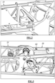
- a crane 1 comprises a mast 2 mounted on a platform 10 and supporting a luffing jib 3.
- the mast 2 may be a foldable mast comprising mast elements articulated together, or be a telescopic mast comprising mast structural elements 21, 22 mounted in a telescopic manner as in the example illustrated.
- the luffing jib 3 is a foldable jib comprising jib structural elements 31, 32, 33 articulated together.
- the first boom structural element 31 and the second boom structural element 32 form the first two boom structural elements 31, 32.
- the mast 2 is deployed, and more specifically the mast structural elements 21, 22 are unfolded (in the folding mast version) or are deployed (in the telescopic mast version).
- the crane 1 may be of the self-erecting crane type, and may thus also be configurable in a CT transport configuration (not shown) in which the mast 2 and the luffing jib 3 are brought together on themselves or side by side and extend horizontally, in order to form a transportable package, and more specifically in which the mast structural elements 21, 22 are folded on themselves (in the folding mast version) or are retracted on themselves (in the telescopic mast version) and the boom structural elements 31, 32, 33 are both folded on themselves and on the mast structural elements 21, 22.
- the crane 1 is thus equipped with a motorized folding/unfolding system 7 which is coupled to the mast 2 and to the luffing jib 3 to act on the mast 2 and the luffing jib 3 to fold and unfold the crane 1 and thus move it from a working configuration to the transport configuration, and vice versa.
- this motorized folding/unfolding system 7 makes it possible to carry out configuration change operations implementing kinematics for folding and unfolding the luffing jib 3, and where appropriate for deploying and retracting the mast 2.
- the crane 1 further comprises a control/command system 5 connected to maneuvering actuators (for example a lifting winch 81 for lowering/raising a lifting hook 9, and a distribution winch 82 for moving a distribution trolley 4 along the boom 3).
- This control/command system 5 is configured to control lifting and moving maneuvers of a load along the luffing boom 3 in the working configuration of the crane 1, by controlling the maneuvering actuators 81, 82, as a function of pilot commands exercised by a crane pilot on a pilot interface, and by applying a preferential load curve; such a preferential load curve defining maximum operating loads at the spans considered along the luffing boom 3.
- This control/command system 5 can for example be a microcontroller, a microprocessor, or an electronic control card.
- the crane 1 comprises at least one inclinometer mounted on one of the boom structural elements 32, 32, 33 for measuring inclinations actual values of this arrow element relative to a reference axis, such as a horizontal axis or a vertical axis.
- the crane 1 comprises two inclinometers, namely a first inclinometer 61 and a second inclinometer 62, mounted on the first boom structural element 31 and the second boom structural element 32 respectively, for measuring the actual inclinations of this first boom element 31 and this second boom element 32 respectively.
- the first inclinometer 61 fixed on the first boom structural element 31, can be placed near the articulation of the first boom element 31 on the top of the mast.
- the second inclinometer 62 fixed on the second boom structural element 32, can be placed near the joint between the second boom structural element 32 and the first boom structural element 31.
- Each of the two inclinometers 61, 62 may be an inclinometer with absolute angular measurement relative to the vertical or the horizontal, depending on the model.
- the inclinometers 61, 62 may be small-sized sensors which are directly mounted in a protected location in the structure of each boom structural element 31, 32.
- This detector 63 which detects the actual position of the third boom structural element 33 among its two positions (retracted position and deployed position).
- This detector 63 may be an inclinometer mounted on the third boom structural element 33, or alternatively a position or proximity sensor which is mounted on the second boom structural element 32 or on the third boom structural element 33 to detect the presence/absence of the third boom structural element 33 in one of the two positions.
- the control/command system 5 is connected to the two inclinometers 61, 62 and to a memory 50 storing a plurality of load curves calculated beforehand for several inclinations of the first two structural boom elements 31, 32.
- the control/command system 5 is configured to operate an automated selection of a preferential load curve as a function of the actual inclinations of the first two structural boom elements 31, 32, the preferential load curve being selected from the plurality of load curves stored in the memory 50.
- control/command system 5 is connected to the two inclinometers 61, 62 and also to the detector 63, and the memory 50 stores a plurality of load curves calculated beforehand for several inclinations of the first two boom structural elements 31, 32 and for the two positions of the third boom structural element 33.
- the control/command system 5 is configured to operate an automated selection of a preferential load curve as a function of the actual inclinations of the first two boom structural elements 31, 32 and the actual position of the third boom structural element 33, the preferential load curve being selected from the plurality of load curves stored in the memory 50.
- control/command system 5 selects the preferred load curve which is adapted to the working configuration of the crane 1; this working configuration being dependent on the actual inclinations of the first two structural boom elements 31, 32 and the actual position of the third structural boom element 33.
- the invention thus makes it possible to select and apply a preferred load curve adapted to the working configuration of the crane 1.
- this height sensor 64 may be a sensor that measures a level of telescoping between the mast structural elements 21, 22.
- the control/command system 5 is connected to the two inclinometers 61, 62, possibly to the detector 63, and to the height sensor 64, and the memory 50 stores a plurality of load curves calculated in advance for several inclinations of the first two boom structural elements 31, 32, for the two positions of the third boom structural element 33, and for several heights of the luffing jib 3.
- control/command system 5 is configured to operate an automated selection of a preferred load curve as a function of the actual inclinations of the first two boom structural elements 31, 32, the actual position of the third boom structural element 33 and the actual height of the luffing jib 3, the preferred load curve being selected from the plurality of load curves stored in the memory 50.
- control/command system 5 recovers measurement data from the different sensors 61, 62, 63, 64, and automatically applies the preferential load curve which is adapted to the working configuration deduced from this measurement data.
Landscapes
- Engineering & Computer Science (AREA)
- Mechanical Engineering (AREA)
- Structural Engineering (AREA)
- Transportation (AREA)
- Automation & Control Theory (AREA)
- Jib Cranes (AREA)
Claims (15)
- Verfahren zum Steuern eines Krans (1) zum Auswählen und Anwenden einer bevorzugten Lastkurve, die für eine Arbeitskonfiguration des Krans (1) geeignet ist, wobei der Kran (1) einen Mast (2) umfasst, der einen Verstellausleger (3) trägt, der mindestens ein Auslegerstrukturelement (31; 32) umfasst, wobei das Verfahren zum Steuern des Krans (1) die folgenden Schritte durchführt:- einen Schritt des Messens einer Neigung, der eine Messung einer tatsächlichen Neigung des Auslegerstrukturelements (31; 32) in Bezug auf eine Referenzachse in der Arbeitskonfiguration mittels eines an dem Auslegerstrukturelement montierten Neigungsmessers (61; 62) durchführt;- einen Auswahlschritt, der eine automatisierte Auswahl der bevorzugten Lastkurve in Abhängigkeit von der tatsächlichen Neigung des Auslegerstrukturelements (31; 32) durchführt, wobei die bevorzugte Lastkurve aus einer Vielzahl von in einem Speicher (50) gespeicherten und zuvor für mehrere Neigungen des Auslegerstrukturelements (31; 32) berechneten Lastkurven ausgewählt wird;- einen Steuerschritt, der eine Anwendung der bevorzugten Lastkurve für Hebe- und Bewegungsmanöver einer Last entlang des Verstellauslegers (3) in der Arbeitskonfiguration des Krans (1) durchführt.
- Steuerverfahren nach Anspruch 1, wobei der Verstellausleger (3) zusammenklappbar ist und mindestens zwei zueinander gelenkige Auslegerstrukturelemente (31, 32) umfasst, und wobei:- der Schritt des Messens der Neigung eine Messung der tatsächlichen Neigungen der beiden Auslegerstrukturelemente (31, 32) in Bezug auf die Referenzachse in der Arbeitskonfiguration mittels an den beiden Auslegerstrukturelementen (31, 32) montierten Neigungsmessern (61, 62) durchführt; und- der Auswahlschritt die automatisierte Auswahl der bevorzugten Lastkurve in Abhängigkeit von den tatsächlichen Neigungen der beiden Auslegerstrukturelemente (31, 32) durchführt, wobei die bevorzugte Lastkurve aus der Vielzahl von zuvor für mehrere Neigungen der beiden Auslegerstrukturelemente (31, 32) berechneten Lastkurven ausgewählt wird.
- Steuerverfahren nach Anspruch 2, wobei die beiden Auslegerstrukturelemente (31, 32) ein erstes Auslegerstrukturelement (31), das einen Auslegerfuß bildet, der gelenkig mit dem Mast (2) verbunden ist, und ein zweites Auslegerstrukturelement (32) umfassen, das gelenkig mit dem ersten Auslegerstrukturelement (31) verbunden ist.
- Steuerverfahren nach Anspruch 3, wobei der Verstellausleger (3) ein drittes Auslegerstrukturelement (33) umfasst, das eine Auslegerspitze bildet, das gelenkig mit dem zweiten Auslegerstrukturelement (32) verbunden ist und das zwischen zwei Positionen verschiebbar ist, die eine eingefahrene Position, in der das dritte Auslegerstrukturelement (33) zusammengeklappt und in Richtung des zweiten Auslegerstrukturelements (32) umgeklappt ist, und eine ausgefahrene Position umfassen, in der das dritte Auslegerstrukturelement (33) ausgeklappt ist und das zweite Auslegerstrukturelement (32) in gerader Linie verlängert,wobei ein Schritt des Detektierens einer Position eine Detektion der tatsächlichen Position des dritten Auslegerstrukturelements (33) zwischen seinen beiden Positionen durchführt,und wobei der Auswahlschritt die automatisierte Auswahl der bevorzugten Lastkurve in Abhängigkeit von den tatsächlichen Neigungen der beiden Auslegerstrukturelemente (31, 32) und der tatsächlichen Position des dritten Auslegerstrukturelements (33) durchführt, wobei die bevorzugte Lastkurve aus der Vielzahl von zuvor für mehrere Neigungen der beiden Auslegerstrukturelemente (31, 32) und für die beiden Positionen des dritten Auslegerstrukturelements (33) berechneten Lastkurven ausgewählt wird.
- Steuerverfahren nach Anspruch 4, wobei der Schritt des Detektierens der Position mittels eines Detektors (63) durchgeführt wird, der aus Folgendem ausgewählt ist:- ein am dritten Auslegerstrukturelement (33) montierter Neigungsmesser, oder- einen Positions- oder Näherungssensor, der am zweiten Auslegerstrukturelement (32) oder am dritten Auslegerstrukturelement (33) montiert ist, um das Vorhandensein/Fehlen des dritten Auslegerstrukturelements (33) in einer der beiden Positionen zu detektieren.
- Steuerverfahren nach einem der vorhergehenden Ansprüche, umfassend einen Schritt des Messens einer Höhe, der eine Messung einer tatsächlichen Höhe des Verstellauslegers (3) in Bezug auf einen Boden in der Arbeitskonfiguration durchführt,
und wobei der Auswahlschritt die automatisierte Auswahl der bevorzugten Lastkurve in Abhängigkeit von der tatsächlichen Neigung des Auslegerstrukturelements (61; 62) und der tatsächlichen Höhe des Verstellauslegers (3) durchführt, wobei die bevorzugte Lastkurve aus der Vielzahl von zuvor für mehrere Neigungen des Auslegerstrukturelements (61; 62) und für mehrere Höhen des Verstellauslegers (3) berechneten Lastkurven ausgewählt wird. - Steuerverfahren nach Anspruch 6, wobei der Mast (2) ein Teleskopmast ist, der teleskopisch montierte Maststrukturelemente (21, 22) umfasst, und der Höhenmessschritt mittels eines Sensors durchgeführt wird, der ein Teleskopierniveau zwischen den Maststrukturelementen (21, 22) misst.
- Steuerverfahren nach einem der vorhergehenden Ansprüche, wobei der Auswahlschritt von einem Kontroll-/Steuerungssystem (5) ausgeführt wird, wobei das Kontroll-/Steuerungssystem (5) mit dem Speicher (50), der die Vielzahl von Lastkurven speichert, und mit Betätigungselementen (81, 82) des Krans (1) verbunden ist, um den Steuerschritt auszuführen.
- Kran (1), der einen Mast (2) umfasst, der einen Verstellausleger (3) trägt, der mindestens ein Auslegerstrukturelement (31; 32) umfasst, wobei der Kran (1) ferner Folgendes umfasst:- einen an dem Auslegerstrukturelement (32; 32) montierten Neigungsmesser (61; 62) für eine Messung der tatsächlichen Neigung des Auslegerstrukturelements (31; 32) in Bezug auf eine Referenzachse in einer Arbeitskonfiguration;- ein Kontroll-/Steuerungssystem (5), das mit dem Neigungsmesser (61; 62) verbunden ist;wobei der Kran (1) dadurch gekennzeichnet ist, dass das Kontroll-/Steuerungssystem (5) mit einem Speicher (50) verbunden ist, der eine Vielzahl von zuvor für mehrere Neigungen des Auslegerstrukturelements (31; 32) berechnete Lastkurven speichert; und dass das Kontroll-/Steuerungssystem (5) so eingerichtet ist, dass es eine automatisierte Auswahl einer bevorzugten Lastkurve in Abhängigkeit von der tatsächlichen Neigung des Auslegerstrukturelements (31; 32) ausführt, wobei die bevorzugte Lastkurve aus der Vielzahl von im Speicher (50) gespeicherten Lastkurven ausgewählt wird; unddas Kontroll-/Steuerungssystem (5) mit Betätigungselementen (81, 82) verbunden und so eingerichtet ist, dass es in der Arbeitskonfiguration des Krans (1) Hebe- und Bewegungsmanöver einer Last entlang des Verstellauslegers (3) steuert, wobei die bevorzugte Lastkurve angewendet wird.
- Kran (1) nach Anspruch 9, wobei der Verstellausleger (3) klappbar ist und mindestens zwei zueinander gelenkige Auslegerstrukturelemente (31, 32) umfasst, an denen jeweils Neigungsmesser (61, 62) zum Messen der tatsächlichen Neigungen der beiden Auslegerstrukturelemente (31, 32) in Bezug auf die Referenzachse in der Arbeitskonfiguration montiert sind,
und wobei das Kontroll-/Steuerungssystem (5) so eingerichtet ist, dass es die automatisierte Auswahl der bevorzugten Lastkurve in Abhängigkeit von den tatsächlichen Neigungen der beiden Auslegerstrukturelemente (31, 32) ausführt, wobei die bevorzugte Lastkurve aus der Vielzahl von zuvor für mehrere Neigungen der beiden Auslegerstrukturelemente (31, 32) berechneten Lastkurven ausgewählt wird. - Kran (1) nach Anspruch 10, wobei die beiden Auslegerstrukturelemente (31, 32) ein erstes Auslegerstrukturelement (31), das einen Auslegerfuß bildet, der gelenkig mit dem Mast (2) verbunden ist, und ein zweites Auslegerstrukturelement (32) umfassen, das gelenkig mit dem ersten Auslegerstrukturelement (31) verbunden ist.
- Kran (1) nach Anspruch 11, wobei der Verstellausleger (3) ein drittes Auslegerstrukturelement (33) umfasst, das eine Auslegerspitze bildet, das gelenkig mit dem zweiten Auslegerstrukturelement (32) verbunden ist und zwischen zwei Positionen verschiebbar ist, die eine eingefahrene Position, in der das dritte Auslegerstrukturelement (33) zusammengeklappt und in Richtung des zweiten Auslegerstrukturelements (32) umgeklappt ist, und eine ausgefahrene Position umfassen, in der das dritte Auslegerstrukturelement (33) ausgeklappt ist und das zweite Auslegerstrukturelement (32) in gerader Linie verlängert,
wobei ein Detektor (63) für eine Detektion einer tatsächlichen Position des dritten Auslegerstrukturelements (33) zwischen seinen beiden Positionen ausgelegt ist, und wobei das Kontroll-/Steuerungssystem (5) so eingerichtet ist, dass es die automatisierte Auswahl der bevorzugten Lastkurve in Abhängigkeit von den tatsächlichen Neigungen der beiden Auslegerstrukturelemente (31, 32) und der tatsächlichen Position des dritten Auslegerstrukturelements (33) ausführt, wobei die bevorzugte Lastkurve aus der Vielzahl von zuvor für mehrere Neigungen der beiden Auslegerstrukturelemente (31, 32) und für die beiden Positionen des dritten Auslegerstrukturelements (33) berechneten Lastkurven ausgewählt wird. - Kran (1) nach Anspruch 12, wobei der Detektor (63) aus Folgendem ausgewählt ist:- ein am dritten Auslegerstrukturelement (33) montierter Neigungsmesser, oder- einen Positions- oder Näherungssensor, der am zweitenAuslegerstrukturelement (32) oder am dritten Auslegerstrukturelement (33) montiert ist, um das Vorhandensein/Fehlen des dritten Auslegerstrukturelements (33) in einer der beiden Positionen zu detektieren.
- Kran (1) nach einem der Ansprüche 9 bis 13, umfassend eine Höhenmessvorrichtung, die eine Messung einer tatsächlichen Höhe des Verstellauslegers (3) in Bezug auf einen Boden in der Arbeitskonfiguration durchführt,
und wobei das Kontroll-/Steuerungssystem (5) so eingerichtet ist, dass es die automatisierte Auswahl der bevorzugten Lastkurve in Abhängigkeit von der tatsächlichen Neigung des Auslegerstrukturelements (61; 62) und der tatsächlichen Höhe des Verstellauslegers (3) ausführt, wobei die bevorzugte Lastkurve aus der Vielazahl von zuvor für mehrere Neigungen des Auslegerstrukturelements (61; 62) und für mehrere Höhen des Verstellauslegers (3) berechneten Lastkurven ausgewählt wird. - Kran (1) nach Anspruch 14, wobei der Mast (2) ein Teleskopmast ist, der teleskopisch montierte Maststrukturelemente (21, 22) umfasst, und das Höhenmessmittel einen Sensor umfasst, der ein Teleskopierniveau zwischen den Maststrukturelementen (21, 22) misst.
Applications Claiming Priority (1)
| Application Number | Priority Date | Filing Date | Title |
|---|---|---|---|
| FR2107277A FR3125032B1 (fr) | 2021-07-06 | 2021-07-06 | Procédé de pilotage de grue pour sélectionner et appliquer une courbe de charge préférentielle en fonction de l’inclinaison d’un élément structurel de flèche |
Publications (3)
| Publication Number | Publication Date |
|---|---|
| EP4116251A1 EP4116251A1 (de) | 2023-01-11 |
| EP4116251B1 EP4116251B1 (de) | 2025-05-28 |
| EP4116251B9 true EP4116251B9 (de) | 2025-07-02 |
Family
ID=77411887
Family Applications (1)
| Application Number | Title | Priority Date | Filing Date |
|---|---|---|---|
| EP22180514.6A Active EP4116251B9 (de) | 2021-07-06 | 2022-06-22 | Steuerungsverfahren eines krans zum auswählen und anwenden einer bevorzugten lastkurve in abhängigkeit von der neigung eines auslegerstrukturelements |
Country Status (5)
| Country | Link |
|---|---|
| US (1) | US11999598B2 (de) |
| EP (1) | EP4116251B9 (de) |
| CN (1) | CN115583579A (de) |
| ES (1) | ES3039547T3 (de) |
| FR (1) | FR3125032B1 (de) |
Family Cites Families (8)
| Publication number | Priority date | Publication date | Assignee | Title |
|---|---|---|---|---|
| DE2104800C3 (de) * | 1971-02-02 | 1980-05-14 | Tax, Hans, 8000 Muenchen | Überlastsicherung |
| FR2792627B1 (fr) * | 1999-04-23 | 2001-06-01 | Potain Sa | Grue avec fleche a fonctions multiples |
| FR2834505B1 (fr) * | 2002-01-09 | 2004-05-07 | Potain Sa | Procede et dispositif de commande/controle securise du depliage et repliage d'une grue a tour |
| FR2838415B1 (fr) * | 2002-04-12 | 2004-10-01 | Potain Sa | Dispositif de relevage et depliage du mat et de relevage de la fleche d'une grue |
| FR2889513B1 (fr) * | 2005-08-02 | 2007-09-21 | Potain Soc Par Actions Simplif | Procede et dispositif de controle de la charge d'une grue a tour a fleche relevable |
| DE102014019465A1 (de) * | 2014-12-23 | 2016-06-23 | Liebherr-Werk Biberach Gmbh | Verfahren zur Überwachung der Kransicherheit sowie ein System zur Überwachung der Kransicherheit |
| DE202015001023U1 (de) * | 2015-02-09 | 2016-05-10 | Liebherr-Components Biberach Gmbh | Kran |
| FR3037681B1 (fr) * | 2015-06-18 | 2017-11-24 | Manitowoc Crane Group France | Procede de definition d’une courbe de charges optimisee pour grue, procede et dispositif de controle pour controler la charge suspendue a une grue a partir de la courbe de charges optimisee |
-
2021
- 2021-07-06 FR FR2107277A patent/FR3125032B1/fr active Active
-
2022
- 2022-06-22 EP EP22180514.6A patent/EP4116251B9/de active Active
- 2022-06-22 ES ES22180514T patent/ES3039547T3/es active Active
- 2022-07-06 CN CN202210796489.2A patent/CN115583579A/zh active Pending
- 2022-07-06 US US17/858,973 patent/US11999598B2/en active Active
Also Published As
| Publication number | Publication date |
|---|---|
| FR3125032B1 (fr) | 2023-07-07 |
| CN115583579A (zh) | 2023-01-10 |
| ES3039547T3 (en) | 2025-10-22 |
| FR3125032A1 (fr) | 2023-01-13 |
| EP4116251B1 (de) | 2025-05-28 |
| US20230008800A1 (en) | 2023-01-12 |
| US11999598B2 (en) | 2024-06-04 |
| EP4116251A1 (de) | 2023-01-11 |
Similar Documents
| Publication | Publication Date | Title |
|---|---|---|
| EP3638614B1 (de) | Hebebühne mit automatischer plazierung in kompakter transportstellung | |
| EP3247623B1 (de) | Schiff mit einer teleskopischen gangway zur beförderung von personen zwischen dem schiff und einem stationären oder nahezu stationären objekt auf dem meer, wie etwa eine windturbine | |
| EP0362096B1 (de) | Fahrzeugtransporter mit einer teleskopierbaren Ladefläche | |
| FR2950618A1 (fr) | Nacelle elevatrice et methode de commande d'une telle nacelle | |
| FR2659311A1 (fr) | Dispositif motorise de prehension de charge a commande a distance. | |
| FR2605619A1 (fr) | Engin repliable pour la manutention et le levage des charges | |
| EP4116251B1 (de) | Steuerungsverfahren eines krans zum auswählen und anwenden einer bevorzugten lastkurve in abhängigkeit von der neigung eines auslegerstrukturelements | |
| EP1172323A1 (de) | Kran mit aus Gliedern bestehendem Kranarm | |
| EP1327601B1 (de) | Steuerungsverfahren und -vorrichtung zum sicheren Zusammenklappen und Aufklappen eines Turmkrans | |
| EP4101805B1 (de) | Kran mit automatischer montage und steuerung der umrüstvorgänge | |
| EP3141517B1 (de) | Schnellmontage-kran ohne ballastierung | |
| EP1061034B1 (de) | Selbstangetriebener Wagen mit teleskopischem Arm und Hebungarm | |
| US20170210604A1 (en) | Compact stowable luffing jib for a crane | |
| EP0360702B1 (de) | Zusammenlegbarer Kran mit einem Ausleger, bestehend aus zwei oder drei gelenkig miteinander verbundenen Elementen | |
| JP7394077B2 (ja) | ブーム付き大型クレーン | |
| EP4499563A1 (de) | Verfahren zum laden eines kirschengreifers auf einen anhänger oder eine transportplattform und kirschengreifer zur durchführung des verfahrens | |
| US20220135380A1 (en) | Lifting Device | |
| EP1923347A1 (de) | Hebebühne und Verfahren zur Steuerung einer solchen Hebebühne | |
| FR2536735A1 (fr) | Chariot de travail notamment pour la pose des vitres de toitures des serres agricoles | |
| EP1873114B1 (de) | Transportabler Turmkrahn mit einer mobilen Ballastvorrichtung | |
| FR2636616A1 (fr) | Grue repliable a fleche en deux ou trois elements articules les uns aux autres | |
| FR3117099A1 (fr) | Grue à flèche articulée, pour application offshore | |
| EP1057776B1 (de) | Kran mit aus Gliedern bestehendem Kranarm | |
| FR2522638A1 (fr) | Dispositif de securite pour plate-forme d'acces elevatrice | |
| EP2544984B1 (de) | Bewegliche hebeausrüstung |
Legal Events
| Date | Code | Title | Description |
|---|---|---|---|
| PUAI | Public reference made under article 153(3) epc to a published international application that has entered the european phase |
Free format text: ORIGINAL CODE: 0009012 |
|
| STAA | Information on the status of an ep patent application or granted ep patent |
Free format text: STATUS: THE APPLICATION HAS BEEN PUBLISHED |
|
| AK | Designated contracting states |
Kind code of ref document: A1 Designated state(s): AL AT BE BG CH CY CZ DE DK EE ES FI FR GB GR HR HU IE IS IT LI LT LU LV MC MK MT NL NO PL PT RO RS SE SI SK SM TR |
|
| STAA | Information on the status of an ep patent application or granted ep patent |
Free format text: STATUS: REQUEST FOR EXAMINATION WAS MADE |
|
| 17P | Request for examination filed |
Effective date: 20230626 |
|
| RBV | Designated contracting states (corrected) |
Designated state(s): AL AT BE BG CH CY CZ DE DK EE ES FI FR GB GR HR HU IE IS IT LI LT LU LV MC MK MT NL NO PL PT RO RS SE SI SK SM TR |
|
| GRAP | Despatch of communication of intention to grant a patent |
Free format text: ORIGINAL CODE: EPIDOSNIGR1 |
|
| STAA | Information on the status of an ep patent application or granted ep patent |
Free format text: STATUS: GRANT OF PATENT IS INTENDED |
|
| INTG | Intention to grant announced |
Effective date: 20250109 |
|
| GRAS | Grant fee paid |
Free format text: ORIGINAL CODE: EPIDOSNIGR3 |
|
| GRAA | (expected) grant |
Free format text: ORIGINAL CODE: 0009210 |
|
| STAA | Information on the status of an ep patent application or granted ep patent |
Free format text: STATUS: THE PATENT HAS BEEN GRANTED |
|
| AK | Designated contracting states |
Kind code of ref document: B1 Designated state(s): AL AT BE BG CH CY CZ DE DK EE ES FI FR GB GR HR HU IE IS IT LI LT LU LV MC MK MT NL NO PL PT RO RS SE SI SK SM TR |
|
| REG | Reference to a national code |
Ref country code: GB Ref legal event code: FG4D Free format text: NOT ENGLISH |
|
| REG | Reference to a national code |
Ref country code: CH Ref legal event code: EP |
|
| REG | Reference to a national code |
Ref country code: DE Ref legal event code: R096 Ref document number: 602022015136 Country of ref document: DE |
|
| REG | Reference to a national code |
Ref country code: CH Ref legal event code: PK Free format text: RECTIFICATION B9 |
|
| REG | Reference to a national code |
Ref country code: IE Ref legal event code: FG4D Free format text: LANGUAGE OF EP DOCUMENT: FRENCH |
|
| PGFP | Annual fee paid to national office [announced via postgrant information from national office to epo] |
Ref country code: AT Payment date: 20250721 Year of fee payment: 4 |
|
| REG | Reference to a national code |
Ref country code: NL Ref legal event code: MP Effective date: 20250528 |
|
| PG25 | Lapsed in a contracting state [announced via postgrant information from national office to epo] |
Ref country code: FI Free format text: LAPSE BECAUSE OF FAILURE TO SUBMIT A TRANSLATION OF THE DESCRIPTION OR TO PAY THE FEE WITHIN THE PRESCRIBED TIME-LIMIT Effective date: 20250528 |
|
| PGFP | Annual fee paid to national office [announced via postgrant information from national office to epo] |
Ref country code: ES Payment date: 20250731 Year of fee payment: 4 |
|
| PGFP | Annual fee paid to national office [announced via postgrant information from national office to epo] |
Ref country code: DE Payment date: 20250722 Year of fee payment: 4 |
|
| REG | Reference to a national code |
Ref country code: LT Ref legal event code: MG9D |
|
| PG25 | Lapsed in a contracting state [announced via postgrant information from national office to epo] |
Ref country code: GR Free format text: LAPSE BECAUSE OF FAILURE TO SUBMIT A TRANSLATION OF THE DESCRIPTION OR TO PAY THE FEE WITHIN THE PRESCRIBED TIME-LIMIT Effective date: 20250829 Ref country code: NO Free format text: LAPSE BECAUSE OF FAILURE TO SUBMIT A TRANSLATION OF THE DESCRIPTION OR TO PAY THE FEE WITHIN THE PRESCRIBED TIME-LIMIT Effective date: 20250828 |
|
| PG25 | Lapsed in a contracting state [announced via postgrant information from national office to epo] |
Ref country code: NL Free format text: LAPSE BECAUSE OF FAILURE TO SUBMIT A TRANSLATION OF THE DESCRIPTION OR TO PAY THE FEE WITHIN THE PRESCRIBED TIME-LIMIT Effective date: 20250528 Ref country code: PL Free format text: LAPSE BECAUSE OF FAILURE TO SUBMIT A TRANSLATION OF THE DESCRIPTION OR TO PAY THE FEE WITHIN THE PRESCRIBED TIME-LIMIT Effective date: 20250528 |
|
| PGFP | Annual fee paid to national office [announced via postgrant information from national office to epo] |
Ref country code: IT Payment date: 20250630 Year of fee payment: 4 |
|
| PG25 | Lapsed in a contracting state [announced via postgrant information from national office to epo] |
Ref country code: BG Free format text: LAPSE BECAUSE OF FAILURE TO SUBMIT A TRANSLATION OF THE DESCRIPTION OR TO PAY THE FEE WITHIN THE PRESCRIBED TIME-LIMIT Effective date: 20250528 |
|
| PG25 | Lapsed in a contracting state [announced via postgrant information from national office to epo] |
Ref country code: HR Free format text: LAPSE BECAUSE OF FAILURE TO SUBMIT A TRANSLATION OF THE DESCRIPTION OR TO PAY THE FEE WITHIN THE PRESCRIBED TIME-LIMIT Effective date: 20250528 |
|
| PGFP | Annual fee paid to national office [announced via postgrant information from national office to epo] |
Ref country code: FR Payment date: 20250725 Year of fee payment: 5 |
|
| PG25 | Lapsed in a contracting state [announced via postgrant information from national office to epo] |
Ref country code: RS Free format text: LAPSE BECAUSE OF FAILURE TO SUBMIT A TRANSLATION OF THE DESCRIPTION OR TO PAY THE FEE WITHIN THE PRESCRIBED TIME-LIMIT Effective date: 20250828 |
|
| PG25 | Lapsed in a contracting state [announced via postgrant information from national office to epo] |
Ref country code: IS Free format text: LAPSE BECAUSE OF FAILURE TO SUBMIT A TRANSLATION OF THE DESCRIPTION OR TO PAY THE FEE WITHIN THE PRESCRIBED TIME-LIMIT Effective date: 20250928 |
|
| PG25 | Lapsed in a contracting state [announced via postgrant information from national office to epo] |
Ref country code: LV Free format text: LAPSE BECAUSE OF FAILURE TO SUBMIT A TRANSLATION OF THE DESCRIPTION OR TO PAY THE FEE WITHIN THE PRESCRIBED TIME-LIMIT Effective date: 20250528 |
|
| REG | Reference to a national code |
Ref country code: AT Ref legal event code: MK05 Ref document number: 1798548 Country of ref document: AT Kind code of ref document: T Effective date: 20250528 |
|
| PG25 | Lapsed in a contracting state [announced via postgrant information from national office to epo] |
Ref country code: DK Free format text: LAPSE BECAUSE OF FAILURE TO SUBMIT A TRANSLATION OF THE DESCRIPTION OR TO PAY THE FEE WITHIN THE PRESCRIBED TIME-LIMIT Effective date: 20250528 Ref country code: SM Free format text: LAPSE BECAUSE OF FAILURE TO SUBMIT A TRANSLATION OF THE DESCRIPTION OR TO PAY THE FEE WITHIN THE PRESCRIBED TIME-LIMIT Effective date: 20250528 Ref country code: AT Free format text: LAPSE BECAUSE OF FAILURE TO SUBMIT A TRANSLATION OF THE DESCRIPTION OR TO PAY THE FEE WITHIN THE PRESCRIBED TIME-LIMIT Effective date: 20250528 |
|
| PG25 | Lapsed in a contracting state [announced via postgrant information from national office to epo] |
Ref country code: CZ Free format text: LAPSE BECAUSE OF FAILURE TO SUBMIT A TRANSLATION OF THE DESCRIPTION OR TO PAY THE FEE WITHIN THE PRESCRIBED TIME-LIMIT Effective date: 20250528 |
|
| PG25 | Lapsed in a contracting state [announced via postgrant information from national office to epo] |
Ref country code: SK Free format text: LAPSE BECAUSE OF FAILURE TO SUBMIT A TRANSLATION OF THE DESCRIPTION OR TO PAY THE FEE WITHIN THE PRESCRIBED TIME-LIMIT Effective date: 20250528 |
|
| REG | Reference to a national code |
Ref country code: CH Ref legal event code: H13 Free format text: ST27 STATUS EVENT CODE: U-0-0-H10-H13 (AS PROVIDED BY THE NATIONAL OFFICE) Effective date: 20260127 |
|
| PG25 | Lapsed in a contracting state [announced via postgrant information from national office to epo] |
Ref country code: LU Free format text: LAPSE BECAUSE OF NON-PAYMENT OF DUE FEES Effective date: 20250622 |
|
| PG25 | Lapsed in a contracting state [announced via postgrant information from national office to epo] |
Ref country code: MC Free format text: LAPSE BECAUSE OF FAILURE TO SUBMIT A TRANSLATION OF THE DESCRIPTION OR TO PAY THE FEE WITHIN THE PRESCRIBED TIME-LIMIT Effective date: 20250528 |
|
| REG | Reference to a national code |
Ref country code: BE Ref legal event code: MM Effective date: 20250630 |
|
| REG | Reference to a national code |
Ref country code: DE Ref legal event code: R097 Ref document number: 602022015136 Country of ref document: DE |
|
| PG25 | Lapsed in a contracting state [announced via postgrant information from national office to epo] |
Ref country code: RO Free format text: LAPSE BECAUSE OF FAILURE TO SUBMIT A TRANSLATION OF THE DESCRIPTION OR TO PAY THE FEE WITHIN THE PRESCRIBED TIME-LIMIT Effective date: 20250528 |
|
| PLBE | No opposition filed within time limit |
Free format text: ORIGINAL CODE: 0009261 |
|
| STAA | Information on the status of an ep patent application or granted ep patent |
Free format text: STATUS: NO OPPOSITION FILED WITHIN TIME LIMIT |
|
| REG | Reference to a national code |
Ref country code: CH Ref legal event code: L10 Free format text: ST27 STATUS EVENT CODE: U-0-0-L10-L00 (AS PROVIDED BY THE NATIONAL OFFICE) Effective date: 20260409 |
|
| PG25 | Lapsed in a contracting state [announced via postgrant information from national office to epo] |
Ref country code: IE Free format text: LAPSE BECAUSE OF NON-PAYMENT OF DUE FEES Effective date: 20250622 |
|
| PG25 | Lapsed in a contracting state [announced via postgrant information from national office to epo] |
Ref country code: BE Free format text: LAPSE BECAUSE OF NON-PAYMENT OF DUE FEES Effective date: 20250630 |
|
| PG25 | Lapsed in a contracting state [announced via postgrant information from national office to epo] |
Ref country code: CH Free format text: LAPSE BECAUSE OF NON-PAYMENT OF DUE FEES Effective date: 20250630 |