EP4117979B1 - Colonne de direction pour un véhicule automobile - Google Patents
Colonne de direction pour un véhicule automobile Download PDFInfo
- Publication number
- EP4117979B1 EP4117979B1 EP21711197.0A EP21711197A EP4117979B1 EP 4117979 B1 EP4117979 B1 EP 4117979B1 EP 21711197 A EP21711197 A EP 21711197A EP 4117979 B1 EP4117979 B1 EP 4117979B1
- Authority
- EP
- European Patent Office
- Prior art keywords
- guide
- steering column
- casing
- longitudinal axis
- inner casing
- Prior art date
- Legal status (The legal status is an assumption and is not a legal conclusion. Google has not performed a legal analysis and makes no representation as to the accuracy of the status listed.)
- Active
Links
Images

Classifications
-
- B—PERFORMING OPERATIONS; TRANSPORTING
- B62—LAND VEHICLES FOR TRAVELLING OTHERWISE THAN ON RAILS
- B62D—MOTOR VEHICLES; TRAILERS
- B62D1/00—Steering controls, i.e. means for initiating a change of direction of the vehicle
- B62D1/02—Steering controls, i.e. means for initiating a change of direction of the vehicle vehicle-mounted
- B62D1/16—Steering columns
- B62D1/18—Steering columns yieldable or adjustable, e.g. tiltable
- B62D1/181—Steering columns yieldable or adjustable, e.g. tiltable with power actuated adjustment, e.g. with position memory
-
- B—PERFORMING OPERATIONS; TRANSPORTING
- B62—LAND VEHICLES FOR TRAVELLING OTHERWISE THAN ON RAILS
- B62D—MOTOR VEHICLES; TRAILERS
- B62D1/00—Steering controls, i.e. means for initiating a change of direction of the vehicle
- B62D1/02—Steering controls, i.e. means for initiating a change of direction of the vehicle vehicle-mounted
- B62D1/16—Steering columns
- B62D1/18—Steering columns yieldable or adjustable, e.g. tiltable
- B62D1/185—Steering columns yieldable or adjustable, e.g. tiltable adjustable by axial displacement, e.g. telescopically
Definitions
- the invention relates to a motor-adjustable steering column for a motor vehicle, comprising a casing unit in which a steering spindle can be mounted so as to rotate about a longitudinal axis, and which has an inner casing arranged in the outer casing which is telescopic relative to an outer casing in the direction of the longitudinal axis, and a motor-driven adjustment drive which is coupled to the inner casing and the outer casing, wherein a pretensioning device is provided which has a pressure piece supported on the outer casing and can be braced against the inner casing, wherein the pretensioning device has a guide device which cooperates with the pressure piece and for linearly guiding the inner casing relative to the outer casing in the direction of the longitudinal axis, wherein the guide device has form-fitting elements which act in the circumferential direction, wherein the guide elements comprise a slide rail and a slide piece which is guided so as to slide therein.
- a motor-adjustable steering column for a motor vehicle has a steering spindle mounted in a casing unit for rotation about its longitudinal axis. At the rear end of the spindle, facing the driver in the direction of travel, a steering wheel is attached for the driver to initiate steering commands.
- the casing unit is held by a support unit attached to the vehicle body, and motorized adjustment of the casing unit relative to the support unit enables the steering wheel position to be adjusted relative to the driver's position.
- a motorized longitudinal adjustment in which the steering wheel can be adjusted backwards or forwards in the longitudinal direction, i.e., in the direction of the longitudinal axis relative to the driver's position, is made possible by a telescopically adjustable design of the steering column and the steering spindle. Furthermore, the steering column can be collapsed longitudinally in the event of a crash, effectively preventing the steering column from penetrating the interior of the passenger compartment and causing injuries to the occupants.
- the telescopic jacket unit comprises at least one outer jacket, also referred to as outer jacket tube or outer jacket tube, into which an inner jacket, also referred to as inner jacket tube or inner jacket tube, is inserted coaxially and is longitudinally adjustable.
- Multiple telescopic arrangements can also be designed, in which at least one further intermediate sheath is arranged coaxially between the outer and inner sheaths.
- EP 3 299 253 A1 It is specified that a preloading device be provided between the outer and inner casings.
- This device comprises a thrust piece supported radially on the outer casing relative to the longitudinal axis and clamped radially inward against the inner casing transversely to the longitudinal axis.
- the thrust piece rests with a friction or sliding surface against an outer surface of the inner casing with a preload force that can be specified by adjusting the preloading device. This allows the radial play to be optimized with regard to sufficiently smooth adjustability while maintaining the highest possible rigidity.
- a steering column of the type mentioned above is known, for example, from JP 4 433561 B2 or the JP 2013 129322 A
- the guide device has flattened sections as form-fitting elements.
- the disadvantage is the relatively low load capacity, rigidity, and natural frequency.
- the guide device has form-locking elements that act in the circumferential direction.
- the pretensioning device can have corresponding form-locking elements that can preferably be brought into form-locking engagement with one another in the radial direction to form a form-locking engagement that acts in the circumferential direction.
- the form-locking elements are arranged correspondingly on the inner and outer casings and enable protection against rotation. It is advantageous that such form-locking elements can be provided with little effort and enable simple assembly. Thanks to the integration into the pretensioning device according to the invention, a separate anti-twist device is no longer required, and it is possible to exert the pretensioning force on the form-locking elements in order to hold them in form-locking engagement with a defined play or defined force.
- the guide elements comprise a guide groove and a guide projection engaging therein.
- the guide groove has a radially open groove cross-section and extends longitudinally, for example, on the outside of the inner casing or on the inside of the pressure piece facing the inner casing.
- the guide groove can extend over a longer section in the longitudinal direction, for example in a guide rail, or with a relatively short dimension in the longitudinal direction, for example on a sliding piece.
- the guide projection preferably has a cross-section that is matched to the groove cross-section in such a way that a positive connection effective in the circumferential direction is formed.
- a guide projection can comprise a longitudinally elongated web or a short, cam-like extension.
- a guide groove can be arranged on the inner casing and a corresponding guide projection on the pressure piece, or vice versa. Combinations of guide grooves and/or guide projections on the inner casing and pressure piece are also possible.
- the guide projection can be pressed radially into the open groove cross-section with the preload force exerted by the preload device and can thereby be clamped in the guide groove.
- a guide element is formed integrally into the inner or outer shell by plastic forming.
- a guide groove can be formed integrally into the outer circumference of the inner shell parallel to the longitudinal axis, for example by non-cutting plastic forming processes such as pressing or rolling.
- a guide groove can be efficiently introduced into a metallic inner shell, which can preferably be made of sheet steel, by cold forming.
- the guide groove is accordingly designed as a bead-shaped depression. It is particularly advantageous that the guide groove, in particular the bead-shaped depression, is continuous and that the inner or outer shell has no perforations, openings, holes, or the like in the region of the depression.
- the wall of the inner or outer shell continues uninterrupted in the circumferential direction in the region of the bead-shaped depression. This increases the rigidity and stability of the arrangement.
- a guide projection or web can also be formed integrally.
- the one-piece design reduces the number of parts, optimizes rigidity, and simplifies manufacturing and assembly.
- a one-piece design of the guide element and the pressure piece is also possible.
- a linear guide device is integrated with the pretensioning device. This can be achieved by providing the pressure piece, which in the prior art is purely a clamping element, with an additional guide function.
- This guide function allows the relative movement of the inner and outer shells to be defined in the sense of a forced guide, so that a linear, telescopic adjustment in the longitudinal direction is possible, while limiting any undesired relative rotation between the inner and outer shells to a maximum acceptable angular play. or largely suppressed.
- An advantage of the invention is that the preloading device can be configured with the inventive guide function with little effort, requiring only an adaptation of the pressure piece to a cooperating linear guide, which can also be provided with little manufacturing effort.
- the linear guide forms a type of forced guidance, which essentially limits the relative movement of the pressure piece relative to the inner casing to the longitudinal direction.
- a further advantage is that the effort required to assemble and adjust the steering column is no higher than with the pretensioning device known in the prior art, but is lower than if an additional guide device were provided.
- the combination of the preloading and guiding functions according to the invention also makes it possible to achieve a higher rigidity of the casing unit, in particular with regard to high torsional rigidity.
- the motorized adjustment drive is connected to the inner and outer casings.
- a motorized adjustment drive is provided for adjusting the steering column. This drive is coupled to the inner and outer casings to adjust them relative to each other along the longitudinal axis, i.e., to extend or retract the steering column telescopically.
- the adjustment drive can comprise a spindle drive with a spindle nut arranged on a threaded spindle and a drive motor that rotates the threaded spindle and spindle nut relative to each other.
- the spindle nut is fixedly mounted on the inner or outer casing in the direction of the longitudinal axis, and the threaded spindle is mounted on the other casing, i.e., the outer or inner casing, which can be telescoped relative to it.
- the spindle nut or the threaded spindle is driven in rotation by an electric servomotor via a suitable gear, for example a worm or belt gear, whereby the threaded spindle or spindle nut, which is fixed relative to it with regard to rotation, is moved translationally in the direction of the spindle's longitudinal axis, and depending on the relative direction of rotation, the inner casing moves in or out in the longitudinal direction relative to the outer casing.
- the embodiment according to the invention is particularly well suited for a motor-adjustable steering column, since the adjustment force to be overcome by the adjustment drive during adjustment can be specified precisely and permanently, and at the same time a particularly compact and structurally simple design is possible.
- the guide device has a first guide element on the inner casing and a corresponding second guide element on the pressure piece, which is guided on the first guide element so as to be movable in the direction of the longitudinal axis.
- One of the guide elements can extend in the longitudinal direction, for example as an elongated form-locking element on the inner casing.
- the other guide element is arranged on the pressure piece so that it is in guiding engagement with said first guide element.
- the guide elements preferably comprise mutually corresponding form-locking elements on the pressure piece and on the inner casing, which enable a linearly guided relative movement in the longitudinal direction and block relative rotation through the form-locking engagement in the circumferential direction.
- the guide elements can be subjected to the pretensioning force and thereby clamped together in form-locking engagement.
- the form-locking elements thus acquire an advantageous dual function, namely for pretensioning and for guidance.
- the guide elements comprise a slide rail and a sliding piece slidably guided therein.
- a slide rail is elongated in the direction of the longitudinal axis, for example, as a guide element on the inner casing.
- the slide rail has a cross-section transverse to the longitudinal axis that corresponds in a form-fitting manner to the cross-section of the sliding piece, which can be designed as a guide element on the pressure piece.
- the slide rail and the sliding piece form form-fitting elements that can slide relative to one another in the longitudinal direction, as described above.
- the guide elements have corresponding side flanks that converge in a wedge shape transverse to the longitudinal axis.
- the pretensioning device pretensions the guide elements against each other in the direction of the converging wedge surfaces, i.e. in the wedge direction.
- the side flanks can preferably be formed in a guide groove with an essentially V-shaped or trapezoidal cross-section. These limit the angular play of a guide projection that engages therein in a form-fitting manner in the circumferential direction.
- the guide projection can also have a V-shaped or trapezoidal cross-section adapted to the groove cross-section.
- the guide projection can have an arcuate, rounded cross-section that rests in line contact with the wedge-shaped side flanks.
- the design of the cross sections allows for an optimized sliding guide.
- a further advantage of the wedge-shaped side flanks is that the pressure piece can be independently aligned and positioned in the guide device when it is preloaded and pressed against the corresponding guide element with the preload force in the direction of the converging wedge surfaces.
- the groove cross section can be provided with a Gothic profile. In particular, with a rounded cross-section of the guide projection, the effective surface pressure can be reduced and thus wear can be reduced.
- the optimized frictional connection of the wedge surfaces advantageously allows a high torsional rigidity of the shell unit to be achieved.
- Wedge-shaped side flanks can also be efficiently produced in one piece by means of plastic forming, for example by cold forming a guide groove into an inner shell, preferably made of steel.
- the shape and relative dimensions of the guide elements can define the angular play by which the inner casing can be rotated relative to the outer casing.
- the angular play is preferably less than 10°, particularly preferably less than 2°, or a play-free setting, corresponding to 0° angular play, is possible.
- the guide device is designed to be at least partially friction-reducing.
- a sliding guide of the guide device at least the sliding surfaces that slide on one another, for example of the sliding piece and/or slide rail, can preferably have a good sliding, low-friction material pairing. This ensures relatively smooth adjustment even with a higher preload force, which enables greater rigidity.
- at least one sliding surface can be formed at least partially from a plastic such as polytetrafluoroethylene (PTFE) or have a coating.
- the friction-reducing design can also be achieved by means of rolling elements that are arranged between the at least one guide element and the pressure piece. The rolling elements are preferably held on the pressure piece and roll on the at least one guide element.
- the pressure piece is formed from a plastic or comprises such a plastic.
- the pressure piece can be made of or comprise a metallic material such as steel, an aluminum alloy, a brass alloy, or a zamak alloy.
- the surface of the pressure piece in contact with the at least one guide element can be overmolded with a plastic or provided with a sliding film. This can further improve the tribological properties.
- the preload device may be adjustable.
- an adjustable preload element can be provided, for example, with an adjusting screw or the like. This allows the pressure piece to be radially adjusted relative to the outer casing in the direction of the preload force in order to adjust the play between the guide elements and/or the preload force exerted on the guide elements via the pressure piece.
- the adjustability enables the adjustment and harmonisation of the preload force and thus the adjustment force of the steering column.
- An advantageous embodiment can provide for the preload device to be fixed in a predetermined setting position. This allows for an optimal, permanent, and subsequently unchangeable factory setting of the adjustment force during production, in the sense of a one-time calibration within a predetermined tolerance.
- an adjustment element such as an adjustment screw can be permanently fixed by partial plastic deformation and/or a material bond at a predetermined, set play or preload force.
- the preloading device can comprise a spring element.
- the spring element can be preloaded against the pressure piece, so that its elasticity permanently maintains the preload force.
- the spring element can be arranged between the pressure piece and the outer casing to elastically load the pressure piece radially from the outside against the inner casing. This allows tolerances to be compensated, even those caused by changing operating conditions such as temperature fluctuations or the like.
- a spring element can preferably be combined with an adjustable preloading device.
- the inner casing may be radially supported in the outer casing at the pretensioning device by the thrust piece and at two additional circumferential regions spaced apart from each other in the circumferential direction.
- two radially inwardly projecting sliding surfaces can be formed within the outer casing on the inner circumference, spaced apart from the thrust piece in the circumferential direction. These sliding surfaces are spaced apart from each other in the circumferential direction and are opposite the thrust piece with respect to the longitudinal axis. This creates a defined, stable three-point bearing in cross-section, which enables optimized, play-free mounting of the inner casing.
- the height adjustment can be done manually. Especially for automated stowing of the steering column during autonomous driving, it is advantageous to have an electric height adjustment drive connected to the support unit and the actuating unit, which allows the actuating unit to be moved relative to the support unit about the pivot axis.
- the height adjustment drive is also known per se and can be implemented, for example, as an electric motor-driven spindle drive, as described above for the longitudinal adjustment.
- a steering column 1 according to the invention is shown schematically in a perspective view from the rear (relative to the direction of travel of a motor vehicle not shown) in Figure 1 from above and in Figure 2 shown from below.
- the steering column 1 can be attached to the body of a motor vehicle (not shown) by means of a support unit 2, also referred to as a bracket.
- the support unit 2 comprises fastening means 21 for connection to the body, for example, fastening openings through which fastening elements (not shown), such as screws, can be passed.
- a steering spindle 30 is rotatably mounted in an inner casing 31, also referred to as the inner casing tube, upper or inner casing tube, about its longitudinal axis L, which extends forward in the longitudinal direction.
- a fastening section 32 for attaching a steering wheel (not shown) is formed at the rear of the steering spindle 30.
- the inner casing 31 is held in an outer casing 33, also referred to as outer casing tube, outer or lower casing tube, so as to be telescopically displaceable in the longitudinal direction, i.e. in the direction of the longitudinal axis L, as indicated by the double arrow.
- outer casing 33 also referred to as outer casing tube, outer or lower casing tube
- An energy absorption device comprising at least one deformation element that is plastically deformed in the event of a vehicle crash can be effectively provided between the inner shell 31 and the outer shell 33.
- Such devices are well known to those skilled in the art.
- the casing unit 3 can be pivoted about a horizontal height adjustment axis 22 located in the lower or, with respect to the direction of travel, front area, so that a steering wheel attached to the rear or top of the fastening section 32 can be adjusted upwards or downwards in the height direction H, as shown in Figure 1 indicated by the double arrow.
- a height adjustment lever 4 is mounted on the support unit 2 so as to be rotatable about a lever axis 23 lying horizontally, transversely to the longitudinal axis L.
- a threaded spindle 52 engages the spindle nut 51, which is driven by a can be driven in rotation by an electric motor drive unit 53.
- the drive unit 53 is supported on the casing unit 33 in the direction of the longitudinal axis L.
- a motorized adjustment drive 6 is provided, which in the example shown is designed as a rotary spindle drive, with a spindle nut 61 into which a threaded spindle 62 is screwed, which can be driven in rotation relative to the spindle nut 61 by a motorized drive unit 63. Because the threaded spindle 62 is supported in the direction of the longitudinal axis L, i.e., in the longitudinal direction, on the outer casing 33, and the spindle nut 61 is supported on the inner casing 31, the inner casing can be adjusted telescopically in the longitudinal direction relative to the casing unit 33 by appropriately controlling the drive unit 63.
- a pretensioning device 7 according to the invention can be seen, which is arranged in the area of the underside of the outer casing 33.
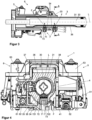
- the pretensioning device 7 is shown in detail in longitudinal section along the longitudinal axis L in Figure 3 shown, as well as in the cross section AA from Figure 3 , which in Figure 4 is shown enlarged.
- pretensioning devices 7 are arranged at a distance from one another in the longitudinal direction on the casing unit 3, which are essentially of the same construction, so that the features described below apply to each pretensioning device 7.
- the pretensioning device 7 has an adjusting screw 71 as an adjustable pretensioning element, which is screwed into an internal thread 34 in a radial bore 35 directed toward the longitudinal axis L.
- a pressure piece 72 is arranged on the adjusting screw 71 on the radially inwardly directed end face. The pressure piece 72 is movable in the bore 35 in the radial direction, toward the outside of the inner casing 31, and is supported in a form-fitting manner on the outer casing 33 in the circumferential and longitudinal directions.
- a spring element 73 namely a compression spring elastically deformable in the radial direction, such as a conical or corrugated spring washer, is arranged between the adjusting screw 71 and the pressure piece 72. It is also conceivable and possible to use other spring designs, such as disc springs or spiral springs.
- the pressure piece 72 has, on its inner side facing inwards away from the adjusting screw 71, a guide projection with two radially inwardly converging side flanks 721 and 722 in a wedge shape.
- the side flanks 721 and 722 each run parallel to the longitudinal axis L and delimit a prism-shaped cross-section converging at the wedge angle, which is oriented transversely to the longitudinal axis L; in other words, the tip of the wedge points radially inwards.
- An elongated guide groove 36 extending parallel to the longitudinal axis L is formed into the inner casing 31, preferably by cold forming, and is thus bead-shaped.
- the pressure piece 72, with its wedge-shaped cross section, radially engages the guide groove 36.
- the guide groove 36 has a V-shaped groove cross-section to which the pressure piece 72 is adapted, so that its side flanks 721 and 722 rest on the V-shaped converging inner sides of the guide groove 36, as in Figure 4 is recognizable.
- the adjusting screw 71 By screwing in, the adjusting screw 71 can be moved radially in the direction of the longitudinal axis L, whereby the pressure piece 72 is pressed radially from the outside into the guide groove 36 via the spring element 73 with a preload force F.
- the pressure piece 72 engages positively in the guide groove 36, with the wedge-shaped side flanks 721 and 722 being guided in a sliding manner in the longitudinal direction on the inner sides of the guide groove 36.
- the guide groove 36 thus functions as an elongated slide rail in which the pressure piece 72 can slide as a guided slide piece.
- the radial preload force F can be adjusted, with which the pressure piece 72 is preloaded in the guide groove 36.
- This allows the friction force to be adjusted and specified with small tolerances, which must be overcome as an adjustment force by the adjustment drive 6 for the telescopic length adjustment of the inner casing 31 relative to the outer casing 33.
- the circumferentially acting positive locking mechanism according to the invention creates a linear guide device in the longitudinal direction, which prevents rotation between the inner casing 31 and the outer casing 33.
- the invention creates an integrated preload guide device that combines the two functions of preload and guidance.
- the surfaces of the side flanks 721 and 722, which are in sliding contact with one another, and/or the inner sides of the guide groove 36, can preferably be designed to reduce friction, for example by being at least partially coated, at least on one side, with a plastic with good sliding properties, such as polytetrafluoroethylene (PTFE) or the like.
- PTFE polytetrafluoroethylene
- the preload force F can be set relatively high without impairing adjustment, and the rigidity of the casing unit 3 can be advantageously increased. It is further advantageous that the inventive combination of preload and guidance also increases, in particular, the torsional rigidity of the casing unit 33.
- radially inwardly projecting sliding surfaces 37 and 38 can be formed on the inner circumference, spaced in the circumferential direction from the pressure piece 72, which are spaced relative to one another in the circumferential direction and are opposite the pressure piece 72 with respect to the longitudinal axis L.
- the inner casing 31 is clamped in a defined three-point bearing between the sliding surfaces 37 and 38 and the pressure piece 72.
- two prestressing devices 7 are preferably arranged at a distance in the longitudinal direction. This allows an advantageously high bending stiffness and natural frequency of the shell unit to be achieved.
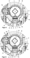
- FIG 5 is in cross-sectional view as in Figure 4 A second embodiment is shown enlarged.
- the rounded bearing surface 723 rests in two line contacts 724 in the guide groove 36, which also creates a positive connection in the circumferential direction.
- Figure 6 shows in the same view as Figure 5 a third embodiment, wherein the pressure piece 72 and the guide groove are modified.
- the pressure piece 72 has a guide groove 725, into which a radially outwardly projecting guide web 361 positively engages. which is formed in the cross-section of the guide groove 36. This creates the positive locking effect in the circumferential direction.
Landscapes
- Engineering & Computer Science (AREA)
- Chemical & Material Sciences (AREA)
- Combustion & Propulsion (AREA)
- Transportation (AREA)
- Mechanical Engineering (AREA)
- Steering Controls (AREA)
Claims (7)
- Colonne de direction (1) réglable par moteur pour un véhicule automobile, comprenant une unité d'enveloppe (3) dans laquelle un arbre de direction (30) peut être logé en rotation autour d'un axe longitudinal (L), et qui présente une enveloppe intérieure (31) disposée dans l'enveloppe extérieure (33) et télescopique par rapport à une enveloppe extérieure (33) dans la direction de l'axe longitudinal (L), et un entraînement de réglage (6) motorisé qui est couplé à l'enveloppe intérieure (31) et à l'enveloppe extérieure (33)un dispositif de précontrainte (7) étant prévu, lequel présente une pièce de pression (72) appuyée sur l'enveloppe extérieure (33) et pouvant être serrée contre l'enveloppe intérieure (31),le dispositif de précontrainte (7) présentant un dispositif de guidage coopérant avec la pièce de pression (72), pour le guidage linéaire de l'enveloppe intérieure (31) par rapport à l'enveloppe extérieure (33) dans la direction de l'axe longitudinal (L), le dispositif de guidage présentant des éléments à engagement positif (36, 721, 722, 723), le dispositif de guidage présentant un premier élément de guidage (36) sur l'enveloppe intérieure (31), et un deuxième élément de guidage (72, 721, 722, 723) correspondant à celui-ci sur la pièce de pression (72), qui est guidée de manière mobile sur le premier élément de guidage (36) dans la direction de l'axe longitudinal (L)caractérisé en ce queen ce que les éléments de guidage comprennent une rainure de guidage (36) formée d'un seul tenant par déformation plastique dans l'enveloppe intérieure (31) ou l'enveloppe extérieure (33) et réalisée sous la forme d'un renfoncement en forme de moulure, et une saillie de guidage (72, 721, 722, 723) qui s'y engage.
- Colonne de direction selon la revendication 1, caractérisée en ce que les éléments de guidage comprennent une glissière (36) et une pièce coulissante (72, 721, 722, 723) guidée de manière coulissante dans celle-ci.
- Colonne de direction selon la revendication 1 ou 2, caractérisée en ce que les éléments de guidage présentent des flancs latéraux (721, 722) convergeant en forme de coin transversalement à l'axe longitudinal (L).
- Colonne de direction selon l'une des revendications précédentes, caractérisée en ce que le dispositif de guidage est conçu de manière à réduire au moins partiellement la friction.
- Colonne de direction selon l'une des revendications précédentes, caractérisée en ce que le dispositif de précontrainte (7) est réglable.
- Colonne de direction selon la revendication 5, caractérisée en ce que le dispositif de précontrainte (7) peut être fixé dans une position de réglage prédéfinie.
- Colonne de direction selon l'une des revendications précédentes, caractérisée en ce que le dispositif de précontrainte (7) comporte un élément de ressort (73).
Applications Claiming Priority (2)
| Application Number | Priority Date | Filing Date | Title |
|---|---|---|---|
| DE102020203210.6A DE102020203210A1 (de) | 2020-03-12 | 2020-03-12 | Lenksäule für ein Kraftfahrzeug |
| PCT/EP2021/055704 WO2021180609A1 (fr) | 2020-03-12 | 2021-03-08 | Colonne de direction pour un véhicule automobile |
Publications (2)
| Publication Number | Publication Date |
|---|---|
| EP4117979A1 EP4117979A1 (fr) | 2023-01-18 |
| EP4117979B1 true EP4117979B1 (fr) | 2025-05-07 |
Family
ID=74870805
Family Applications (1)
| Application Number | Title | Priority Date | Filing Date |
|---|---|---|---|
| EP21711197.0A Active EP4117979B1 (fr) | 2020-03-12 | 2021-03-08 | Colonne de direction pour un véhicule automobile |
Country Status (3)
| Country | Link |
|---|---|
| EP (1) | EP4117979B1 (fr) |
| DE (1) | DE102020203210A1 (fr) |
| WO (1) | WO2021180609A1 (fr) |
Families Citing this family (6)
| Publication number | Priority date | Publication date | Assignee | Title |
|---|---|---|---|---|
| DE102020201058A1 (de) * | 2020-01-29 | 2021-07-29 | Thyssenkrupp Ag | Lenksäule für ein Kraftfahrzeug |
| DE102020206955B3 (de) * | 2020-06-03 | 2021-03-11 | Thyssenkrupp Ag | Lenksäule für ein Kraftfahrzeug |
| CN117957159A (zh) * | 2021-09-29 | 2024-04-30 | 杭州擎威科技有限公司 | 用于车辆的可调节转向柱 |
| DE102022121115A1 (de) * | 2022-08-22 | 2024-04-25 | Schaeffler Technologies AG & Co. KG | Längenverstellbare Bedieneinheit und Steer-by-Wire-System |
| CN115571215B (zh) * | 2022-11-10 | 2026-01-13 | 浙江极氪智能科技有限公司 | 管柱连接机构和车辆 |
| DE102024205259A1 (de) * | 2024-06-07 | 2025-12-11 | Zf Active Safety Gmbh | Lenksäule für ein Kraftfahrzeug und Montageverfahren |
Citations (1)
| Publication number | Priority date | Publication date | Assignee | Title |
|---|---|---|---|---|
| EP3299253B1 (fr) * | 2016-09-27 | 2019-04-17 | Aisin Seiki Kabushiki Kaisha | Dispositif de direction de vehicule |
Family Cites Families (5)
| Publication number | Priority date | Publication date | Assignee | Title |
|---|---|---|---|---|
| DE4008481A1 (de) | 1990-03-16 | 1991-09-19 | Reiche & Co | Als teleskoprohr ausgebildete, vorzugsweise durch handkraft hoehenverstellbare kraftfahrzeuglenksaeule |
| JP4433561B2 (ja) * | 2000-04-28 | 2010-03-17 | アイシン精機株式会社 | テレスコピックステアリング装置 |
| JP4255118B2 (ja) | 2003-09-29 | 2009-04-15 | 富士機工株式会社 | ステアリングコラムのガタ防止構造 |
| JP2013129322A (ja) * | 2011-12-21 | 2013-07-04 | Jtekt Corp | 保持構造及び保持構造の組立方法 |
| DE102018213679A1 (de) * | 2018-08-14 | 2020-02-20 | Thyssenkrupp Ag | Lenksäule für ein Kraftfahrzeug |
-
2020
- 2020-03-12 DE DE102020203210.6A patent/DE102020203210A1/de active Pending
-
2021
- 2021-03-08 EP EP21711197.0A patent/EP4117979B1/fr active Active
- 2021-03-08 WO PCT/EP2021/055704 patent/WO2021180609A1/fr not_active Ceased
Patent Citations (1)
| Publication number | Priority date | Publication date | Assignee | Title |
|---|---|---|---|---|
| EP3299253B1 (fr) * | 2016-09-27 | 2019-04-17 | Aisin Seiki Kabushiki Kaisha | Dispositif de direction de vehicule |
Also Published As
| Publication number | Publication date |
|---|---|
| DE102020203210A1 (de) | 2021-09-16 |
| WO2021180609A1 (fr) | 2021-09-16 |
| EP4117979A1 (fr) | 2023-01-18 |
Similar Documents
| Publication | Publication Date | Title |
|---|---|---|
| EP4117979B1 (fr) | Colonne de direction pour un véhicule automobile | |
| EP3619093B1 (fr) | Colonne de direction pour véhicule à moteur et procédé de fabrication d'une colonne de direction | |
| DE102012104644B3 (de) | Lenksäule für ein Kraftfahrzeug | |
| EP4365060B1 (fr) | Colonne de direction pour un véhicule automobile | |
| DE102009038317B4 (de) | Verstellbare Lenksäule für ein Kraftfahrzeug | |
| EP4222042B1 (fr) | Colonne de direction pour un véhicule automobile | |
| EP3242827B1 (fr) | Colonne de direction munie d'un siège de palier à montage flexible | |
| DE102022201101B3 (de) | Lenksäule für ein Kraftfahrzeug | |
| DE102012013970B4 (de) | Vorrichtung zum Andrücken einer Zahnstange an ein Ritzel | |
| DE102017223469A1 (de) | Motorisch verstellbare Lenksäule für ein Kraftfahrzeug | |
| EP2345569B1 (fr) | Engrenage hypoïde pour une direction d'un véhicule automobile | |
| EP3908499B1 (fr) | Colonne de direction pour un véhicule automobile | |
| EP3436329B1 (fr) | Colonne de direction pour véhicule automobile | |
| EP3880980B1 (fr) | Systeme de réglage pour une colonne de direction et colonne de direction pour un véhicule à moteur | |
| EP4172026A1 (fr) | Colonne de direction pour un véhicule motorisé et procédé d'ajustage d'une colonne de direction | |
| EP4179222B1 (fr) | Direction assistée pour un véhicule à moteur | |
| DE112019005339T5 (de) | Lenksäulenvorrichtung | |
| EP3911553B1 (fr) | Colonne de direction pour un véhicule automobile | |
| EP1737720B1 (fr) | Colonne de direction de securite pour automobile | |
| DE102006049808B4 (de) | Verstellgetriebe für eine Verstelleinrichtung | |
| EP4279357B1 (fr) | Système de direction pour un véhicule automobile | |
| EP4096988B1 (fr) | Colonne de direction pour un véhicule automobile | |
| EP3408159B1 (fr) | Colonne de direction pour un véhicule automobile | |
| DE102019209036B3 (de) | Kopplungselement zur Anbringung an einer Gewindespindel, Gewindespindel mit einem Kopplungselement, Spindeltrieb mit einer Gewindespindel und Lenksäule für ein Kraftfahrzeug mit einem Spindeltrieb | |
| DE102017212070A1 (de) | Zahnstangengetriebe für ein Kraftfahrzeug |
Legal Events
| Date | Code | Title | Description |
|---|---|---|---|
| STAA | Information on the status of an ep patent application or granted ep patent |
Free format text: STATUS: UNKNOWN |
|
| STAA | Information on the status of an ep patent application or granted ep patent |
Free format text: STATUS: THE INTERNATIONAL PUBLICATION HAS BEEN MADE |
|
| PUAI | Public reference made under article 153(3) epc to a published international application that has entered the european phase |
Free format text: ORIGINAL CODE: 0009012 |
|
| STAA | Information on the status of an ep patent application or granted ep patent |
Free format text: STATUS: REQUEST FOR EXAMINATION WAS MADE |
|
| 17P | Request for examination filed |
Effective date: 20221012 |
|
| AK | Designated contracting states |
Kind code of ref document: A1 Designated state(s): AL AT BE BG CH CY CZ DE DK EE ES FI FR GB GR HR HU IE IS IT LI LT LU LV MC MK MT NL NO PL PT RO RS SE SI SK SM TR |
|
| DAV | Request for validation of the european patent (deleted) | ||
| DAX | Request for extension of the european patent (deleted) | ||
| STAA | Information on the status of an ep patent application or granted ep patent |
Free format text: STATUS: EXAMINATION IS IN PROGRESS |
|
| GRAP | Despatch of communication of intention to grant a patent |
Free format text: ORIGINAL CODE: EPIDOSNIGR1 |
|
| STAA | Information on the status of an ep patent application or granted ep patent |
Free format text: STATUS: GRANT OF PATENT IS INTENDED |
|
| 17Q | First examination report despatched |
Effective date: 20240925 |
|
| INTG | Intention to grant announced |
Effective date: 20241024 |
|
| GRAS | Grant fee paid |
Free format text: ORIGINAL CODE: EPIDOSNIGR3 |
|
| GRAA | (expected) grant |
Free format text: ORIGINAL CODE: 0009210 |
|
| STAA | Information on the status of an ep patent application or granted ep patent |
Free format text: STATUS: THE PATENT HAS BEEN GRANTED |
|
| AK | Designated contracting states |
Kind code of ref document: B1 Designated state(s): AL AT BE BG CH CY CZ DE DK EE ES FI FR GB GR HR HU IE IS IT LI LT LU LV MC MK MT NL NO PL PT RO RS SE SI SK SM TR |
|
| REG | Reference to a national code |
Ref country code: GB Ref legal event code: FG4D Free format text: NOT ENGLISH |
|
| REG | Reference to a national code |
Ref country code: CH Ref legal event code: EP |
|
| REG | Reference to a national code |
Ref country code: DE Ref legal event code: R096 Ref document number: 502021007404 Country of ref document: DE |
|
| REG | Reference to a national code |
Ref country code: IE Ref legal event code: FG4D Free format text: LANGUAGE OF EP DOCUMENT: GERMAN |
|
| REG | Reference to a national code |
Ref country code: DE Ref legal event code: R084 Ref document number: 502021007404 Country of ref document: DE |
|
| REG | Reference to a national code |
Ref country code: NL Ref legal event code: MP Effective date: 20250507 |
|
| PG25 | Lapsed in a contracting state [announced via postgrant information from national office to epo] |
Ref country code: ES Free format text: LAPSE BECAUSE OF FAILURE TO SUBMIT A TRANSLATION OF THE DESCRIPTION OR TO PAY THE FEE WITHIN THE PRESCRIBED TIME-LIMIT Effective date: 20250507 Ref country code: PT Free format text: LAPSE BECAUSE OF FAILURE TO SUBMIT A TRANSLATION OF THE DESCRIPTION OR TO PAY THE FEE WITHIN THE PRESCRIBED TIME-LIMIT Effective date: 20250908 Ref country code: FI Free format text: LAPSE BECAUSE OF FAILURE TO SUBMIT A TRANSLATION OF THE DESCRIPTION OR TO PAY THE FEE WITHIN THE PRESCRIBED TIME-LIMIT Effective date: 20250507 |
|
| REG | Reference to a national code |
Ref country code: LT Ref legal event code: MG9D |
|
| PG25 | Lapsed in a contracting state [announced via postgrant information from national office to epo] |
Ref country code: NO Free format text: LAPSE BECAUSE OF FAILURE TO SUBMIT A TRANSLATION OF THE DESCRIPTION OR TO PAY THE FEE WITHIN THE PRESCRIBED TIME-LIMIT Effective date: 20250807 Ref country code: GR Free format text: LAPSE BECAUSE OF FAILURE TO SUBMIT A TRANSLATION OF THE DESCRIPTION OR TO PAY THE FEE WITHIN THE PRESCRIBED TIME-LIMIT Effective date: 20250808 |
|
| PG25 | Lapsed in a contracting state [announced via postgrant information from national office to epo] |
Ref country code: PL Free format text: LAPSE BECAUSE OF FAILURE TO SUBMIT A TRANSLATION OF THE DESCRIPTION OR TO PAY THE FEE WITHIN THE PRESCRIBED TIME-LIMIT Effective date: 20250507 Ref country code: NL Free format text: LAPSE BECAUSE OF FAILURE TO SUBMIT A TRANSLATION OF THE DESCRIPTION OR TO PAY THE FEE WITHIN THE PRESCRIBED TIME-LIMIT Effective date: 20250507 |
|
| PG25 | Lapsed in a contracting state [announced via postgrant information from national office to epo] |
Ref country code: BG Free format text: LAPSE BECAUSE OF FAILURE TO SUBMIT A TRANSLATION OF THE DESCRIPTION OR TO PAY THE FEE WITHIN THE PRESCRIBED TIME-LIMIT Effective date: 20250507 |
|
| PG25 | Lapsed in a contracting state [announced via postgrant information from national office to epo] |
Ref country code: HR Free format text: LAPSE BECAUSE OF FAILURE TO SUBMIT A TRANSLATION OF THE DESCRIPTION OR TO PAY THE FEE WITHIN THE PRESCRIBED TIME-LIMIT Effective date: 20250507 |
|
| PG25 | Lapsed in a contracting state [announced via postgrant information from national office to epo] |
Ref country code: RS Free format text: LAPSE BECAUSE OF FAILURE TO SUBMIT A TRANSLATION OF THE DESCRIPTION OR TO PAY THE FEE WITHIN THE PRESCRIBED TIME-LIMIT Effective date: 20250807 |
|
| PG25 | Lapsed in a contracting state [announced via postgrant information from national office to epo] |
Ref country code: IS Free format text: LAPSE BECAUSE OF FAILURE TO SUBMIT A TRANSLATION OF THE DESCRIPTION OR TO PAY THE FEE WITHIN THE PRESCRIBED TIME-LIMIT Effective date: 20250907 |
|
| PG25 | Lapsed in a contracting state [announced via postgrant information from national office to epo] |
Ref country code: LV Free format text: LAPSE BECAUSE OF FAILURE TO SUBMIT A TRANSLATION OF THE DESCRIPTION OR TO PAY THE FEE WITHIN THE PRESCRIBED TIME-LIMIT Effective date: 20250507 |
|
| PG25 | Lapsed in a contracting state [announced via postgrant information from national office to epo] |
Ref country code: DK Free format text: LAPSE BECAUSE OF FAILURE TO SUBMIT A TRANSLATION OF THE DESCRIPTION OR TO PAY THE FEE WITHIN THE PRESCRIBED TIME-LIMIT Effective date: 20250507 Ref country code: SM Free format text: LAPSE BECAUSE OF FAILURE TO SUBMIT A TRANSLATION OF THE DESCRIPTION OR TO PAY THE FEE WITHIN THE PRESCRIBED TIME-LIMIT Effective date: 20250507 |
|
| PG25 | Lapsed in a contracting state [announced via postgrant information from national office to epo] |
Ref country code: CZ Free format text: LAPSE BECAUSE OF FAILURE TO SUBMIT A TRANSLATION OF THE DESCRIPTION OR TO PAY THE FEE WITHIN THE PRESCRIBED TIME-LIMIT Effective date: 20250507 |
|
| PG25 | Lapsed in a contracting state [announced via postgrant information from national office to epo] |
Ref country code: EE Free format text: LAPSE BECAUSE OF FAILURE TO SUBMIT A TRANSLATION OF THE DESCRIPTION OR TO PAY THE FEE WITHIN THE PRESCRIBED TIME-LIMIT Effective date: 20250507 |
|
| PG25 | Lapsed in a contracting state [announced via postgrant information from national office to epo] |
Ref country code: SK Free format text: LAPSE BECAUSE OF FAILURE TO SUBMIT A TRANSLATION OF THE DESCRIPTION OR TO PAY THE FEE WITHIN THE PRESCRIBED TIME-LIMIT Effective date: 20250507 |
|
| PG25 | Lapsed in a contracting state [announced via postgrant information from national office to epo] |
Ref country code: IT Free format text: LAPSE BECAUSE OF FAILURE TO SUBMIT A TRANSLATION OF THE DESCRIPTION OR TO PAY THE FEE WITHIN THE PRESCRIBED TIME-LIMIT Effective date: 20250507 |
|
| REG | Reference to a national code |
Ref country code: DE Ref legal event code: R097 Ref document number: 502021007404 Country of ref document: DE |
|
| PLBE | No opposition filed within time limit |
Free format text: ORIGINAL CODE: 0009261 |
|
| STAA | Information on the status of an ep patent application or granted ep patent |
Free format text: STATUS: NO OPPOSITION FILED WITHIN TIME LIMIT |
|
| REG | Reference to a national code |
Ref country code: CH Ref legal event code: L10 Free format text: ST27 STATUS EVENT CODE: U-0-0-L10-L00 (AS PROVIDED BY THE NATIONAL OFFICE) Effective date: 20260318 |
|
| PGFP | Annual fee paid to national office [announced via postgrant information from national office to epo] |
Ref country code: GB Payment date: 20260324 Year of fee payment: 6 |
|
| PGFP | Annual fee paid to national office [announced via postgrant information from national office to epo] |
Ref country code: DE Payment date: 20260319 Year of fee payment: 6 |
|
| 26N | No opposition filed |
Effective date: 20260210 |
|
| PGFP | Annual fee paid to national office [announced via postgrant information from national office to epo] |
Ref country code: FR Payment date: 20260323 Year of fee payment: 6 |