EP4122623A1 - Transporteinheit für geschmolzenes metall und verfahren zum transport von geschmolzenem metall - Google Patents
Transporteinheit für geschmolzenes metall und verfahren zum transport von geschmolzenem metall Download PDFInfo
- Publication number
- EP4122623A1 EP4122623A1 EP21187380.7A EP21187380A EP4122623A1 EP 4122623 A1 EP4122623 A1 EP 4122623A1 EP 21187380 A EP21187380 A EP 21187380A EP 4122623 A1 EP4122623 A1 EP 4122623A1
- Authority
- EP
- European Patent Office
- Prior art keywords
- ladle
- transport unit
- axis
- tilting
- anyone
- Prior art date
- Legal status (The legal status is an assumption and is not a legal conclusion. Google has not performed a legal analysis and makes no representation as to the accuracy of the status listed.)
- Pending
Links
Images


Classifications
-
- B—PERFORMING OPERATIONS; TRANSPORTING
- B22—CASTING; POWDER METALLURGY
- B22D—CASTING OF METALS; CASTING OF OTHER SUBSTANCES BY THE SAME PROCESSES OR DEVICES
- B22D41/00—Casting melt-holding vessels, e.g. ladles, tundishes, cups or the like
- B22D41/12—Travelling ladles or similar containers; Cars for ladles
-
- B—PERFORMING OPERATIONS; TRANSPORTING
- B66—HOISTING; LIFTING; HAULING
- B66C—CRANES; LOAD-ENGAGING ELEMENTS OR DEVICES FOR CRANES, CAPSTANS, WINCHES, OR TACKLES
- B66C17/00—Overhead travelling cranes comprising one or more substantially horizontal girders the ends of which are directly supported by wheels or rollers running on tracks carried by spaced supports
- B66C17/06—Overhead travelling cranes comprising one or more substantially horizontal girders the ends of which are directly supported by wheels or rollers running on tracks carried by spaced supports specially adapted for particular purposes, e.g. in foundries, forges; combined with auxiliary apparatus serving particular purposes
- B66C17/10—Overhead travelling cranes comprising one or more substantially horizontal girders the ends of which are directly supported by wheels or rollers running on tracks carried by spaced supports specially adapted for particular purposes, e.g. in foundries, forges; combined with auxiliary apparatus serving particular purposes for transporting ladles
Definitions
- the invention refers to a generally automated process for liquid or molten metal transport from a ladle change unit to a furnace and back to the ladle change unit.
- the invention further refers to a respective ladle transport unit, which can be used in the process to transport the liquid or molten metal, wherein the area of operations of the ladle transport unit is restricted to the melting shop of a foundry plant.
- EP 2 427 283 B1 refers to a process wherein a receptable for liquid metal is connected to a forklift-like apparatus, which can vertically move the receptable.
- the apparatus with the receptable collects liquid metal from a furnace. From the furnace the apparatus drives to a hand-over point, tilts the receptable, and pours the liquid metal from the receptable into a ladle connected to a second forklift-like apparatus which moves the ladle towards the moulding plant.
- US 2017/0232507 A1 refers to a process to deliver liquid metal in a foundry plant from a furnace to moulds of a moulding plant, wherein a ladle is moved by a first apparatus from a first hand-over point through the melting shop, and back to first the hand-over point. At the first hand-over point the filled ladle is transferred to a second apparatus which drives the ladle to a second hand-over point where it is transferred to a pouring machine.
- the first apparatus can move the ladle vertically and horizontally to compensate for different filling levels of the furnace.
- the proposed plant needs a lot of space and due to the multiple hand-over point is susceptible to failure resulting in high maintenance efforts.
- the objective is solved by the ladle transport unit according to claim 1 and the method for liquid or molten metal transport according to claim 16.
- the ladle transport unit comprises a base with a power supply unit and preferably a motor which moves the ladle transport unit on a flat or even surface or on rails preferably mounted on a flat or even surface along a first axis in a first direction and a second direction.
- the second direction is opposite to the first direction, preferably along a horizontal.
- the power supply unit can be a control cabinet or control box. Less preferable the power supply can comprise a battery, especially a rechargeable battery.
- the ladle transport unit further comprises a control system, comprising for example specified interfaces for signal exchange, preferably wireless. Signals can be exchanged with a remote device, such as a central controller, a cloud, a processing station of the foundry plant, or a portable device, for example a mobile phone. Signals can be sent and/or received.
- the control system can comprise a computer unit to process the signals received and/or the signals to be sent.
- the control system can initiate, control, and stop the movements of the ladle transport unit and all parts connected to it according to a program stored in a ROM or RAM.
- the program stored can be started, stopped, and optionally amended from a remote input device, such as a mobile with a touchscreen. All data measured and processed by the control system can be stored in a memory to allow tracing of each single activity.
- the ladle transport unit comprises a ladle lifting device connected to or supported by the base, wherein the ladle lifting device can be rotated about a second axis perpendicular to the first axis, especially vertically directed.
- the ladle lifting device has a ladle lifting portion and a ladle tilting portion.
- the ladle tilting portion is connected to the ladle lifting portion, wherein the ladle tilting portion can move relative to the ladle lifting portion along a third axis perpendicular to the first axis in a third direction and a fourth direction.
- the fourth direction is opposite the third direction, preferably along a vertical.
- the ladle tilting portion can be or can comprise a vertical adjustment slide connected to the ladle lifting portion.
- the ladle lifting device of the ladle transport unit can be a composition of a rotatable socket (ladle lifting portion) and a vertically moveable slide or sledge (ladle tilting portion).
- a ladle tilting device is connected to the ladle tilting portion, wherein the ladle tilting device can rotate about a fourth axis perpendicular to the third axis relative to the ladle lifting portion.
- the ladle tilting device can rotate in clockwise and in anticlockwise direction.
- the ladle transport unit further comprises a connecting device to safely connect a ladle to the ladle transport unit.
- the connection device is formed on a free end of the ladle tilting device.
- the connecting device comprises a locking arrangement comprising at least three connecting members forming a three-point connection.
- the connecting device and the relationships and functions of the at least three connecting members are described in a coordinate system comprising an x-, y- and z-axis which define a space.
- the x-y-axes define the horizontal plane.
- the y-axis runs parallel to the first movement axis of the ladle transport unit
- the x-axis is a horizontal axis perpendicular to the y-axis
- the z-axis is a vertical axis perpendicular to the x-axis and the y-axis and runs parallel to the rotatable second axis A2 of the ladle transport unit.
- the x-, y-, and z-axes extend in a positive axis-direction x(+), y(+), and z(+), and a negative axis-direction x(-), y(-), and z(-).
- the respective coordinate system is illustrated in Figures 2a and 2b , wherein the represented coordinate system is the same, once viewed onto the ladle and once viewed onto the connecting device for connecting the ladle.
- a first connecting member may be formed to adjust a position of the ladle along a vertical axis in z(-) direction on the ladle transport unit and preferably also in a horizontal distance between the ladle and a surface of the ladle tilting device facing the ladle.
- a second connecting member may be formed to adjust a position of the ladle along a vertical direction in z(-) direction, along a first horizontal direction (both y-directions y(+) and y(-)), running perpendicular to the third axis A3 of the ladle transport unit, and along a second horizontal direction (both x-directions x(+) and x(-)), running perpendicular to the third axis A3 of the ladle transport unit, and preferably also in a horizontal distance (in y(+) direction) between the ladle and the surface of the ladle tilting device facing the ladle.
- a third connecting member may be present and adds a locking function for the ladle.
- two connecting members have holding functions and one has a locking function.
- the first connecting member and the second connecting member can be connected to the ladle tilting device in its non-tilted position near an upper end of the surface facing the ladle, while the third connecting member can be connected to the ladle tilting device near a lower end of its surface, preferably in a horizontal middle-position.
- the first connecting member can be a metal block connected to the ladle tilting device with a funnel-shaped slot extending downwards from an upper side of the metal block.
- the ladle can comprise a plate-like engagement part which engages the funnel-shaped slot.
- the second connecting member can be a knob-shaped seat extending from the surface of the ladle lifting device facing the ladle in horizontal direction, generally parallel to the fourth axis.
- the seat can have cross-sections of different diameters perpendicular to the horizontal direction. While the free end of the seat and the end of the seat connected to the ladle tilting device can comprise equal or different diameters, a section between the two ends can have a diameter which is smaller than any diameter of the two ends, forming a slot, preferably a circumferential slot. At least one sidewall of the slot can be bevelled to form a guide in y-direction for a fork-like engagement part comprised by the ladle.
- the third connecting member can be or can comprise a frame-shaped locking element.
- the third connecting member connects to the surface of the ladle tilting device facing the ladle in a pivot point.
- a pivot axis of the pivot point can be horizontal parallel to the first axis A1 and perpendicular to the second axis A2.
- the locking element prevents the ladle to move relative to the ladle tilting device in z(+) direction during rotational movement around the fourth axis A4 and thus connects the ladle to the ladle transport unit safely in all angular positions.
- the third connecting member has a locking element that is moveable from a first position (unlocked position) into a second position (locked position), and vice versa.
- the movement within the third connecting member is executed by e.g. an electric cylinder which tilts the locking element towards the ladle to establish the lock and in the opposite direction to release the lock.
- the locked third connecting member locks the ladle against movement in z(+) direction. This may also called a "blocking" in z(+) direction.
- the shape of the locking element may have several forms, corresponding to the complement of the counter-blocking element at the ladle.
- the ladle transport unit is operated completely electrically and comprises at least an electric motor, preferably one electrical motor for each of the first to the fourth axis.
- the ladle transport unit may comprise at least one electric motor for driving the wheels, each wheel, or each drive shaft of the ladle transport unit. The absence of any hydraulic component in the ladle transport unit helps to achieve the aim of efficient and clean production, susceptibility of the unit and reduces maintenance efforts.
- the ladle lifting device can rotate about the second axis from a start position to a first end position and to a second end position.
- a horizontal longitudinal axis of the ladle lifting device runs parallel to the first axis.
- the horizontal longitudinal axis of the ladle lifting device runs perpendicular to the first axis. That means, the ladle lifting device can generally rotate about ⁇ 90° from the angular start position to the first or second angular end position.
- the total angular moving range of the ladle lifting device is generally 180°.
- the total angular moving range of the ladle lifting device between the start position and the first and second end position is generally 90°, or 60° or less.
- the connecting device comprises at least one holding member, for example a hook-like holding member to grip the ladle and/or at least one alignment member to correct a misalignment of the ladle relative to the ladle transport unit, and/or at least one locking member to safely lock the ladle to the ladle transport unit.
- at least one holding member for example a hook-like holding member to grip the ladle and/or at least one alignment member to correct a misalignment of the ladle relative to the ladle transport unit, and/or at least one locking member to safely lock the ladle to the ladle transport unit.
- the ladle transport unit may further comprise a fifth axis which runs parallel to the rotational fourth axis.
- the ladle lifting device and/or the tilting device or ladle tilting device can be moved linearly along the fifth axis.
- the ladle lifting device and the ladle tilting device can be moved along the fifth axis together as one single part.
- the ladle lifting device and the ladle tilting device can be moved relative to each other along the fifth axis.
- the ladle lifting device and the ladle tilting device move a first distance together, then the ladle lifting device stops and the ladle tilting device can move further along the fifth axis relative to the ladle lifting device.
- the fifth axis can be driven by an additional electric motor or by the motor of the fourth axis via a respective coupling.
- the locking member described above is preferably a safe ladle lock-in mechanism which cooperates with a respective lock of the ladle when the ladle is connected to the ladle transport unit.
- the locking member is preferably designed in such a way that it can hold the ladle during a rotation around the fourth axis.
- the locking member can be connected to the ladle tilting device in a swivel fitting with a horizontal swivel axis orientated perpendicular to the fourth axis.
- the locking movement of the third locking member can be executed when the ladle is connected to the ladle transport unit in the ladle change unit in a transport position. Alternatively, the locking movement can be executed whenever the ladle tilting device receives a signal from the controller to start a tilting movement, and locking may disengage as soon as the ladle is back in its transport position.
- the ladle transport unit can comprise 4 + 1 axes, wherein all axes are controlled by a controller of the control system.
- the controller can be integrated in the ladle transport unit, comprising a receiver unit to receive signals from remote device.
- the signals can initiate a program to start the ladle transport unit and control all movements of the ladle transport unit through a liquid metal shop. This is also called "the process”.
- the controller may be customised to exchange data with at least selected process-stations in the melting shop, such as one or more supply furnaces (that supply molten metal), a liquid metal treatment station, and a ladle change unit.
- the controller may comprise devices to store data, devices to process data, at least one interface to receive data from a remote device, and at least one interface to send data to a remote device, such as a mobile phone or any other display.
- the ladle transport unit comprises a weight measuring device to sense a weight or a change of weight of a connected ladle.
- the measuring device can be connected to the base and/or to the ladle tilting portion or ladle tilting device.
- the weight measuring device comprises at least three measuring sensors.
- the weight measuring sensors can be internal with the ladle tilting device and/or in contact with the axle of the rotational fourth axis.
- the weight measuring sensors are positioned on the connecting parts which connect the ladle tilting portion to the ladle lifting portion of the ladle lifting device in a moveable manner, such as a slide for example. If the ladle tilting portion moves vertically along the third axis relative to the ladle lifting portion the weight measuring sensors move together with the ladle tilting portion.
- the weight of the ladle with or without the liquid metal can be measured fail-safe independent of the angular position of the ladle tilting device with the ladle being connected to the ladle tilting portion.
- the ladle transport unit comprises four, six, eight or more connecting parts connecting the ladle tilting portion moveably to the ladle lifting portion.
- the number of the weight measuring sensors can correspond to the number of the connecting parts.
- the ladle lifting device can be prepared to hold a counterweight to compensate a weight of a ladle, especially a ladle which has been filled with the liquid or molten metal.
- the counterweight may be releasably connected to the ladle lifting device such that the weight of the counterweight can be customised to the total weight of the filled ladle to be transported.
- the full counterweight may be split into several portions that may be stacked.
- the counterweight can prevent tipping over of the ladle transport unit in the first and second end position, especially with the ladle in a raised position, due to the weight of the ladle filled with liquid or molten metal. At the same time the counterweight reduces or eliminates the effect of the weight of the filled ladle on the second axis, which could result in jamming of the ladle lifting device, a higher power consumption, or even a defect of the ladle transport unit.
- the melting shop can comprise a weight changing station.
- the ladle transport unit can be moved to the weight changing unit in the melting shop to adjust the weight to the weight of liquid metal to be filled in the ladle at the furnace for a production.
- the weight changing station can comprise a storage for weight(s). Taking off weights as well as adding weights to the ladle transport unit can be done automatically or half-automatically, controlled by staff.
- Adopting the weight carried by the ladle transport unit to the weight of the liquid metal transported from the furnace to the ladle change unit saves energy and reduces cost of the process.
- the ladle transport unit comprises at least one sensor to detect obstacles in the way of movement.
- the sensor can especially detect obstacles lying on the floor or persons or objects crossing the way of the moving ladle within a given safety zone.
- the ladle transport unit comprises at least two sensors, one sensor for each moving direction along the first axis. More sensors can be used to detect obstacles extending in the way of transport from the side or from above. Generally, the number of sensors is not limited.
- the sensors when activated provide a permanent interference check to avoid collision with any obstacle on the ground or extending from the side or from above into the space covered by the ladle transport unit with the ladle.
- the sensors create a two-dimensional safety zone in the direction of movement of the ladle transport unit.
- the sensors can alternatively create a three-dimensional safety zone around the ladle transport unit.
- the sensor(s) send a respective signal or respective signals to the controller or the control system.
- a calculator of the control system can evaluate the likeliness of a collision of the ladle transport unit with the detected obstacle. If a collision is possible the control system initiates a slow-down or stop of the ladle transport unit and generates an alarm to inform the staff about the problem.
- the sensor can especially be a laser scanner or an imaging method, such as a camera.
- the sensor or the sensors or the control system may create a first security zone for the ladle transport unit with the empty or poured ladle, and a different, second security zone for the ladle transport unit with the ladle filled with liquid metal.
- the second security zone may have a greater dimension than the first security zone.
- a breaking distance in the second security zone may be longer, which allows breaking the heavier ladle transport unit to a standstill with a smaller negative acceleration.
- the dimension of the second security zone and the maximum negative acceleration of the ladle transport unit in the second security zone should be such that a molten or liquid metal inside a ladle connected to the ladle transport unit does not spill over during braking of the ladle transport unit as a reaction of the detection of an obstacle. Spilling over should be avoided in any situation, including an emergency stop.
- the connecting device especially a front surface of the connecting device comprises a key element to match with a counter-key element of a respective ladle.
- the connecting device may comprise only one, or two, three or more keys (and the same number or less counter-key elements provided on the ladle).
- the keys or key elements may be sensors, such as touch switches, press keys or orifices of identical or different shape. If more than one key element is provided, each of the key elements can be activated independent from any of the other key elements.
- the key elements identify, especially bi-unique identify the ladle connected to the ladle transport unit by means of individual counter-key elements on the ladle. If the ladle cannot be identified as the ladle expected according to the production plan, the controller will not start a new cycle but inform the staff that an unknown ladle has been delivered to the ladle change unit.
- the ladle transport unit may comprise an identification system, such as a barcode, to identify a ladle by an identification label connected to an outer surface of the ladle facing the identification system if the ladle transport unit is in position to be connect to the ladle. This allows detection of a ladle prior being connected to the ladle transport unit and thus allows for an early correction.
- an identification system such as a barcode
- the ladle lifting device when being rotated about the second axis can be fixed in several rotational positions. Fixation may be provided in different angles of rotation, for example in the 0° position for linear movement of the ladle transport unit along the first axis or in the ⁇ 90° positions for filling the ladle with liquid metal at the furnace, treating of the molten metal in a metal treatment station, and ladle change in the ladle change unit, for example.
- the ladle lifting device can generally be fixed in any rotational position. Fixation of the ladle lifting device is preferably an electrical fixation by the electrical motor. To fix the motor in a certain rotational position the power to the motor can simply cut off to activate a motor holding break.
- the rails may be of the encapsulated type.
- energy supply is connected under-floor to the rails. This allows quick, unhindered access to the furnace or furnaces for the staff in the case of a process-stop due to a failure in at least one of the furnaces. The effect can be shortened down times of the melting shop positively influencing the production costs.
- the rail runs generally parallel to the furnaces along a straight line. Opposite to the furnaces with respect to the rail can be positioned at least one of the ladle emptying station, the ladle metal treatment station, and the ladle change unit, for example.
- the result is a compact melting shop.
- Another aspect of the invention refers to a method for liquid metal transport with a ladle, see claim 16.
- the method comprising the steps of taking a poured or empty ladle from a ladle change unit using a ladle transport advise; moving the ladle transport device with the poured ladle to a ladle emptying station and emptying molten metal remained from the ladle; moving the emptied ladle to a heating station to heat the empty ladle; filling the emptied ladle at the furnace with the molten or liquid metal; driving the ladle transport device with the filled ladle to a liquid metal treatment station and starting treatment; optionally measuring the temperature of the liquid metal at the furnace and/or prior starting or during the treatment process; stopping treatment and deslagging the treated liquid metal; taking a sample and measuring the temperature of the treated liquid metal; and driving the ladle transport device with the ladle back to the ladle change unit.
- the ladle can be turned over by more than 180° by the ladle tilting device.
- the step of deslagging is performed in or near the metal treatment station.
- deslagging is performed by hand.
- the temperature of the liquid metal can be measured, a sample of the liquid metal can be taken to control the quality of the untreated and/or treated liquid metal.
- Treatment can comprise adding of at least one finishing-meatal of Mg, Si, Al, and Cu. If necessary, pigging can be executed inside the metal treatment station. No treatment is necessary if the process concerns grey cast iron.
- the ladle While treating the metal in the treatment station the ladle may be covered by a lid, wherein the lid can be a functional lid which performs steps of the treatment, like providing an additive or additives to the liquid metal to improve quality, stirring the liquid metal, introducing additional temperature, etc.
- the ladle can be tilted in the metal treatment station to facilitate handling during sample taking or deslagging or inserting a temperature measuring sensor.
- the tilting of the ladle results in an easy handling, especially if deslagging and/or sampling is performed manually.
- the tilting angle can be 60° or less, preferably at most 30°.
- the weight of the ladle with the liquid metal flowing into it may be monitored permanently.
- the ladle weight is controlled or monitored wireless.
- the amount of molten metal needed for the next production in a linked moulding plant can be precisely measured.
- Precise measuring of the weight of the liquid metal taken from the furnace as one component of a final material helps to produce subsequent charges in reproduceable quality for production of same parts.
- the temperature of the liquid metal flowing out of the furnace can be measured by a sensor, such as an optical sensor.
- the weight measuring device of the ladle transport unit may communicate via the control unit, such as a plant control unit with the furnace to stop the delivery of liquid metal when the requested amount of liquid metal has been received in the ladle.
- the control unit such as a plant control unit with the furnace to stop the delivery of liquid metal when the requested amount of liquid metal has been received in the ladle.
- the temperature of the liquid metal inside the ladle can be controlled permanently, to control the cooling rate of the liquid metal on its way from the furnace to the moulding plant.
- the ladle comprises a lid, as it is preferred, the lid gets separated from the poured or empty ladle at or in the ladle change unit after being connected to the ladle transport unit and prior leaving the ladle change unit.
- the lid can be put on the filled ladle at or in the ladle change unit after arrival of the filled ladle at the ladle change unit and prior to being disconnected from the ladle transport unit.
- the step of separation from and re-connection of the lid to the ladle can involve lifting/lowering and/or laterally displacing of the ladle relative to a hook shaped grip that engages bars at the lid.
- the respective movements of the ladle are executed by the ladle transport unit.
- the ladle comprises a lid and the ladle is covered by a lid in the treatment station, the ladle with the liquid metal is only open to the environment on the way from the furnace to the treatment station and on the way from the treatment station to the ladle change unit.
- the geometric form of the filling space for liquid metal in the ladle for example a cylindric form, covering the ladle as described results in a minimum temperature loss of the liquid metal on its way through the plant.
- the sequence of the steps of the process is initiated by a process control unit.
- the process control unit can be activated for the first step or for the first and any subsequent step by hand and/or by another device, such as the furnace, the metal treatment station, or the ladle change unit.
- the furnace initiates liquid metal supply to the next ladle or starts the next cycle if the metal inside the furnace has reached a predetermined temperature level but will not deliver liquid metal at a different or lower temperature. It may as well mean that a cycle gets initiated from the metal treatment station if conditions in the metal treatment station allow proceeding.
- the ladle change unit can initiate a cycle as soon as an empty or poured ladle has been provided and/or the ladle is connected to the ladle transport unit, after a positive identification.
- the decision which device initiates the next cycle may be decided automatically by a central controller, or manually, for example via an input device showing the condition of all devices crucial for the production.
- the moulding plant may stop the process in the melting plant if defect moulds or other defaults in the moulding plant are detected.
- the result is a just in time production, wherein the treated liquid metal is only supplied if all devices are working, and the liquid metal provided can be processed in time.
- the ladle transport device used in the process may be the ladle transport unit according to the first aspect of the invention.
- the described method allows monitoring of real time data by a liquid management system and a calculated and controlled treatment ensuring an optimum iron quality.
- liquid metal and "molten metal” used throughout the description refer to the same product, viz. the metal taken from the furnace for further processing.
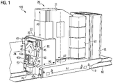
- Figure 1 refers to an embodiment of a ladle transport unit 100.
- the ladle transport unit 100 has a compact construction.
- the ladle transport unit 100 is part of a melting shop of a foundry plant.
- the melting shop would not comprise in this disclosure a PP (pouring process) as shown in Figure 3 at the bottom.
- the disclosure here handles transport and the provision of molten metal in a ladle to deliver it to such a process PP or receive it back from such PP process.
- the ladle transport unit 100 comprises a base 10.
- the base 10 comprises a power unit or power supply unit 15 to control the movements of the ladle transport unit 100.
- the power supply unit 15 controls at least a first electrical motor.
- the ladle transport unit 100 moves on a plane ground or, as it is preferred, on rails 60.
- the advantage of moving the ladle transport unit 100 on plane ground is that the directions of movement are only restricted by the plane area.
- the advantages of moving the ladle transport unit 100 along rails 60 is easy control of the track and improved safety.
- the rails 60 are of the encapsulated type, positioned underneath the plant-floor.
- the ladle transport unit 100 comprises a controller or a control system which controls all movements of the ladle transport unit 100 and the parts connected to it, as will be described later.
- the controller or the control system can be linked to a shop or plant central control system and be able to receive signals from this central control system or to send signals to the central control system.
- control system and the central control system will not be described in detail, as those systems are known to the skilled person.
- the base 10 further comprises at least one sensor 70 or several sensors 70, for example at least one sensor 70 for a movement in a first direction and one sensor 70 for a movement in a second direction.
- the sensors 70 permanently monitor the environment of the moving ladle transport unit 100 to detect obstacles the ladle transport 100 unit could collide with while moving.
- the sensor(s) 70 If an obstacle is detected the sensor(s) 70 generate(s) a warning signal and or send respective digital information to the control system or central control system.
- the control system or central control system identifies the position of the obstacle, informs the staff, and decides whether to slow down or stop the ladle transport unit 100 automatically.
- the staff eliminates the obstacle and restarts normal operational mode of the running process, if necessary.
- the controller can decide whether the liquid metal in the ladle requires special treatment in the liquid metal treatment station, such as introducing additional heat, or if the liquid metal inside the ladle must be disposed, for example emptied in a ladle emptying station. If the cooled liquid metal cannot be further processed, the melting shop starts a new cycle, preferably beginning at the furnace.
- the base 10 can further comprises a flashlight indicating that the ladle transport unit 100 is moving, for example (not shown).
- a ladle lifting device 20 Attached to an upper surface of the base 10 is a ladle lifting device 20, comprising a ladle lifting portion 21 and a ladle tilting portion 22.
- the ladle lifting device 20 is rotatably mounted to the base 10 and rotates relative to the base 10 around an axis A2 directed perpendicular to the upper surface of the base 10.
- the ladle lifting device 20 may rotate clockwise and anticlockwise about an angle of generally ⁇ 90°, from the position indicated in Figure 1 .
- the ladle lifting device 20 comprises a second motor for the rotational movement.
- the second motor is an electrical motor.
- the ladle lifting device 20 can be fixed in at least one position, preferably in several angular positions. In the fixed mode the ladle lifting device 20 cannot rotate about the rotational axis A2. Preferably the fixation of the ladle lifting device 20 is electric.
- the ladle tilting portion 22 forms a carriage guide with the ladle lifting portion 21 for a movement along a third axis A3 perpendicular to the first axis A1 and parallel to the second axis A2.
- a third motor operates the ladle tilting portion 22 along the third axis A3.
- the third motor is an electrical motor.
- the ladle tilting device 30 is rotatably attached to the ladle tilting portion 22 of the ladle lifting device 20 and swivels around a fourth axis A4.
- the fourth axis A4 extends perpendicular to the third axis A3 and parallel to the first axis A1, when the ladle lifting device 20 is in the shown start position.
- a fourth motor rotates the ladle tilting device 30 around the fourth axis A4.
- the fourth motor is an electrical motor.
- the ladle lifting device 20 and the ladle tilting device 30 can be linearly moved relative to the base 10 along a fifth axis A5 parallel to the fourth axis A4.
- the ladle lifting device 20 and the ladle tilting device 30 can move as a single body along the fifth axis A5.
- the ladle tilting device 30 can move along the fifth axis A5 relative to the ladle lifting device 20.
- the ladle lifting device 20 and the ladle tilting device 30 can move in a first movement along the fifth axis A5 as one body and the ladle tilting device 30 can move in a second movement along the fifth axis A5 relative to the ladle lifting device 20.
- the free end of the ladle tilting device 30 is closed by a cap 45 or inspection plate which shields the inside of the ladle tilting device 30 from lost heat of the ladle and fouling.
- the connecting device safely connects a ladle L (shown in Figure 2b ) to the ladle transport unit 10 respectively the ladle tilting device 30.
- the connecting device has three members 40, 41, 43. In this example it comprises a compensating or centring member 41 which corrects a misalignment between the ladle and the ladle transport unit 100 while connecting the ladle to the ladle transport unit 100, a supporting member 40, to grip the ladle, and a locking member 43 to safely "clinch" the ladle L - not shown in Figure 1 - during its rotation about the fourth axis A4.
- the ladle tilting device 30 further comprises an identification device 42 to identify each ladle connected to it.
- the identification device 42 of the embodiment shown comprises several keys which cooperate with at least one counter-key provided on the ladle. A certain combination of keys and counter-key represent a specific ladle. Thus, each ladle can be identified individually.
- the information concerning any actual combination of keys and counter-keys can be sent to the control system or the central controller system to control if the ladle connected to the ladle transport unit 100 is the ladle which must be connected according to the production plan.
- the keys of the identification device 42 can be press keys which can be pressed individually by respective areas of the ladle and/or orifices to receive the counter-keys connected to the ladle.
- the keys 42 and counter-keys are not restricted to the described embodiments.
- the ladle transport unit 100 can comprise a second identification system (not shown), such as a wand reader, to read a code of a label connected to the surface facing the ladle transport unit 100.
- Identifying the ladle by the label can alternatively be performed in a ladle change unit prior connecting the ladle to the ladle transport unit 100.
- the ladle will not be connected to the ladle transport unit 100 if it is detected that the identification of the provided ladle is not identical with the identification stored in the control system or the central control system.
- the above-mentioned locking member 43 in the embodiment illustrated in Figure 1 can have a element that tilts around a tilting axis A6 perpendicular to the rotational axis A4 of the ladle tilting device 30 and perpendicular to the linear axis A2 of the ladle lifting device 20.
- the ladle can be filled with liquid metal having a weight of approximately three tons (3.000kg).
- the ladle transport unit 100 comprises a counterweight 50 which is arranged adjacent to the ladle lifting portion 21 opposite to the ladle tilting portion 22.
- the counterweight 50 has segments, shown are four stacked counterweight portions, releasably connected to the ladle lifting unit 20, i.e., the ladle lifting portion 21.
- the weight of the counterweight 50 can be adjusted to the planned weight of the ladle filled with liquid metal for a process to save energy if the weight of the filled ladle allows for a lighter counterweight 50.
- its rotation around the second axis A2 will also rotate the counterweight 50.
- the ladle transport unit 100 can comprise a weight measuring device 44 to sense a weight of the ladle or to sense a weight change of the ladle while liquid metal is filled into the ladle.
- the weight measuring device 44 preferably measures continuously the weight if the pouring in liquid metal and can send the measured weight in real-time to the controller.
- the controller e.g., the PCU of Figure 2 stops feeding of liquid metal from the furnace if the weight of the ladle corresponds to a value stored in the controller for the present production task.
- FIG 2 shows in Figure 2a the detail of one embodiment of the locking arrangement, which is comprised by the ladle tilting device 30 of the ladle transport unit 100.
- the tilting device 30 is in a position in which it can be connected to a ladle in the ladle change unit.
- Figure 2b shows an example of a ladle which can be connected to the ladle transport unit 100 via the locking arrangement.
- the ladle illustrated in Figure 2b is not part of the invention and is only presented to point out the functionality of the connecting device.
- a coordinate system is added wherein the coordinate systems helps to understand the functioning of the connecting device.
- the coordinate system comprises the axes x, y, and z. Each axis extends from a common intersection point in a plus-direction (+) and a minus-direction (-).
- the connecting device of Figure 2a comprises three connection members 40, 41, and 43 which form a three-point connection, wherein two of the connection members 40, 41 mainly carry the load of a connected ladle.
- First connection member 40 fixes the connected ladle in negative z-direction z(-) and in both y-directions y(+) and y(-).
- Second connecting member 41 fixes the connected ladle additionally in both x-directions x(+) and x(-), in the negative z-direction z(-), and in both y-directions y(+) and y(-).
- the first connection member still allows movement in both x-directions and the positive z-direction.
- the second connecting member allows movement in the positive z-direction only.
- the first connection member 40 and the second connection member 41 are firmly fixed to the ladle tilting device 30, so that they cannot be moved relative to the ladle tilting device 30 while the ladle transport unit 100 is used in the melting shop.
- the third connecting member 43 has a locking element 43a which blocks the connected ladle in z(+) direction and thus allows safe tilting of the ladle connected to the ladle tilting device.
- the third connecting member 43 comprises a base 43c which is fixed to the ladle tilting device 30.
- the base 43c has a slit 43b which runs generally parallel to the surface of the cap 45, or to the slit of the first connecting member 40, and a through hole in the base 43c underneath the slit 43b.
- the locking element 43a is connected to the base 43c through a swivel axis A6 accommodated in the through hole.
- the locking element 43a can be moved towards the ladle tilting device 30 and away from it, wherein the third connecting member 43 locks the ladle to the ladle transport unit LTU 100 with the locking element 43a in a first position and releases the ladle in a second position.
- the third locking element 43a has a frame-like shape. This frame-like shape encompasses at least partially the plate 43p fixed at the ladle L as seen in Figure 2b as the counter blocking element.
- an identification device 42 comprising several sensors, such as touch switches or press keys, to identify a ladle getting connected to the ladle transport unit 100.
- Figure 2b shows one example of a ladle which could be connected to the ladle transport unit illustrated in Figure 1 via the locking arrangement.
- the ladle comprises the counter-elements 40p, 41p and 43p which cooperate with the connecting members 40, 41, 43 to safely connect the ladle to the ladle transport unit 100.
- the counter-element 40p With the ladle connected to the ladle transport unit the counter-element 40p rest in the slit of the first connecting member 40, the counter-element 41p partially encompasses the second connecting member 41, and the counter-element 43p reaches into the slit 43b of the base 43c of the third connecting member 43 and is at least partially encompassed by the locking element 43a in the locked condition or position, preferably by the horizontal portion of the frame-like locking element 43a.
- Figure 2b also shows the counter-element 42p to the identification device 42 comprising a nose directed downwards which can activate one or more of the several sensors of the identification device 42.
- the position and the vertical extension of the downwardly directed nose on the counter-element 42p can be varied to positively identify each ladle of several ladles.
- FIG 3 shows an example of a design of a melting shop.
- the melting shop MS comprises a couple of furnaces F1, F2, F3, F4, which liquidise or melt metal and keep it in the liquid or molten condition.
- Each furnace F1, F2, F3, F4 comprises at least one discharge point DP where the liquid metal is transferred (in fact poured) into a ladle L provided there by the ladle transport device LTD, e.g., as explained as unit 100 above.
- the furnace F comprises several discharge points, and one is used for supply to a ladle L.
- the melting shop further comprises a liquid metal treatment station MTS.
- the liquid metal inside the ladle L can be treated in the liquid metal treatment station MTS to improve the quality of the resulting metal or to give the resulting metal specific physical or physiochemical properties.
- the treatment can comprise introducing additives into the liquid metal, such as Mg, Si, AL, and CU, or pig iron, etc. to affect material properties.
- the treated metal can be deslagged, temperature of the liquid metal can be measured, and a sample can be taken for quality control. Deslagging and sample taking is preferably performed manually by a staff member. It could be done automatically by a robot or any other actor.
- the ladle L may be tilted by a few degrees towards the person or device taking the sample. The tilting angle of the ladle L can be approximately 30°, or 45°, at most 60°, to ease inserting an elongated sampling spoon or similar device into the molten metal, or to insert an elongated temperature sensor for taking the temperature of the molten metal in the ladle L, for example.
- the melting shop further can comprise a ladle change unit LCU.
- the ladle change unit LCU is not part of the melting shop MS but is assigned to the moulding plant, wherein the moulding plant itself is not part of the invention.
- the ladle change unit LCU of the embodiment shown comprises a turntable providing holding fixtures for at least two ladles L (one ladle filled with liquid metal to be transported to the moulding plant and one poured ladle returning from the moulding plant to be used in the melting shop) and rigs (not shown) to assist taking off, holding, and fitting the lid of each ladle L connected to the turntable.
- an empty or poured ladle L can be introduced in the liquid metal transport process performed in the melting shop.
- a ladle L filled with liquid metal which optionally has been treated in the liquid metal treatment station MTS can leave the melting shop at the ladle change unit LCU and can be transferred to a moulding plant where the liquid metal is processed. This is shown as PP, where a ladle is transferred to the pouring plant or returned from there.
- a casting machine of the moulding plant picks up the ladle L filled with liquid metal at the ladle change unit LCU.
- the ladle transport device LTD can be a travelling crane or any transport device suitable to move the ladle L and known in the foundry industry.
- the ladle transport device LTD can be the electrically driven ladle transport unit 100 of Figure 1 , which is preferably rail-bound.
- the rails R or 60 guide the ladle transport unit 100 safely through the melting shop.
- the melting shop can further comprise a heating station HS and/or a ladle emptying station LES comprising a rest liquid metal container. Should in the ladle L provided still contain a residue of liquid or molten metal the ladle L, the metal can be emptied in the rest liquid metal container. The metal collected in the ladle emptying station can be recycled in a furnace F later.
- the empty ladle Before being presented to the furnace and being filled at the furnace F with liquid metal, the empty ladle can be heated in a heating station. Heating of the ladle prior filling it with molten metal at the furnace F prevents a thermal shock of the inflowing molten metal and slows down the cooling of the ladle and its content.
- the ladle tilting device 30 can turn the ladle by an angle of more than 180°, preferably less than 200°.
- the temperature of the liquid metal inside the ladle L can be measured twice or more times during the process in the melting shop.
- a first measurement can be performed after the ladle L has been filled with liquid metal at the furnace and/or prior starting the treatment of the liquid metal in the liquid metal treatment station MTS.
- a second measurement of the temperature can be taken once the treatment has been finished, for example when the treated metal is deslagged and a sample is taken from the treated liquid metal for quality control.
- a sample of the molten metal can be taken at the furnace F to control the quality of the composition of the molten metal, for example. The same can apply every time a new furnace F is opened.
- the liquid metal shop LMS comprises a control system PCU which controls amongst others the moving direction and speed of the ladle transport device, a temperature of the liquid metal in the furnace, the liquid metal treatment in the liquid metal treatment station MTS, and the cycle of delivering an empty or poured ladle L to and collecting a ladle L filled with liquid metal from the ladle chance unit LCU.
- Figure 4 shows the flow diagram of a method for liquid metal transport trough a melting shop.
- One cycle in the melting shop comprises the steps of moving an "empty" ladle L from the ladle change unit LCU to the furnace F below a discharge point DP for liquid metal of the furnace F.
- the ladle L is moved within the melting shop by a ladle transport device LTD, for example the ladle transport unit 100.
- An "empty" ladle is a well a poured ladle, emptied down to a residue in the pouring process PP of Figure 3 , bottom.
- the ladle L is stopped at a ladle emptying station LES, and the molten metal still contained in the ladle L is emptied into a rest liquid metal container.
- the ladle transport device LTD tilts the ladle L by more than 180°. This is done by the tilting device 30, and the ladle tilting portion 22 comprising this tilting device 30, as explained above, wherein the tilting device is rotatable about the fourth axis A4 perpendicular to the third axis A3 and relative to the ladle lifting portion 21.
- the empty ladle L is moved to the furnace F and filled with a predetermined amount of liquid metal at a respective discharge point DP of one of the furnaces F.
- the temperature of the molten metal inside the ladle L may be controlled for a first time.
- the empty ladle L Prior moving the empty ladle L to the furnace F, the empty ladle L may be heated in a heating station HS. Heating the ladle L prior filling it with molten metal has the advantage that cooling of the molten metal inside the ladle is delayed.
- the ladle transport device LTD moves the ladle L with the liquid metal to a liquid metal treatment station MTS for metal treatment, such as adding alloys to the liquid metal.
- a liquid metal treatment station MTS for metal treatment, such as adding alloys to the liquid metal.
- the temperature of the liquid metal streaming out of the furnace or the temperature of the liquid metal inside the ladle L can be measured and reported to a controller.
- the liquid metal is deslagged, wherein deslagging is preferably manually performed in or at the metal treatment station MTS by a staff member.
- deslagging is preferably manually performed in or at the metal treatment station MTS by a staff member.
- the ladle L is tilted by less than 45°, preferably less than 30°.
- the position of the ladle L in the metal treatment station MTS is the same for metal treatment and deslagging.
- the temperature of the treated liquid metal can be controlled and a sample of the treated metal can be taken.
- the ladle L is guided to the ladle change unit LCU.
- the ladle change unit LCU the ladle L is separated from the ladle transport device LTD.
- the ladle change unit LCU the ladle L filled with treated liquid metal can be transported to a moulding plant (see downward arrow PP in Figure 3 ) by a moulting machine.
- the ladle transport device LTD grasps an empty or poured ladle L provided in the ladle change unit LCU and the next cycle starts.
- the process is controlled by a process control unit PCU, such as a controller or a control system or a central control system.
- PCU process control unit
- the process is a fully automated process with high safety standards and reproducible results.
- the process control unit PCU can be activated manually to run the first and/or all next cycles of a production.
- another device of the melting shop such as the furnace F, the metal treatment station MTS, or the ladle change unit LCU can stop and restart the cycle, for example when the temperature of the liquid metal inside the furnace F is too low, liquid metal treatment must be re-adjusted, or there is no empty or poured ladle L waiting in the ladle change unit LCU.
- the ladle L may comprise a lid to minimise temperature loss especially on its way from the melting shop to the moulding plant, where noticeable dead time might occur.
- the lid is taken off the ladle L in the ladle change unit LCU before the ladle L is moved to the furnace F.
- the lid is put back on the ladle L after arrival of the filled ladle L at the ladle change unit LCU from the liquid metal treatment station LTS and prior being moved to the moulding plant along downward arrow PP ( Figure 3 ).
- the upward arrow ( Figure 3 ) represents the ladle L returning from the moulding plant (after completion of the pouring process).
Landscapes
- Engineering & Computer Science (AREA)
- Mechanical Engineering (AREA)
- Transportation (AREA)
- Casting Support Devices, Ladles, And Melt Control Thereby (AREA)
Priority Applications (1)
| Application Number | Priority Date | Filing Date | Title |
|---|---|---|---|
| EP21187380.7A EP4122623A1 (de) | 2021-07-23 | 2021-07-23 | Transporteinheit für geschmolzenes metall und verfahren zum transport von geschmolzenem metall |
Applications Claiming Priority (1)
| Application Number | Priority Date | Filing Date | Title |
|---|---|---|---|
| EP21187380.7A EP4122623A1 (de) | 2021-07-23 | 2021-07-23 | Transporteinheit für geschmolzenes metall und verfahren zum transport von geschmolzenem metall |
Publications (1)
| Publication Number | Publication Date |
|---|---|
| EP4122623A1 true EP4122623A1 (de) | 2023-01-25 |
Family
ID=77042807
Family Applications (1)
| Application Number | Title | Priority Date | Filing Date |
|---|---|---|---|
| EP21187380.7A Pending EP4122623A1 (de) | 2021-07-23 | 2021-07-23 | Transporteinheit für geschmolzenes metall und verfahren zum transport von geschmolzenem metall |
Country Status (1)
| Country | Link |
|---|---|
| EP (1) | EP4122623A1 (de) |
Citations (5)
| Publication number | Priority date | Publication date | Assignee | Title |
|---|---|---|---|---|
| CN105268960A (zh) * | 2015-12-01 | 2016-01-27 | 宁夏共享集团股份有限公司 | 一种六轴浇铸车 |
| US20170232507A1 (en) | 2014-09-17 | 2017-08-17 | Sintokogio, Ltd. | Carriage for receiving molten metal with a mechanism for moving a ladle up and down, and a method for transporting molten metal |
| US20180009027A1 (en) * | 2015-04-03 | 2018-01-11 | Sintokogio, Ltd. | Molten metal pouring device and molten metal pouring method |
| EP2427283B1 (de) | 2009-05-08 | 2019-12-11 | Sintokogio, Ltd. | Transportlinie zum transportieren einer metallschmelze |
| CN212024686U (zh) * | 2020-04-07 | 2020-11-27 | 山东杰创机械有限公司 | 一种提升倾转转运车 |
-
2021
- 2021-07-23 EP EP21187380.7A patent/EP4122623A1/de active Pending
Patent Citations (5)
| Publication number | Priority date | Publication date | Assignee | Title |
|---|---|---|---|---|
| EP2427283B1 (de) | 2009-05-08 | 2019-12-11 | Sintokogio, Ltd. | Transportlinie zum transportieren einer metallschmelze |
| US20170232507A1 (en) | 2014-09-17 | 2017-08-17 | Sintokogio, Ltd. | Carriage for receiving molten metal with a mechanism for moving a ladle up and down, and a method for transporting molten metal |
| US20180009027A1 (en) * | 2015-04-03 | 2018-01-11 | Sintokogio, Ltd. | Molten metal pouring device and molten metal pouring method |
| CN105268960A (zh) * | 2015-12-01 | 2016-01-27 | 宁夏共享集团股份有限公司 | 一种六轴浇铸车 |
| CN212024686U (zh) * | 2020-04-07 | 2020-11-27 | 山东杰创机械有限公司 | 一种提升倾转转运车 |
Similar Documents
| Publication | Publication Date | Title |
|---|---|---|
| CN102271839B (zh) | 浇包输送台车 | |
| EP2427283B1 (de) | Transportlinie zum transportieren einer metallschmelze | |
| EP2135484B1 (de) | Integriertes prozesssteuerungssystem für mit elektrischer induktion arbeitende metallschmelzöfen | |
| US6725903B2 (en) | Automated casting system | |
| KR102291995B1 (ko) | 용탕 반송 시스템 및 방법 | |
| US10933467B2 (en) | Clean cell environment roll-over electric induction casting furnace system | |
| CN115011759A (zh) | 一种铁水预处理脱硫扒渣智能方法 | |
| JPH11207458A (ja) | 小ロット混合生産用自動注湯装置 | |
| EP4122623A1 (de) | Transporteinheit für geschmolzenes metall und verfahren zum transport von geschmolzenem metall | |
| CN86106697A (zh) | 浇包输送装置 | |
| EP3551361B1 (de) | System zum giessen von metallschmelze aus einem schmelztiegel | |
| CN111842869B (zh) | 一种钢水集成处理装置及其系统 | |
| EP0413894B1 (de) | Gefäss zur Stahlerzeugung nach dem pneumatischen Frischverfahren und Verfahren zur Herstellung von Stahl | |
| WO2011043699A2 (ru) | Металлургический комплекс | |
| CN211546580U (zh) | 熔渣收送设备及熔渣处理系统 | |
| US12076786B2 (en) | Device for manipulating preferably a casting tube in a changing device at the spout of a metallurgical vessel | |
| KR102605727B1 (ko) | 하이브리드 래들 및 그 하이브리드 래들을 이용한 용탕 자동 주입시스템 및 하이브리드 래들을 이용한 용탕 자동 주입시스템의 용탕 주입방법 | |
| CN112247134A (zh) | 用于操作遮蔽管的装置和方法 | |
| RU2033895C1 (ru) | Установка для заливки металла в литейные формы | |
| CN213002620U (zh) | 钢包导向定位装置及钢包车 | |
| CN104755195B (zh) | 向铸型浇注的熔融金属的取样装置以及取样方法和材质管理方法 | |
| CN222536283U (zh) | 一种浇注包喂丝球化的系统 | |
| CN223185513U (zh) | 浇注设备及具有其的浇注生产系统 | |
| CN117718446A (zh) | 一种浇注包喂丝球化的系统 | |
| JPH09182958A (ja) | 溶湯取鍋の自動搬送装置 |
Legal Events
| Date | Code | Title | Description |
|---|---|---|---|
| PUAI | Public reference made under article 153(3) epc to a published international application that has entered the european phase |
Free format text: ORIGINAL CODE: 0009012 |
|
| STAA | Information on the status of an ep patent application or granted ep patent |
Free format text: STATUS: THE APPLICATION HAS BEEN PUBLISHED |
|
| AK | Designated contracting states |
Kind code of ref document: A1 Designated state(s): AL AT BE BG CH CY CZ DE DK EE ES FI FR GB GR HR HU IE IS IT LI LT LU LV MC MK MT NL NO PL PT RO RS SE SI SK SM TR |
|
| STAA | Information on the status of an ep patent application or granted ep patent |
Free format text: STATUS: REQUEST FOR EXAMINATION WAS MADE |
|
| 17P | Request for examination filed |
Effective date: 20230712 |
|
| RBV | Designated contracting states (corrected) |
Designated state(s): AL AT BE BG CH CY CZ DE DK EE ES FI FR GB GR HR HU IE IS IT LI LT LU LV MC MK MT NL NO PL PT RO RS SE SI SK SM TR |