EP4123123A1 - Laufschaufel für eine strömungsmaschine - Google Patents
Laufschaufel für eine strömungsmaschine Download PDFInfo
- Publication number
- EP4123123A1 EP4123123A1 EP22182760.3A EP22182760A EP4123123A1 EP 4123123 A1 EP4123123 A1 EP 4123123A1 EP 22182760 A EP22182760 A EP 22182760A EP 4123123 A1 EP4123123 A1 EP 4123123A1
- Authority
- EP
- European Patent Office
- Prior art keywords
- section
- flank
- curvature
- viewed
- tangential
- Prior art date
- Legal status (The legal status is an assumption and is not a legal conclusion. Google has not performed a legal analysis and makes no representation as to the accuracy of the status listed.)
- Granted
Links
Images


Classifications
-
- F—MECHANICAL ENGINEERING; LIGHTING; HEATING; WEAPONS; BLASTING
- F01—MACHINES OR ENGINES IN GENERAL; ENGINE PLANTS IN GENERAL; STEAM ENGINES
- F01D—NON-POSITIVE DISPLACEMENT MACHINES OR ENGINES, e.g. STEAM TURBINES
- F01D5/00—Blades; Blade-carrying members; Heating, heat-insulating, cooling or antivibration means on the blades or the members
- F01D5/12—Blades
- F01D5/22—Blade-to-blade connections, e.g. for damping vibrations
- F01D5/225—Blade-to-blade connections, e.g. for damping vibrations by shrouding
-
- F—MECHANICAL ENGINEERING; LIGHTING; HEATING; WEAPONS; BLASTING
- F04—POSITIVE - DISPLACEMENT MACHINES FOR LIQUIDS; PUMPS FOR LIQUIDS OR ELASTIC FLUIDS
- F04D—NON-POSITIVE-DISPLACEMENT PUMPS
- F04D19/00—Axial-flow pumps
- F04D19/02—Multi-stage pumps
-
- F—MECHANICAL ENGINEERING; LIGHTING; HEATING; WEAPONS; BLASTING
- F04—POSITIVE - DISPLACEMENT MACHINES FOR LIQUIDS; PUMPS FOR LIQUIDS OR ELASTIC FLUIDS
- F04D—NON-POSITIVE-DISPLACEMENT PUMPS
- F04D29/00—Details, component parts, or accessories
- F04D29/26—Rotors specially for elastic fluids
- F04D29/32—Rotors specially for elastic fluids for axial flow pumps
- F04D29/321—Rotors specially for elastic fluids for axial flow pumps for axial flow compressors
- F04D29/324—Blades
-
- F—MECHANICAL ENGINEERING; LIGHTING; HEATING; WEAPONS; BLASTING
- F05—INDEXING SCHEMES RELATING TO ENGINES OR PUMPS IN VARIOUS SUBCLASSES OF CLASSES F01-F04
- F05D—INDEXING SCHEME FOR ASPECTS RELATING TO NON-POSITIVE-DISPLACEMENT MACHINES OR ENGINES, GAS-TURBINES OR JET-PROPULSION PLANTS
- F05D2250/00—Geometry
- F05D2250/70—Shape
-
- Y—GENERAL TAGGING OF NEW TECHNOLOGICAL DEVELOPMENTS; GENERAL TAGGING OF CROSS-SECTIONAL TECHNOLOGIES SPANNING OVER SEVERAL SECTIONS OF THE IPC; TECHNICAL SUBJECTS COVERED BY FORMER USPC CROSS-REFERENCE ART COLLECTIONS [XRACs] AND DIGESTS
- Y02—TECHNOLOGIES OR APPLICATIONS FOR MITIGATION OR ADAPTATION AGAINST CLIMATE CHANGE
- Y02T—CLIMATE CHANGE MITIGATION TECHNOLOGIES RELATED TO TRANSPORTATION
- Y02T50/00—Aeronautics or air transport
- Y02T50/60—Efficient propulsion technologies, e.g. for aircraft
Definitions
- the present invention relates to a rotor blade for a turbomachine.
- the turbomachine can, for example, be a jet engine, e.g. B. a turbofan engine. Functionally, the turbomachine is divided into compressor, combustion chamber and turbine. In the case of the jet engine, for example, the air drawn in is compressed by the compressor and burned in the downstream combustion chamber with added kerosene. The resulting hot gas, a mixture of combustion gas and air, flows through the downstream turbine and is expanded in the process.
- the turbine is usually made up of several stages, each with a stator (guide blade ring) and a rotor (rotor blade ring), the rotors are driven by the hot gas. In each stage, a proportion of the internal energy is withdrawn from the hot gas, which is converted into a movement of the respective rotor blade ring and thus the shaft.
- the present subject matter relates to a rotor blade to be arranged in the gas duct of the turbomachine.
- the moving blade can also be used in the compressor area, ie it can be arranged in the compressor gas duct; an application in the turbine area is preferred, i.e. it is placed in the hot gas duct.
- the present invention is based on the technical problem of specifying a particularly advantageous moving blade.
- this is achieved with the moving blade according to claim 1, specifically with the design of the shroud.
- This is profiled on one peripheral side, namely there has an at least partially axially oriented, in particular rectilinear, free flank and an opposite, in particular rectilinear, contact flank.
- An intermediate section which marks the transition between the free flank and the contact flank, is viewed in a tangential section with different curvatures, namely more strongly curved in a first transitional section to the contact flank than in a second transitional section to the free flank.
- the length of the contact flank would also decrease, ie the contact surface to the adjacent shroud would be reduced and a mechanical load resulting from the application of force as a result of the contact would be increased accordingly.
- the present object i.e. the relatively greater curvature in the transition to the contact flank
- its length can be maintained or at least not excessively reduced, although the transition to the free flank has a smaller curvature, e.g. a larger radius.
- more material can remain at the bottom of the groove due to this combination of curvatures.
- axial, radial and “circulation” or “circular” and the associated directions refer to the axis of rotation about which the moving blade rotates during operation, unless expressly stated otherwise. This typically coincides with a longitudinal axis of the turbomachine, in particular of the engine or engine module.
- the "tangential section” is taken in a section plane which is tangential to the circumference and parallel to the axis and runs through the shroud and in particular its peripheral side.
- the peripheral side is preferably correspondingly profiled over its entire radial height, ie the main claim criterion is met in all tangential sections running through the peripheral side.
- the "circumferential side" of the shroud faces circumferentially, the shroud circumferentially abuts the adjacent shroud (adjacent blade).
- the contact flank can, for example, be arranged closer to the axially front face of the shroud (and conversely the clearance flank closer to the axially rear face); In relation to a flow through the gas channel, the contact flank can therefore lie upstream of the free flank (and vice versa, the latter downstream of the contact flank).
- the free flank is “oriented axially at least in part”, so a surface normal on the free flank has at least one directional component in the axial direction, in particular towards the front axially.
- the free flank is preferably at an angle (not perpendicular) to the axial direction; the surface normal can, for example, form an angle of at least 20° or 25° with the latter , whereby possible upper limits can be, for example, at most 45°, 40° or 35° (the smaller of two angles enclosed between the normal and the axial direction is considered here in each case).
- the contact flank is also at least partially oriented axially, so its surface normal also has at least one directional component in the axial direction. Since it is arranged axially opposite the free flank, the surface normal points in the axially opposite direction, in particular axially to the rear.
- the contact flank is also preferably inclined (not perpendicular) to the axial direction; it can, for example, enclose an intersection angle of at least 55° or 60° with the free flank, with possible upper limits of, for example, at most 75° or 70°.
- the shroud profiled according to the invention can generally also be an inner shroud arranged radially on the inside of the airfoil, but it is preferably an outer shroud (radially on the outside of the airfoil).
- a sealing tip ie a sealing web extending in the circumferential direction, can be provided radially on the outside of the shroud, for example one sealing tip axially at the front and another axially at the rear.
- the intermediate section has a central section which lies between the more strongly curved first transition section and the less strongly curved second transition section and extends in a straight line when viewed in tangential section.
- the middle section preferably transitions tangentially into the first and/or second transition section, that is to say in other words the first and second curves can be connected to one another via a tangent.
- the middle section can, for example, create design freedom or customization options, for example when integrating the differently strong curvatures into an existing design.
- first and the second transition section merge directly into one another, ie without a straight section in between.
- the transition is preferably tangential, so the first and second transition sections then have a common tangent at the transition point.
- the first transition section has a constant first radius of curvature and/or the second transition section has a constant second radius of curvature. Both preferably apply, the first radius of curvature then being smaller than the second and correspondingly the first curvature being stronger than the second.
- a constant radius or radii any courses are generally conceivable, for example elliptical or also freely formed or fitted with splines.
- the "rule geometry" ie design with circles or radii and possibly a straight line, can be easier to measure, for example, and drawings can also be created or checked more easily, at least with the standard procedure.
- the intermediate section is only set with the first and the second radius of curvature, ie there are no other curvatures.
- the straight line or tangent piece can be provided in between, see above.
- each curvature of the peripheral side has the same sign, is in particular concave, and/or is viewed in a tangential section from the, in particular, straight, contact flank to the free flank, in particular a straight one, each transition from a curved section to a straight section is tangential.
- the course of the peripheral side is preferably viewed in a tangential section from the, in particular straight, contact flank to the, in particular straight, Free edge continuously differentiable, i.e. has no kink, jump or discontinuity.
- the first transition section merges tangentially into the, in particular straight, contact flank and/or the second transition section merges tangentially into the, in particular straight, free flank.
- a straight-line extension of the free flank can be a tangent to a circle placed in the second transition section (with a second radius) and/or a straight-line extension of the contact flank can be a tangent to a circle placed in the first transition section (with a first radius).
- the tangential transition can be advantageous with regard to mechanical stresses, for example.
- a groove formed with the intermediate section is asymmetrical in that an angle bisector lies obliquely to a tangent at the bottom of the groove.
- the bisecting line lies in the middle between the contact flank and the clearance flank, and by definition it intersects the intermediate section at the bottom of the groove. If you put a tangent to the intermediate section at this point of intersection, it will be at an angle, i.e. not at right angles to the bisecting line.
- the intermediate section apart from the straight line or tangent section, is at most concavely curved, ie there is no convexly curved section.
- the circumferential side in the “contact flank-intermediate section-free flank” area can then be provided without any convex curvature overall, which can offer advantages with regard to leakage, for example. Due to the design without curvature reversal or change or discontinuity z. B. a complementary design of the adjacent shroud can be simplified and accordingly a tighter system can be achieved.
- an opposite peripheral side of the shroud which lies opposite the profiled peripheral side in the circumferential direction, is preferably profiled in a complementary manner.
- the rotor blade in question can be assembled circumferentially with further rotor blades or segments, with shrouds of the same construction preferably being placed together circumferentially.
- the subject matter also relates to a turbine module, in particular a turbine module for an aircraft engine.
- a turbine module for an aircraft engine.
- This can, for example, be a geared turbo fan engine, due to the coupling via the gearbox, the turbine module can rotate faster than the fan of the aircraft engine during operation (it can therefore be "high-speed").
- the turbine module can be, for example, a high-pressure or, in particular, a low-pressure turbine module.
- FIG. 1 shows a turbomachine 1 in a schematic view, specifically a turbofan engine.
- the turbomachine 1 is divided functionally into a compressor 1a, a combustion chamber 1b and a turbine 1c, the latter having a high-pressure turbine module 1ca and a low-pressure turbine module 1cb.
- Both the compressor 1a and the turbine 1c are each made up of several stages, each stage is composed of a guide blade ring and a moving blade ring.
- the rotor blades rotate around the longitudinal axis 2.
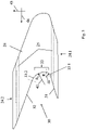
- figure 2 shows a side view of a moving blade 20 of the turbine 1c, specifically of the low-pressure turbine module 1cb.
- This has a rotor blade 23 and a shroud 24 and is mounted on a disk (not shown here) via a blade root 21 .
- Sealing tips 25 are arranged radially on the outside of the shroud 24, which, during operation, for example, run into a run-in coating of the housing (not shown).
- figure 3 shows the shroud 24 in a tangential section, with its axial front end 24.1 in figure 2 left and the axial rear end 24.2 in figure 2 lies on the right.
- the sealing tips 25 are shown, which, however, lie outside the sectional plane and are therefore shown in dashed lines.
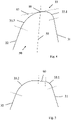
- the subject relates in particular to the profiling of the peripheral side 30 of the shroud 24. This is framed by a free flank 32 and an axially opposite contact flank 31, with an intermediate section 33 formed in between.
- the intermediate section 33 is held in a first transition section 33 .
- the curvatures 41, 42 are implemented via a first and second radius of curvature R 1 , R 2 , the greater curvature corresponding to a smaller radius.
- the combination of lesser and greater curvature can be advantageous with regard to the mechanical stress level in the shroud 24, on the one hand, while on the other hand the extent of the contact flank 31 and thus the contact with the adjacent shroud is at least not significantly reduced, compare the introduction to the description in detail.
- For orientation are in figure 3 an axial direction 45 and a circumferential direction 46 are also shown.
- figure 4 shows the groove 50 formed between the contact flank 31 and the free flank 32 again in a detailed view (likewise in a tangential section). Also shown is a bisecting line 55 lying centrally between the contact flank and the free flank 31, 32, which intersects the intermediate section 33 in a groove base 56. A tangent 57 applied there lies obliquely due to the asymmetrical design, i.e. not at right angles to the bisecting line 55.
- figure 5 shows a slightly modified embodiment, in which the first and second transition sections 33.1, 33.2 do not merge directly into one another. Instead, a middle section 60 is formed in between, which extends in a straight line and runs tangentially into the two transition sections 33.1, 33.2.
Landscapes
- Engineering & Computer Science (AREA)
- Mechanical Engineering (AREA)
- General Engineering & Computer Science (AREA)
- Structures Of Non-Positive Displacement Pumps (AREA)
- Physics & Mathematics (AREA)
- Fluid Mechanics (AREA)
- Turbine Rotor Nozzle Sealing (AREA)
Abstract
Description
- Die vorliegende Erfindung betrifft eine Laufschaufel für eine Strömungsmaschine.
- Bei der Strömungsmaschine kann es sich bspw. um ein Strahltriebwerk handeln, z. B. um ein Mantelstromtriebwerk. Funktional gliedert sich die Strömungsmaschine in Verdichter, Brennkammer und Turbine. Etwa im Falle des Strahltriebwerks wird angesaugte Luft vom Verdichter komprimiert und in der nachgelagerten Brennkammer mit hinzugemischtem Kerosin verbrannt. Das entstehende Heißgas, eine Mischung aus Verbrennungsgas und Luft, durchströmt die nachgelagerte Turbine und wird dabei expandiert. Die Turbine ist in der Regel aus mehreren Stufen mit jeweils einem Stator (Leitschaufelkranz) und einem Rotor (Laufschaufelkranz) aufgebaut, die Rotoren werden von dem Heißgas angetrieben. In jeder Stufe wird dem Heißgas dabei anteilig innere Energie entzogen, die in eine Bewegung des jeweiligen Laufschaufelkranzes und damit der Welle umgesetzt wird.
- Der vorliegende Gegenstand betrifft eine Laufschaufel zum Anordnen im Gaskanal der Strömungsmaschine. Die Laufschaufel kann im Allgemeinen auch im Verdichterbereich Anwendung finden, also im Verdichtergaskanal angeordnet werden; bevorzugt ist eine Anwendung im Turbinenbereich, wird sie also im Heißgaskanal platziert.
- Der vorliegenden Erfindung liegt das technische Problem zugrunde, eine besonders vorteilhafte Laufschaufel anzugeben.
- Dies wird erfindungsgemäß mit der Laufschaufel nach Anspruch 1 gelöst, konkret mit der Gestaltung des Deckbands. Dieses ist an einer Umfangsseite profiliert, hat dort nämlich eine zumindest anteilig axial orientierte, insbesondere geradlinige, Freiflanke und eine dieser gegenüberliegende, insbesondere geradlinige, Kontaktflanke. Ein Zwischenabschnitt, der den Übergang zwischen Frei- und Kontaktflanke markiert, ist dabei in einem Tangentialschnitt betrachtet mit unterschiedlichen Krümmungen gefasst, nämlich in einem ersten Übergangsabschnitt zur Kontaktflanke stärker gekrümmt als in einem zweiten Übergangsabschnitt zur Freiflanke.
- Dieser Krümmungsverlauf bzw. die Kombination aus geringerer Krümmung im Übergang zur Freiflanke und stärkerer Krümmung im Übergang zur Kontaktflanke kann hinsichtlich des mechanischen Spannungsniveaus im Deckband von Vorteil sein und zugleich eine hinreichende Anlage- bzw. Kontaktfläche zum benachbarten Deckband sicherstellen. Betrachtet man zur Illustration allein die mechanischen Spannungen, wäre im Zwischenabschnitt eine möglichst geringe Krümmung von Interesse, also bspw. ein möglichst großer Krümmungsradius. Damit würde aber ein Abstand, den der im Zwischenabschnitt liegende Nutgrund von einem Kreuzungspunkt der Flanken hat, beliebig zunehmen, würde sich also in anderen Worten der Zwischenabschnitt zunehmend in die Flanken hinein verschieben.
- Damit würde insbesondere auch die Länge der Kontaktflanke abnehmen, wäre also die Anlagefläche zum benachbarten Deckband verringert und dementsprechend eine sich aus dem Krafteintrag infolge der Anlage ergebende mechanische Belastung erhöht. Umgekehrt kann mit dem vorliegenden Gegenstand, also der im Verhältnis stärkeren Krümmung im Übergang zur Kontaktflanke, deren Länge erhalten oder zumindest nicht übermäßig verringert werden, obwohl der Übergang in die Freiflanke mit einer geringeren Krümmung, also bspw. einem größeren Radius gefasst ist. Bildlich gesprochen kann aufgrund dieser Krümmungskombination mehr Material am Nutgrund verbleiben.
- Bevorzugte Ausführungsformen finden sich in den abhängigen Ansprüchen und der gesamten Offenbarung, wobei in der Darstellung der Merkmale nicht immer im Einzelnen zwischen Vorrichtungs- und Verfahrens- bzw. Verwendungsaspekten unterschieden wird; jedenfalls implizit ist die Offenbarung hinsichtlich sämtlicher Anspruchskategorien zu lesen. Werden bspw. die Vorteile der Laufschaufel in einer bestimmten Anwendung beschrieben, ist dies als Offenbarung sowohl der entsprechend ausgelegten Laufschaufel als auch einer solchen Verwendung zu lesen.
- Die Angaben "axial", "radial" und "Umlauf" bzw. "umlaufend", sowie die zugehörigen Richtungen (Axialrichtung etc.), beziehen sich ohne ausdrücklich gegenteilige Angabe auf die Drehachse, um welche die Laufschaufel im Betrieb rotiert. Diese fällt typischerweise mit einer Längsachse der Strömungsmaschine zusammen, insbesondere des Triebwerks bzw. Triebwerkmoduls. Der "Tangentialschnitt" wird in einer an den Umlauf tangentialen und dabei achsparallelen Schnittebene genommen, die durch das Deckband und insbesondere dessen Umfangsseite verläuft. Bevorzugt ist die Umfangsseite über ihre gesamte radiale Höhe entsprechend profiliert, ist also das hauptanspruchsgemäße Kriterium in sämtlichen durch die Umfangsseite verlaufenden Tangentialschnitten erfüllt.
- Die "Umfangsseite" des Deckbands weist in Umlaufrichtung, das Deckband grenzt mit der Umfangsseite an das benachbarte Deckband (der benachbarten Laufschaufel). Die Kontaktflanke kann bspw. näher an der axial vorderen Stirnseite des Deckbands angeordnet sein (und umgekehrt die Freiflanke näher an der axial hinteren Stirnseite); bezogen auf eine Durchströmung des Gaskanals kann die Kontaktflanke also stromauf der Freiflanke liegen (und umgekehrt letztere stromab der Kontaktflanke). Die Freiflanke ist "zumindest anteilig axial orientiert", eine Flächennormale auf der Freiflanke hat also zumindest eine Richtungskomponente in axialer Richtung, insbesondere nach axial vorne.
- Bevorzugt liegt die Freiflanke schräg (nicht senkrecht) zur axialen Richtung, die Flächennormale kann mit letzterer bspw. einen Winkel von mindestens 20° oder 25° einschließen, wobei mögliche Obergrenzen bspw. bei höchstens 45°, 40° bzw. 35° liegen können (betrachtet wird hierbei jeweils der kleinere von zwei zwischen Normale und axialer Richtung eingeschlossenen Winkeln). Die Kontaktflanke ist ebenfalls zumindest anteilig axial orientiert, ihre Flächennormale hat also ebenfalls zumindest eine Richtungskomponente in axialer Richtung. Da sie der Freiflanke axial gegenüberliegend angeordnet ist, weist die Flächennormale in die axial entgegengesetzte Richtung, insbesondere nach axial hinten. Auch die Kontaktflanke liegt bevorzugt schräg (nicht senkrecht) zur axialen Richtung, sie kann mit der Freiflanke bspw. einen Schnittwinkel von mindestens 55° oder 60° einschließen, mit möglichen Obergrenzen bei bspw. höchstens 75° oder 70°.
- Generell sind "ein" und "eine" im Rahmen dieser Offenbarung ohne ausdrücklich gegenteilige Angabe als unbestimmte Artikel und damit immer auch als "mindestens ein" bzw. "mindestens eine" zu lesen, es können an dem Deckband also bspw. auch mindestens zwei Schaufelblätter vorgesehen sein ("Mehrfachsegment"). Das erfindungsgemäß profilierte Deckband kann im Allgemeinen auch ein radial innen am Schaufelblatt angeordnetes Innendeckband sein, bevorzugt handelt es sich jedoch um ein Außendeckband (radial außen am Schaufelblatt). Radial außen am Deckband kann eine Dichtspitze, also ein sich in Umlaufrichtung erstreckender Dichtsteg, vorgesehen sein, etwa eine Dichtspitze axial vorne und eine weitere axial hinten.
- Gemäß einer bevorzugten Ausführungsform weist der Zwischenabschnitt einen Mittenabschnitt auf, der zwischen dem stärker gekrümmten ersten Übergangsabschnitt und dem weniger stark gekrümmten zweiten Übergangsabschnitt liegt und sich im Tangentialschnitt betrachtet geradlinig erstreckt. Bevorzugt geht der Mittenabschnitt tangential in den ersten und/oder zweiten Übergangsabschnitt über, können also in anderen Worten die erste und die zweite Krümmung über eine Tangente miteinander verbunden sein. Der Mittenabschnitt kann bspw. eine Designfreiheit bzw. Anpassungsmöglichkeit schaffen, etwa bei der Integration der unterschiedlich starken Krümmungen in ein bestehendes Design.
- Bei einer alternativ bevorzugten Ausführungsform gehen der erste und der zweite Übergangsabschnitt direkt ineinander über, also ohne Geradenstück dazwischen. Der Übergang ist dabei bevorzugt tangential, der erste und zweite Übergangsabschnitt haben dann also im Übergangspunkt eine gemeinsame Tangente.
- In bevorzugter Ausgestaltung hat der erste Übergangsabschnitt einen konstanten ersten Krümmungsradius und/oder hat der zweite Übergangsabschnitt einen konstanten zweiten Krümmungsradius. Bevorzugt gilt beides, wobei der erste Krümmungsradius dann kleiner als der zweite und entsprechend die erste Krümmung stärker als die zweite ist. Alternativ zu einem konstanten Radius bzw. Radien sind im Allgemeinen hingegen beliebige Verläufe denkbar, bspw. elliptisch oder auch frei geformt bzw. mit Splines gefittet. Im Vergleich dazu kann die "Regelkörpergeometrie", also Gestaltung mit Kreisen bzw. Radien und gegebenenfalls einer Geraden, jedoch bspw. leichter zu vermaßen sein, auch Zeichnungen können leichter erstellt bzw. überprüft werden, jedenfalls bei standardmäßigem Vorgehen.
- Gemäß einer bevorzugten Ausführungsform ist der Zwischenabschnitt ausschließlich mit dem ersten und dem zweiten Krümmungsradius gefasst, gibt es also keine anderen Krümmungen. Optional kann das Geraden- bzw. Tangentenstück dazwischen vorgesehen sein, siehe vorne.
- Gemäß einer Ausführungsform weist in einem Tangentialschnitt betrachtet von der, insbesondere geradlinigen, Kontaktflanke zu der, insbesondere geradlinigen, Freiflanke jede Krümmung der Umfangsseite dasselbe Vorzeichen auf, ist insbesondere konkav, und/oder ist in einem Tangentialschnitt betrachtet von der, insbesondere geradlinigen, Kontaktflanke zu der, insbesondere geradlinigen, Freiflanke jeder Übergang von einem gekrümmten in einen geradlinigen Abschnitt tangential.
- Vorzugsweise ist der Verlauf der Umfangsseite in einem Tangentialschnitt betrachtet von der, insbesondere geradlinigen, Kontaktflanke zu der, insbesondere geradlinigen, Freiflanke stetig differenzierbar, weist also keinen Knick, Sprung oder Unstetigkeit auf.
- In bevorzugter Ausgestaltung geht der erste Übergangsabschnitt tangential in die, insbesondere geradlinige, Kontaktflanke über und/oder geht der zweite Übergangsabschnitt tangential in die, insbesondere geradlinige, Freiflanke über. In dem Tangentialschnitt betrachtet kann eine geradlinige Verlängerung der Freiflanke also eine Tangente an einen in den zweiten Übergangsabschnitt gelegten Kreis sein (mit einem zweiten Radius) und/oder kann eine geradlinige Verlängerung der Kontaktflanke eine Tangente an einen in den ersten Übergangsabschnitt gelegten Kreis (mit einem ersten Radius) sein. Der tangentiale Übergang kann bspw. hinsichtlich der mechanischen Spannungen von Vorteil sein.
- In bevorzugter Ausgestaltung ist eine mit dem Zwischenabschnitt gebildete Nut dahingehend asymmetrisch, dass eine Winkelhalbierende schräg zu einer Tangente am Nutgrund liegt. Die Winkelhalbierende liegt mittig zwischen Kontakt- und Freiflanke, und sie schneidet den Zwischenabschnitt per definitionem im Nutgrund. Legt man in diesem Schnittpunkt eine Tangente an den Zwischenabschnitt, liegt diese schräg, also nicht rechtwinklig zur Winkelhalbierenden.
- Bei einer bevorzugten Ausführungsform ist der Zwischenabschnitt von gegebenenfalls dem Geraden- bzw. Tangentenstück abgesehen allenfalls konkav gekrümmt, gibt es also keinen konvex gekrümmten Abschnitt. Insbesondere in Zusammenhang mit dem bzw. den tangentialen Übergängen der Übergangsabschnitte in die Kontakt- und Freiflanke kann die Umfangsseite in dem Bereich "Kontaktflanke-Zwischenabschnitt-Freiflanke" dann insgesamt ohne konvexe Krümmung vorgesehen sein, was bspw. in Leckagehinsicht Vorteile bieten kann. Aufgrund der Gestaltung ohne Krümmungsumkehr bzw. -wechsel oder -unstetigkeit kann z. B. eine komplementäre Gestaltung des angrenzenden Deckbands vereinfacht sein und dementsprechend eine dichtere Anlage erreicht werden.
- Generell ist eine entgegengesetzte Umfangsseite des Deckbands, die der profilierten Umfangsseite in Umlaufrichtung entgegengesetzt liegt, bevorzugt komplementär profiliert. In einem Laufschaufelkranz kann die in Rede stehende Laufschaufel umlaufend mit weiteren Laufschaufeln bzw. Segmenten zusammengesetzt sein, wobei bevorzugt umlaufend baugleiche Deckbänder aneinander gesetzt sind.
- Zusätzlich zu einem Laufschaufelkranz richtet sich der Gegenstand auch auf ein Turbinenmodul, insbesondere ein Turbinenmodul für ein Flugtriebwerk. Bei diesem kann es sich bspw. um ein Geared-Turbo-Fan-Triebwerk handeln, aufgrund der Kopplung über das Getriebe kann das Turbinenmodul im Betrieb insbesondere schneller als der Fan des Flugtriebwerks drehen (es kann also "schnelllaufend" sein). Es kann sich bei dem Turbinenmodul bspw. um ein Hochdruck- oder insbesondere Niederdruckturbinenmodul handeln.
- Im Folgenden wird die Erfindung anhand eines Ausführungsbeispiels näher erläutert, wobei die einzelnen Merkmale im Rahmen der nebengeordneten Ansprüche auch in anderer Kombination erfindungswesentlich sein können und auch weiterhin nicht im Einzelnen zwischen den unterschiedlichen Anspruchskategorien unterschieden wird.
- Im Einzelnen zeigt
- Figur 1
- schematisch ein Mantelstromtriebwerk in einem Axialschnitt;
- Figur 2
- eine Laufschaufel mit Schaufelblatt und Deckband in einer schematischen Seitenansicht;
- Figur 3
- das Deckband der Laufschaufel gemäß
Figur 2 in einem Tangentialschnitt; - Figur 4
- eine Detailansicht zu
Figur 3 ; - Figur 5
- eine zu
Figur 4 alternative Ausgestaltung der Profilierung. -
Figur 1 zeigt eine Strömungsmaschine 1 in schematischer Ansicht, konkret ein Mantelstromtriebwerk. Die Strömungsmaschine 1 gliedert sich funktional in Verdichter 1a, Brennkammer 1b und Turbine 1c, letztere weist ein Hochdruckturbinenmodul 1ca und ein Niederdruckturbinenmodul 1cb auf. Dabei sind sowohl der Verdichter 1a als auch die Turbine 1c jeweils aus mehreren Stufen aufgebaut, jede Stufe setzt sich aus einem Leit- und einem Laufschaufelkranz zusammen. Im Betrieb rotieren die Laufschaufeln um die Längsachse 2. -
Figur 2 zeigt in einer Seitenansicht eine Laufschaufel 20 der Turbine 1c, konkret des Niederdruckturbinenmoduls 1 cb. Diese weist ein Laufschaufelblatt 23 und ein Deckband 24 auf, über einen Schaufelfuß 21 wird sie an eine Scheibe montiert (hier nicht dargestellt). Radial außen an dem Deckband 24 sind Dichtspitzen 25 angeordnet, die im Betrieb bspw. in einen Einlaufbelag des Gehäuses einlaufen (nicht dargestellt). -
Figur 3 zeigt das Deckband 24 in einem Tangentialschnitt, wobei dessen axial vorderes Ende 24.1 inFigur 2 links und das axial hintere Ende 24.2 inFigur 2 rechts liegt. Zur Orientierung sind inFigur 3 ferner die Dichtspitzen 25 dargestellt, die jedoch außerhalb der Schnittebene liegen und deshalb strichliert wiedergegeben sind. Der Gegenstand richtet sich insbesondere auf die Profilierung der Umfangsseite 30 des Deckbands 24. Diese ist mit einer Freiflanke 32 und einer axial gegenüberliegenden Kontaktflanke 31 gefasst, dazwischen ist ein Zwischenabschnitt 33 ausgebildet. - Der Zwischenabschnitt 33 ist in einem ersten Übergangsabschnitt 33.1 der tangential in die Kontaktflanke 31 läuft, mit einer ersten Krümmung 41 gefasst, die größer als eine zweite Krümmung 42 ist, mit welcher ein zweiter Übergangsabschnitt 33.2 in die Freiflanke 32 läuft. Die Krümmungen 41, 42 sind vorliegend über einen ersten und zweiten Krümmungsradius R1, R2 realisiert, wobei die stärkere Krümmung einem kleineren Radius entspricht. Die Kombination aus geringerer und stärkerer Krümmung kann einerseits hinsichtlich des mechanischen Spannungsniveaus im Deckband 24 von Vorteil sein, wobei andererseits die Erstreckung der Kontaktflanke 31 und damit Anlage zum benachbarten Deckband zumindest nicht wesentlich verringert wird, vergleiche die Beschreibungseinleitung im Detail. Zur Orientierung sind in
Figur 3 auch eine Axialrichtung 45 sowie eine Umlaufrichtung 46 gezeigt. -
Figur 4 zeigt die zwischen der Kontaktflanke 31 und der Freiflanke 32 gebildete Nut 50 nochmals in einer Detailansicht (ebenfalls in einem Tangentialschnitt). Dargestellt ist ferner eine mittig zwischen Kontakt- und Freiflanke 31, 32 liegende Winkelhalbierende 55, die den Zwischenabschnitt 33 in einem Nutgrund 56 schneidet. Eine dort angelegte Tangente 57 liegt aufgrund der asymmetrischen Gestaltung schräg, also nicht rechtwinklig zu der Winkelhalbierenden 55. -
Figur 5 zeigt eine leicht abgewandelte Ausführungsform, bei welcher der erste und zweite Übergangsabschnitt 33.1, 33.2 nicht direkt ineinander übergehen. Stattdessen ist dazwischen ein Mittenabschnitt 60 ausgebildet, der sich geradlinig erstreckt und jeweils tangential in die beiden Übergangsabschnitte 33.1, 33.2 läuft. -
Strömungsmaschine 1 Turbine 1c Hochdruckturbinenmodul 1ca Niederdruckturbinenmodul 1cb Längsachse 2 Laufschaufel 20 Schaufelfuß 21 Laufschaufelblatt 23 Deckband 24 Axial vorderes Ende 24.1 Axial hinteres Ende 24.2 Dichtspitzen 25 Umfangsseite 30 Kontaktflanke 31 Freiflanke 32 Zwischenabschnitt 33 Erster Übergangsabschnitt 33.1 Zweiter Übergangsabschnitt 33.2 Erste Krümmung 41 Zweite Krümmung 42 Axialrichtung 45 Umlaufrichtung 46 Nut 50 Winkelhalbierende 55 Nutgrund 56 Tangente 57 Mittenabschnitt 60 Erster Krümmungsradius R1 Zweiter Krümmungsradius R2
Claims (14)
- Laufschaufel (20) für eine Strömungsmaschine (1), mit einem Schaufelblatt (23) und einem Deckband (24),wobei das Deckband (24) an einer Umfangsseite (30) profiliert ist, nämlich in einem Tangentialschnitt betrachtet- eine Kontaktflanke (31) hat, die zumindest anteilig axial orientiert ist, und- eine Freiflanke (32) hat, die ebenfalls zumindest anteilig axial orientiert ist, und zwar der Kontaktflanke (31) entgegengesetzt,wobei in dem Tangentialschnitt betrachtet ein Zwischenabschnitt (33) zwischen der Kontaktflanke (31) und der Freiflanke (32)- in einem ersten Übergangsabschnitt (33.1) zur Kontaktflanke (31) eine erste Krümmung (41) hat und- in einem zweiten Übergangsabschnitt (33.2) zur Freiflanke (32) eine zweite Krümmung (42) hat,wobei die erste Krümmung (41) größer als die zweite Krümmung (42) ist.
- Laufschaufel (20) nach Anspruch 1, bei welcher der Zwischenabschnitt (33) zwischen dem ersten und dem zweiten Übergangsabschnitt (33.1, 33.2) einen Mittenabschnitt (60) aufweist, der in dem Tangentialschnitt betrachtet geradlinig verläuft.
- Laufschaufel (20) nach Anspruch 1, bei welcher in dem Zwischenabschnitt (33) der erste und der zweite Übergangsabschnitt (33.1, 33.2) direkt ineinander übergehen.
- Laufschaufel (20) nach einem der vorstehenden Ansprüche, bei welcher der Zwischenabschnitt (33) in dem Tangentialschnitt betrachtet über den ersten Übergangsabschnitt (33.1) hinweg einen konstanten ersten Krümmungsradius R1 hat.
- Laufschaufel (20) nach einem der vorstehenden Ansprüche, bei welcher der Zwischenabschnitt (33) in dem Tangentialschnitt betrachtet über den zweiten Übergangsabschnitt (33.2) hinweg einen konstanten zweiten Krümmungsradius R2 hat.
- Laufschaufel (20) nach den Ansprüchen 4 und 5, bei welcher der Zwischenabschnitt (33) in dem Tangentialschnitt betrachtet, von einer ggf. abschnittsweise geradlinigen Erstreckung abgesehen, ausschließlich mit dem ersten und dem zweiten Krümmungsradius R1, R2 gefasst ist.
- Laufschaufel (20) nach einem der vorstehenden Ansprüche, bei welcher in einem Tangentialschnitt betrachtet von der, insbesondere geradlinigen, Kontaktflanke (31) zu der, insbesondere geradlinigen, Freiflanke (32) jede Krümmung der Umfangsseite (30) dasselbe Vorzeichen aufweist und/oder jeder Übergang von einem gekrümmten in einen geradlinigen Abschnitt tangential ist.
- Laufschaufel (20) nach einem der vorstehenden Ansprüche, bei welcher der erste Übergangsabschnitt (33.1) in dem Tangentialschnitt betrachtet tangential in die, insbesondere geradlinige, Kontaktflanke (31) übergeht.
- Laufschaufel (20) nach einem der vorstehenden Ansprüche, bei welcher der zweite Übergangsabschnitt (33.2) in dem Tangentialschnitt betrachtet tangential in die, insbesondere geradlinige, Freiflanke (32) übergeht.
- Laufschaufel (20) nach einem der vorstehenden Ansprüche, bei welcher in dem Tangentialschnitt betrachtet eine Winkelhalbierende (55), die mittig zwischen der Kontaktflanke (31) und der Freiflanke (32) liegt und den Zwischenabschnitt (33) in einem Nutgrund (56) schneidet, schräg zu einer in dem Nutgrund (56) an den Zwischenabschnitt (33) gelegten Tangente (57) liegt.
- Laufschaufel (20) nach einem der vorstehenden Ansprüche, bei welcher der Zwischenabschnitt (33) in dem Tangentialschnitt betrachtet, von einer ggf. abschnittsweise geradlinigen Erstreckung abgesehen, ausschließlich konkav gekrümmt ist.
- Laufschaufelkranz mit einer Laufschaufel (20) nach einem der vorstehenden Ansprüche.
- Turbinenmodul (1ca, 1cb) mit einer Laufschaufel (20) nach einem der Ansprüche 1 bis 11 oder einem Laufschaufelkranz nach Anspruch 12.
- Strömungsmaschine (1), insbesondere Strahltriebwerk, mit einem Turbinenmodul (1ca, 1cb) nach Anspruch 13.
Applications Claiming Priority (1)
| Application Number | Priority Date | Filing Date | Title |
|---|---|---|---|
| DE102021118184.4A DE102021118184A1 (de) | 2021-07-14 | 2021-07-14 | Laufschaufel für eine strömungsmaschine |
Publications (2)
| Publication Number | Publication Date |
|---|---|
| EP4123123A1 true EP4123123A1 (de) | 2023-01-25 |
| EP4123123B1 EP4123123B1 (de) | 2024-05-15 |
Family
ID=82547263
Family Applications (1)
| Application Number | Title | Priority Date | Filing Date |
|---|---|---|---|
| EP22182760.3A Active EP4123123B1 (de) | 2021-07-14 | 2022-07-04 | Turbinenschaufel für eine strömungsmaschine |
Country Status (4)
| Country | Link |
|---|---|
| US (1) | US12398647B2 (de) |
| EP (1) | EP4123123B1 (de) |
| DE (1) | DE102021118184A1 (de) |
| ES (1) | ES2983543T3 (de) |
Citations (5)
| Publication number | Priority date | Publication date | Assignee | Title |
|---|---|---|---|---|
| US20050106025A1 (en) * | 2003-09-05 | 2005-05-19 | General Electric Company | Conical tip shroud fillet for a turbine bucket |
| US20160369643A1 (en) * | 2014-03-13 | 2016-12-22 | Mitsubishi Heavy Industries, Ltd. | Shroud, blade member, and rotary machine |
| EP3338938A1 (de) * | 2016-12-22 | 2018-06-27 | General Electric Company | Verfahren zur modifizierung eines deckbandes und schaufel |
| EP3382144A1 (de) * | 2017-03-31 | 2018-10-03 | Doosan Heavy Industries & Construction Co., Ltd. | Schaufelschwingungsdämpfungsstruktur und schaufel und turbomaschine damit |
| WO2021156559A1 (fr) * | 2020-02-07 | 2021-08-12 | Safran Aircraft Engines | Aube de turbomachine d'aeronef |
Family Cites Families (6)
| Publication number | Priority date | Publication date | Assignee | Title |
|---|---|---|---|---|
| US4639997A (en) | 1984-01-23 | 1987-02-03 | Tensiodyne Scientific Corporation | Method of making a device for monitoring fatigue life |
| EP1591625A1 (de) * | 2004-04-30 | 2005-11-02 | ALSTOM Technology Ltd | Deckband für eine Gasturbinenschaufel |
| US7270518B2 (en) * | 2005-05-19 | 2007-09-18 | General Electric Company | Steep angle turbine cover buckets having relief grooves |
| US7887295B2 (en) | 2007-11-08 | 2011-02-15 | General Electric Company | Z-Notch shape for a turbine blade |
| US10513934B2 (en) | 2017-01-19 | 2019-12-24 | General Electric Company | Z-notch shape for a turbine blade tip shroud |
| US10731480B2 (en) | 2017-03-17 | 2020-08-04 | Rolls-Royce Corporation | Varying seal rail fillet for turbine blades |
-
2021
- 2021-07-14 DE DE102021118184.4A patent/DE102021118184A1/de active Pending
-
2022
- 2022-07-04 ES ES22182760T patent/ES2983543T3/es active Active
- 2022-07-04 EP EP22182760.3A patent/EP4123123B1/de active Active
- 2022-07-08 US US17/860,997 patent/US12398647B2/en active Active
Patent Citations (5)
| Publication number | Priority date | Publication date | Assignee | Title |
|---|---|---|---|---|
| US20050106025A1 (en) * | 2003-09-05 | 2005-05-19 | General Electric Company | Conical tip shroud fillet for a turbine bucket |
| US20160369643A1 (en) * | 2014-03-13 | 2016-12-22 | Mitsubishi Heavy Industries, Ltd. | Shroud, blade member, and rotary machine |
| EP3338938A1 (de) * | 2016-12-22 | 2018-06-27 | General Electric Company | Verfahren zur modifizierung eines deckbandes und schaufel |
| EP3382144A1 (de) * | 2017-03-31 | 2018-10-03 | Doosan Heavy Industries & Construction Co., Ltd. | Schaufelschwingungsdämpfungsstruktur und schaufel und turbomaschine damit |
| WO2021156559A1 (fr) * | 2020-02-07 | 2021-08-12 | Safran Aircraft Engines | Aube de turbomachine d'aeronef |
Also Published As
| Publication number | Publication date |
|---|---|
| US12398647B2 (en) | 2025-08-26 |
| ES2983543T3 (es) | 2024-10-23 |
| EP4123123B1 (de) | 2024-05-15 |
| DE102021118184A1 (de) | 2023-01-19 |
| US20230020552A1 (en) | 2023-01-19 |
Similar Documents
| Publication | Publication Date | Title |
|---|---|---|
| EP2478186B1 (de) | Rotor einer Turbomaschine | |
| EP1774179B1 (de) | Verdichterschaufel | |
| EP3536974A1 (de) | Gasturbinenverdichter | |
| EP2647796A1 (de) | Dichtungssystem für eine Strömungsmaschine | |
| EP2410131B1 (de) | Rotor einer Turbomaschine | |
| DE102010037692A1 (de) | Geformte Wabendichtung für eine Turbomaschine | |
| DE60217038T2 (de) | Flanschverbindung zwischen Verdichterwelle und Turbinennarbe | |
| WO2014044363A1 (de) | Lagervorrichtung und abgasturbolader | |
| EP3530880A1 (de) | Leitschaufelblatt mit geneigtem abschnitt, zugehöriges leitschaufelsegment, modul, strömungsmaschine und verfahren zum entwerfen eines moduls | |
| EP3581760B1 (de) | Schaufelblatt für eine thermische strömungsmaschine | |
| EP4123123B1 (de) | Turbinenschaufel für eine strömungsmaschine | |
| WO2021083442A1 (de) | Turbomaschinen-leitschaufelanordnung | |
| EP2665896B1 (de) | Zwischengehäuse einer Gasturbine mit einer aussen liegenden Begrenzungswand welche stromaufwärts einer Stützrippe eine in Umfangrichtung verändernde Kontur aufweist zur Verringerung der Sekundärströmungsverluste | |
| DE112019006421T5 (de) | Rotorschaufel und scheibe eines rotationskörpers | |
| EP3194725A1 (de) | Rotor, axialverdichter, verfahren zur montage | |
| DE102023117910A1 (de) | Modul für eine strömungsmaschine | |
| EP4134523A2 (de) | Schaufelfussaufnahme zum aufnehmen einer laufschaufel | |
| EP4265888A1 (de) | Leit- und laufschaufelkranz für ein mantelstromtriebwerk | |
| DE102019216636A1 (de) | Leitschaufelanordnung für eine strömungsmaschine | |
| DE102004004014A1 (de) | Leitschaufel für eine Turbomaschine | |
| EP1673519A1 (de) | Dichtungsanordnung für eine gasturbine | |
| EP4051878B1 (de) | Laufschaufelanordnung für eine strömungsmaschine | |
| EP4715167A1 (de) | Verbindanordnung für eine strömungsmaschine | |
| CH714391B1 (de) | Turbinenleitapparat. | |
| DE102024104891A1 (de) | Strömungsmaschine mit einem Strömungskanal |
Legal Events
| Date | Code | Title | Description |
|---|---|---|---|
| PUAI | Public reference made under article 153(3) epc to a published international application that has entered the european phase |
Free format text: ORIGINAL CODE: 0009012 |
|
| STAA | Information on the status of an ep patent application or granted ep patent |
Free format text: STATUS: THE APPLICATION HAS BEEN PUBLISHED |
|
| AK | Designated contracting states |
Kind code of ref document: A1 Designated state(s): AL AT BE BG CH CY CZ DE DK EE ES FI FR GB GR HR HU IE IS IT LI LT LU LV MC MK MT NL NO PL PT RO RS SE SI SK SM TR |
|
| STAA | Information on the status of an ep patent application or granted ep patent |
Free format text: STATUS: REQUEST FOR EXAMINATION WAS MADE |
|
| 17P | Request for examination filed |
Effective date: 20230707 |
|
| RBV | Designated contracting states (corrected) |
Designated state(s): AL AT BE BG CH CY CZ DE DK EE ES FI FR GB GR HR HU IE IS IT LI LT LU LV MC MK MT NL NO PL PT RO RS SE SI SK SM TR |
|
| RIC1 | Information provided on ipc code assigned before grant |
Ipc: F01D 5/22 20060101AFI20230930BHEP |
|
| GRAP | Despatch of communication of intention to grant a patent |
Free format text: ORIGINAL CODE: EPIDOSNIGR1 |
|
| STAA | Information on the status of an ep patent application or granted ep patent |
Free format text: STATUS: GRANT OF PATENT IS INTENDED |
|
| INTG | Intention to grant announced |
Effective date: 20231213 |
|
| GRAS | Grant fee paid |
Free format text: ORIGINAL CODE: EPIDOSNIGR3 |
|
| GRAA | (expected) grant |
Free format text: ORIGINAL CODE: 0009210 |
|
| STAA | Information on the status of an ep patent application or granted ep patent |
Free format text: STATUS: THE PATENT HAS BEEN GRANTED |
|
| AK | Designated contracting states |
Kind code of ref document: B1 Designated state(s): AL AT BE BG CH CY CZ DE DK EE ES FI FR GB GR HR HU IE IS IT LI LT LU LV MC MK MT NL NO PL PT RO RS SE SI SK SM TR |
|
| REG | Reference to a national code |
Ref country code: CH Ref legal event code: EP |
|
| REG | Reference to a national code |
Ref country code: IE Ref legal event code: FG4D Free format text: LANGUAGE OF EP DOCUMENT: GERMAN |
|
| REG | Reference to a national code |
Ref country code: DE Ref legal event code: R096 Ref document number: 502022000897 Country of ref document: DE |
|
| REG | Reference to a national code |
Ref country code: LT Ref legal event code: MG9D |
|
| REG | Reference to a national code |
Ref country code: NL Ref legal event code: MP Effective date: 20240515 |
|
| PG25 | Lapsed in a contracting state [announced via postgrant information from national office to epo] |
Ref country code: IS Free format text: LAPSE BECAUSE OF FAILURE TO SUBMIT A TRANSLATION OF THE DESCRIPTION OR TO PAY THE FEE WITHIN THE PRESCRIBED TIME-LIMIT Effective date: 20240915 |
|
| PG25 | Lapsed in a contracting state [announced via postgrant information from national office to epo] |
Ref country code: BG Free format text: LAPSE BECAUSE OF FAILURE TO SUBMIT A TRANSLATION OF THE DESCRIPTION OR TO PAY THE FEE WITHIN THE PRESCRIBED TIME-LIMIT Effective date: 20240515 |
|
| PG25 | Lapsed in a contracting state [announced via postgrant information from national office to epo] |
Ref country code: HR Free format text: LAPSE BECAUSE OF FAILURE TO SUBMIT A TRANSLATION OF THE DESCRIPTION OR TO PAY THE FEE WITHIN THE PRESCRIBED TIME-LIMIT Effective date: 20240515 Ref country code: FI Free format text: LAPSE BECAUSE OF FAILURE TO SUBMIT A TRANSLATION OF THE DESCRIPTION OR TO PAY THE FEE WITHIN THE PRESCRIBED TIME-LIMIT Effective date: 20240515 |
|
| PG25 | Lapsed in a contracting state [announced via postgrant information from national office to epo] |
Ref country code: GR Free format text: LAPSE BECAUSE OF FAILURE TO SUBMIT A TRANSLATION OF THE DESCRIPTION OR TO PAY THE FEE WITHIN THE PRESCRIBED TIME-LIMIT Effective date: 20240816 |
|
| PG25 | Lapsed in a contracting state [announced via postgrant information from national office to epo] |
Ref country code: PT Free format text: LAPSE BECAUSE OF FAILURE TO SUBMIT A TRANSLATION OF THE DESCRIPTION OR TO PAY THE FEE WITHIN THE PRESCRIBED TIME-LIMIT Effective date: 20240916 |
|
| PG25 | Lapsed in a contracting state [announced via postgrant information from national office to epo] |
Ref country code: NL Free format text: LAPSE BECAUSE OF FAILURE TO SUBMIT A TRANSLATION OF THE DESCRIPTION OR TO PAY THE FEE WITHIN THE PRESCRIBED TIME-LIMIT Effective date: 20240515 |
|
| REG | Reference to a national code |
Ref country code: ES Ref legal event code: FG2A Ref document number: 2983543 Country of ref document: ES Kind code of ref document: T3 Effective date: 20241023 |
|
| PG25 | Lapsed in a contracting state [announced via postgrant information from national office to epo] |
Ref country code: PL Free format text: LAPSE BECAUSE OF FAILURE TO SUBMIT A TRANSLATION OF THE DESCRIPTION OR TO PAY THE FEE WITHIN THE PRESCRIBED TIME-LIMIT Effective date: 20240515 |
|
| PG25 | Lapsed in a contracting state [announced via postgrant information from national office to epo] |
Ref country code: LV Free format text: LAPSE BECAUSE OF FAILURE TO SUBMIT A TRANSLATION OF THE DESCRIPTION OR TO PAY THE FEE WITHIN THE PRESCRIBED TIME-LIMIT Effective date: 20240515 |
|
| PG25 | Lapsed in a contracting state [announced via postgrant information from national office to epo] |
Ref country code: PT Free format text: LAPSE BECAUSE OF FAILURE TO SUBMIT A TRANSLATION OF THE DESCRIPTION OR TO PAY THE FEE WITHIN THE PRESCRIBED TIME-LIMIT Effective date: 20240916 Ref country code: PL Free format text: LAPSE BECAUSE OF FAILURE TO SUBMIT A TRANSLATION OF THE DESCRIPTION OR TO PAY THE FEE WITHIN THE PRESCRIBED TIME-LIMIT Effective date: 20240515 Ref country code: NO Free format text: LAPSE BECAUSE OF FAILURE TO SUBMIT A TRANSLATION OF THE DESCRIPTION OR TO PAY THE FEE WITHIN THE PRESCRIBED TIME-LIMIT Effective date: 20240815 Ref country code: NL Free format text: LAPSE BECAUSE OF FAILURE TO SUBMIT A TRANSLATION OF THE DESCRIPTION OR TO PAY THE FEE WITHIN THE PRESCRIBED TIME-LIMIT Effective date: 20240515 Ref country code: LV Free format text: LAPSE BECAUSE OF FAILURE TO SUBMIT A TRANSLATION OF THE DESCRIPTION OR TO PAY THE FEE WITHIN THE PRESCRIBED TIME-LIMIT Effective date: 20240515 Ref country code: IS Free format text: LAPSE BECAUSE OF FAILURE TO SUBMIT A TRANSLATION OF THE DESCRIPTION OR TO PAY THE FEE WITHIN THE PRESCRIBED TIME-LIMIT Effective date: 20240915 Ref country code: HR Free format text: LAPSE BECAUSE OF FAILURE TO SUBMIT A TRANSLATION OF THE DESCRIPTION OR TO PAY THE FEE WITHIN THE PRESCRIBED TIME-LIMIT Effective date: 20240515 Ref country code: GR Free format text: LAPSE BECAUSE OF FAILURE TO SUBMIT A TRANSLATION OF THE DESCRIPTION OR TO PAY THE FEE WITHIN THE PRESCRIBED TIME-LIMIT Effective date: 20240816 Ref country code: FI Free format text: LAPSE BECAUSE OF FAILURE TO SUBMIT A TRANSLATION OF THE DESCRIPTION OR TO PAY THE FEE WITHIN THE PRESCRIBED TIME-LIMIT Effective date: 20240515 Ref country code: BG Free format text: LAPSE BECAUSE OF FAILURE TO SUBMIT A TRANSLATION OF THE DESCRIPTION OR TO PAY THE FEE WITHIN THE PRESCRIBED TIME-LIMIT Effective date: 20240515 Ref country code: RS Free format text: LAPSE BECAUSE OF FAILURE TO SUBMIT A TRANSLATION OF THE DESCRIPTION OR TO PAY THE FEE WITHIN THE PRESCRIBED TIME-LIMIT Effective date: 20240815 |
|
| PG25 | Lapsed in a contracting state [announced via postgrant information from national office to epo] |
Ref country code: DK Free format text: LAPSE BECAUSE OF FAILURE TO SUBMIT A TRANSLATION OF THE DESCRIPTION OR TO PAY THE FEE WITHIN THE PRESCRIBED TIME-LIMIT Effective date: 20240515 |
|
| PG25 | Lapsed in a contracting state [announced via postgrant information from national office to epo] |
Ref country code: EE Free format text: LAPSE BECAUSE OF FAILURE TO SUBMIT A TRANSLATION OF THE DESCRIPTION OR TO PAY THE FEE WITHIN THE PRESCRIBED TIME-LIMIT Effective date: 20240515 |
|
| PG25 | Lapsed in a contracting state [announced via postgrant information from national office to epo] |
Ref country code: CZ Free format text: LAPSE BECAUSE OF FAILURE TO SUBMIT A TRANSLATION OF THE DESCRIPTION OR TO PAY THE FEE WITHIN THE PRESCRIBED TIME-LIMIT Effective date: 20240515 |
|
| PG25 | Lapsed in a contracting state [announced via postgrant information from national office to epo] |
Ref country code: SK Free format text: LAPSE BECAUSE OF FAILURE TO SUBMIT A TRANSLATION OF THE DESCRIPTION OR TO PAY THE FEE WITHIN THE PRESCRIBED TIME-LIMIT Effective date: 20240515 Ref country code: RO Free format text: LAPSE BECAUSE OF FAILURE TO SUBMIT A TRANSLATION OF THE DESCRIPTION OR TO PAY THE FEE WITHIN THE PRESCRIBED TIME-LIMIT Effective date: 20240515 |
|
| PG25 | Lapsed in a contracting state [announced via postgrant information from national office to epo] |
Ref country code: SM Free format text: LAPSE BECAUSE OF FAILURE TO SUBMIT A TRANSLATION OF THE DESCRIPTION OR TO PAY THE FEE WITHIN THE PRESCRIBED TIME-LIMIT Effective date: 20240515 |
|
| PG25 | Lapsed in a contracting state [announced via postgrant information from national office to epo] |
Ref country code: SM Free format text: LAPSE BECAUSE OF FAILURE TO SUBMIT A TRANSLATION OF THE DESCRIPTION OR TO PAY THE FEE WITHIN THE PRESCRIBED TIME-LIMIT Effective date: 20240515 Ref country code: SK Free format text: LAPSE BECAUSE OF FAILURE TO SUBMIT A TRANSLATION OF THE DESCRIPTION OR TO PAY THE FEE WITHIN THE PRESCRIBED TIME-LIMIT Effective date: 20240515 Ref country code: RO Free format text: LAPSE BECAUSE OF FAILURE TO SUBMIT A TRANSLATION OF THE DESCRIPTION OR TO PAY THE FEE WITHIN THE PRESCRIBED TIME-LIMIT Effective date: 20240515 Ref country code: EE Free format text: LAPSE BECAUSE OF FAILURE TO SUBMIT A TRANSLATION OF THE DESCRIPTION OR TO PAY THE FEE WITHIN THE PRESCRIBED TIME-LIMIT Effective date: 20240515 Ref country code: DK Free format text: LAPSE BECAUSE OF FAILURE TO SUBMIT A TRANSLATION OF THE DESCRIPTION OR TO PAY THE FEE WITHIN THE PRESCRIBED TIME-LIMIT Effective date: 20240515 Ref country code: CZ Free format text: LAPSE BECAUSE OF FAILURE TO SUBMIT A TRANSLATION OF THE DESCRIPTION OR TO PAY THE FEE WITHIN THE PRESCRIBED TIME-LIMIT Effective date: 20240515 |
|
| PG25 | Lapsed in a contracting state [announced via postgrant information from national office to epo] |
Ref country code: MC Free format text: LAPSE BECAUSE OF FAILURE TO SUBMIT A TRANSLATION OF THE DESCRIPTION OR TO PAY THE FEE WITHIN THE PRESCRIBED TIME-LIMIT Effective date: 20240515 Ref country code: IT Free format text: LAPSE BECAUSE OF FAILURE TO SUBMIT A TRANSLATION OF THE DESCRIPTION OR TO PAY THE FEE WITHIN THE PRESCRIBED TIME-LIMIT Effective date: 20240515 |
|
| REG | Reference to a national code |
Ref country code: DE Ref legal event code: R097 Ref document number: 502022000897 Country of ref document: DE |
|
| PG25 | Lapsed in a contracting state [announced via postgrant information from national office to epo] |
Ref country code: LU Free format text: LAPSE BECAUSE OF NON-PAYMENT OF DUE FEES Effective date: 20240704 |
|
| PLBE | No opposition filed within time limit |
Free format text: ORIGINAL CODE: 0009261 |
|
| STAA | Information on the status of an ep patent application or granted ep patent |
Free format text: STATUS: NO OPPOSITION FILED WITHIN TIME LIMIT |
|
| PG25 | Lapsed in a contracting state [announced via postgrant information from national office to epo] |
Ref country code: LU Free format text: LAPSE BECAUSE OF NON-PAYMENT OF DUE FEES Effective date: 20240704 |
|
| 26N | No opposition filed |
Effective date: 20250218 |
|
| PG25 | Lapsed in a contracting state [announced via postgrant information from national office to epo] |
Ref country code: SI Free format text: LAPSE BECAUSE OF FAILURE TO SUBMIT A TRANSLATION OF THE DESCRIPTION OR TO PAY THE FEE WITHIN THE PRESCRIBED TIME-LIMIT Effective date: 20240515 Ref country code: BE Free format text: LAPSE BECAUSE OF NON-PAYMENT OF DUE FEES Effective date: 20240731 |
|
| REG | Reference to a national code |
Ref country code: BE Ref legal event code: MM Effective date: 20240731 |
|
| PG25 | Lapsed in a contracting state [announced via postgrant information from national office to epo] |
Ref country code: IE Free format text: LAPSE BECAUSE OF NON-PAYMENT OF DUE FEES Effective date: 20240704 |
|
| PG25 | Lapsed in a contracting state [announced via postgrant information from national office to epo] |
Ref country code: SE Free format text: LAPSE BECAUSE OF FAILURE TO SUBMIT A TRANSLATION OF THE DESCRIPTION OR TO PAY THE FEE WITHIN THE PRESCRIBED TIME-LIMIT Effective date: 20240515 |
|
| PGFP | Annual fee paid to national office [announced via postgrant information from national office to epo] |
Ref country code: ES Payment date: 20250819 Year of fee payment: 4 |
|
| PGFP | Annual fee paid to national office [announced via postgrant information from national office to epo] |
Ref country code: DE Payment date: 20250722 Year of fee payment: 4 |
|
| PGFP | Annual fee paid to national office [announced via postgrant information from national office to epo] |
Ref country code: FR Payment date: 20250723 Year of fee payment: 4 Ref country code: AT Payment date: 20251020 Year of fee payment: 4 |
|
| PG25 | Lapsed in a contracting state [announced via postgrant information from national office to epo] |
Ref country code: CY Free format text: LAPSE BECAUSE OF FAILURE TO SUBMIT A TRANSLATION OF THE DESCRIPTION OR TO PAY THE FEE WITHIN THE PRESCRIBED TIME-LIMIT; INVALID AB INITIO Effective date: 20220704 |
|
| REG | Reference to a national code |
Ref country code: CH Ref legal event code: H13 Free format text: ST27 STATUS EVENT CODE: U-0-0-H10-H13 (AS PROVIDED BY THE NATIONAL OFFICE) Effective date: 20260224 |
|
| PG25 | Lapsed in a contracting state [announced via postgrant information from national office to epo] |
Ref country code: HU Free format text: LAPSE BECAUSE OF FAILURE TO SUBMIT A TRANSLATION OF THE DESCRIPTION OR TO PAY THE FEE WITHIN THE PRESCRIBED TIME-LIMIT; INVALID AB INITIO Effective date: 20220704 |
|
| PG25 | Lapsed in a contracting state [announced via postgrant information from national office to epo] |
Ref country code: CH Free format text: LAPSE BECAUSE OF NON-PAYMENT OF DUE FEES Effective date: 20250731 |