EP4123123A1 - Aube motrice pour une turbomachine - Google Patents
Aube motrice pour une turbomachine Download PDFInfo
- Publication number
- EP4123123A1 EP4123123A1 EP22182760.3A EP22182760A EP4123123A1 EP 4123123 A1 EP4123123 A1 EP 4123123A1 EP 22182760 A EP22182760 A EP 22182760A EP 4123123 A1 EP4123123 A1 EP 4123123A1
- Authority
- EP
- European Patent Office
- Prior art keywords
- section
- flank
- curvature
- viewed
- tangential
- Prior art date
- Legal status (The legal status is an assumption and is not a legal conclusion. Google has not performed a legal analysis and makes no representation as to the accuracy of the status listed.)
- Granted
Links
Images


Classifications
-
- F—MECHANICAL ENGINEERING; LIGHTING; HEATING; WEAPONS; BLASTING
- F01—MACHINES OR ENGINES IN GENERAL; ENGINE PLANTS IN GENERAL; STEAM ENGINES
- F01D—NON-POSITIVE DISPLACEMENT MACHINES OR ENGINES, e.g. STEAM TURBINES
- F01D5/00—Blades; Blade-carrying members; Heating, heat-insulating, cooling or antivibration means on the blades or the members
- F01D5/12—Blades
- F01D5/22—Blade-to-blade connections, e.g. for damping vibrations
- F01D5/225—Blade-to-blade connections, e.g. for damping vibrations by shrouding
-
- F—MECHANICAL ENGINEERING; LIGHTING; HEATING; WEAPONS; BLASTING
- F04—POSITIVE - DISPLACEMENT MACHINES FOR LIQUIDS; PUMPS FOR LIQUIDS OR ELASTIC FLUIDS
- F04D—NON-POSITIVE-DISPLACEMENT PUMPS
- F04D19/00—Axial-flow pumps
- F04D19/02—Multi-stage pumps
-
- F—MECHANICAL ENGINEERING; LIGHTING; HEATING; WEAPONS; BLASTING
- F04—POSITIVE - DISPLACEMENT MACHINES FOR LIQUIDS; PUMPS FOR LIQUIDS OR ELASTIC FLUIDS
- F04D—NON-POSITIVE-DISPLACEMENT PUMPS
- F04D29/00—Details, component parts, or accessories
- F04D29/26—Rotors specially for elastic fluids
- F04D29/32—Rotors specially for elastic fluids for axial flow pumps
- F04D29/321—Rotors specially for elastic fluids for axial flow pumps for axial flow compressors
- F04D29/324—Blades
-
- F—MECHANICAL ENGINEERING; LIGHTING; HEATING; WEAPONS; BLASTING
- F05—INDEXING SCHEMES RELATING TO ENGINES OR PUMPS IN VARIOUS SUBCLASSES OF CLASSES F01-F04
- F05D—INDEXING SCHEME FOR ASPECTS RELATING TO NON-POSITIVE-DISPLACEMENT MACHINES OR ENGINES, GAS-TURBINES OR JET-PROPULSION PLANTS
- F05D2250/00—Geometry
- F05D2250/70—Shape
-
- Y—GENERAL TAGGING OF NEW TECHNOLOGICAL DEVELOPMENTS; GENERAL TAGGING OF CROSS-SECTIONAL TECHNOLOGIES SPANNING OVER SEVERAL SECTIONS OF THE IPC; TECHNICAL SUBJECTS COVERED BY FORMER USPC CROSS-REFERENCE ART COLLECTIONS [XRACs] AND DIGESTS
- Y02—TECHNOLOGIES OR APPLICATIONS FOR MITIGATION OR ADAPTATION AGAINST CLIMATE CHANGE
- Y02T—CLIMATE CHANGE MITIGATION TECHNOLOGIES RELATED TO TRANSPORTATION
- Y02T50/00—Aeronautics or air transport
- Y02T50/60—Efficient propulsion technologies, e.g. for aircraft
Definitions
- the present invention relates to a rotor blade for a turbomachine.
- the turbomachine can, for example, be a jet engine, e.g. B. a turbofan engine. Functionally, the turbomachine is divided into compressor, combustion chamber and turbine. In the case of the jet engine, for example, the air drawn in is compressed by the compressor and burned in the downstream combustion chamber with added kerosene. The resulting hot gas, a mixture of combustion gas and air, flows through the downstream turbine and is expanded in the process.
- the turbine is usually made up of several stages, each with a stator (guide blade ring) and a rotor (rotor blade ring), the rotors are driven by the hot gas. In each stage, a proportion of the internal energy is withdrawn from the hot gas, which is converted into a movement of the respective rotor blade ring and thus the shaft.
- the present subject matter relates to a rotor blade to be arranged in the gas duct of the turbomachine.
- the moving blade can also be used in the compressor area, ie it can be arranged in the compressor gas duct; an application in the turbine area is preferred, i.e. it is placed in the hot gas duct.
- the present invention is based on the technical problem of specifying a particularly advantageous moving blade.
- this is achieved with the moving blade according to claim 1, specifically with the design of the shroud.
- This is profiled on one peripheral side, namely there has an at least partially axially oriented, in particular rectilinear, free flank and an opposite, in particular rectilinear, contact flank.
- An intermediate section which marks the transition between the free flank and the contact flank, is viewed in a tangential section with different curvatures, namely more strongly curved in a first transitional section to the contact flank than in a second transitional section to the free flank.
- the length of the contact flank would also decrease, ie the contact surface to the adjacent shroud would be reduced and a mechanical load resulting from the application of force as a result of the contact would be increased accordingly.
- the present object i.e. the relatively greater curvature in the transition to the contact flank
- its length can be maintained or at least not excessively reduced, although the transition to the free flank has a smaller curvature, e.g. a larger radius.
- more material can remain at the bottom of the groove due to this combination of curvatures.
- axial, radial and “circulation” or “circular” and the associated directions refer to the axis of rotation about which the moving blade rotates during operation, unless expressly stated otherwise. This typically coincides with a longitudinal axis of the turbomachine, in particular of the engine or engine module.
- the "tangential section” is taken in a section plane which is tangential to the circumference and parallel to the axis and runs through the shroud and in particular its peripheral side.
- the peripheral side is preferably correspondingly profiled over its entire radial height, ie the main claim criterion is met in all tangential sections running through the peripheral side.
- the "circumferential side" of the shroud faces circumferentially, the shroud circumferentially abuts the adjacent shroud (adjacent blade).
- the contact flank can, for example, be arranged closer to the axially front face of the shroud (and conversely the clearance flank closer to the axially rear face); In relation to a flow through the gas channel, the contact flank can therefore lie upstream of the free flank (and vice versa, the latter downstream of the contact flank).
- the free flank is “oriented axially at least in part”, so a surface normal on the free flank has at least one directional component in the axial direction, in particular towards the front axially.
- the free flank is preferably at an angle (not perpendicular) to the axial direction; the surface normal can, for example, form an angle of at least 20° or 25° with the latter , whereby possible upper limits can be, for example, at most 45°, 40° or 35° (the smaller of two angles enclosed between the normal and the axial direction is considered here in each case).
- the contact flank is also at least partially oriented axially, so its surface normal also has at least one directional component in the axial direction. Since it is arranged axially opposite the free flank, the surface normal points in the axially opposite direction, in particular axially to the rear.
- the contact flank is also preferably inclined (not perpendicular) to the axial direction; it can, for example, enclose an intersection angle of at least 55° or 60° with the free flank, with possible upper limits of, for example, at most 75° or 70°.
- the shroud profiled according to the invention can generally also be an inner shroud arranged radially on the inside of the airfoil, but it is preferably an outer shroud (radially on the outside of the airfoil).
- a sealing tip ie a sealing web extending in the circumferential direction, can be provided radially on the outside of the shroud, for example one sealing tip axially at the front and another axially at the rear.
- the intermediate section has a central section which lies between the more strongly curved first transition section and the less strongly curved second transition section and extends in a straight line when viewed in tangential section.
- the middle section preferably transitions tangentially into the first and/or second transition section, that is to say in other words the first and second curves can be connected to one another via a tangent.
- the middle section can, for example, create design freedom or customization options, for example when integrating the differently strong curvatures into an existing design.
- first and the second transition section merge directly into one another, ie without a straight section in between.
- the transition is preferably tangential, so the first and second transition sections then have a common tangent at the transition point.
- the first transition section has a constant first radius of curvature and/or the second transition section has a constant second radius of curvature. Both preferably apply, the first radius of curvature then being smaller than the second and correspondingly the first curvature being stronger than the second.
- a constant radius or radii any courses are generally conceivable, for example elliptical or also freely formed or fitted with splines.
- the "rule geometry" ie design with circles or radii and possibly a straight line, can be easier to measure, for example, and drawings can also be created or checked more easily, at least with the standard procedure.
- the intermediate section is only set with the first and the second radius of curvature, ie there are no other curvatures.
- the straight line or tangent piece can be provided in between, see above.
- each curvature of the peripheral side has the same sign, is in particular concave, and/or is viewed in a tangential section from the, in particular, straight, contact flank to the free flank, in particular a straight one, each transition from a curved section to a straight section is tangential.
- the course of the peripheral side is preferably viewed in a tangential section from the, in particular straight, contact flank to the, in particular straight, Free edge continuously differentiable, i.e. has no kink, jump or discontinuity.
- the first transition section merges tangentially into the, in particular straight, contact flank and/or the second transition section merges tangentially into the, in particular straight, free flank.
- a straight-line extension of the free flank can be a tangent to a circle placed in the second transition section (with a second radius) and/or a straight-line extension of the contact flank can be a tangent to a circle placed in the first transition section (with a first radius).
- the tangential transition can be advantageous with regard to mechanical stresses, for example.
- a groove formed with the intermediate section is asymmetrical in that an angle bisector lies obliquely to a tangent at the bottom of the groove.
- the bisecting line lies in the middle between the contact flank and the clearance flank, and by definition it intersects the intermediate section at the bottom of the groove. If you put a tangent to the intermediate section at this point of intersection, it will be at an angle, i.e. not at right angles to the bisecting line.
- the intermediate section apart from the straight line or tangent section, is at most concavely curved, ie there is no convexly curved section.
- the circumferential side in the “contact flank-intermediate section-free flank” area can then be provided without any convex curvature overall, which can offer advantages with regard to leakage, for example. Due to the design without curvature reversal or change or discontinuity z. B. a complementary design of the adjacent shroud can be simplified and accordingly a tighter system can be achieved.
- an opposite peripheral side of the shroud which lies opposite the profiled peripheral side in the circumferential direction, is preferably profiled in a complementary manner.
- the rotor blade in question can be assembled circumferentially with further rotor blades or segments, with shrouds of the same construction preferably being placed together circumferentially.
- the subject matter also relates to a turbine module, in particular a turbine module for an aircraft engine.
- a turbine module for an aircraft engine.
- This can, for example, be a geared turbo fan engine, due to the coupling via the gearbox, the turbine module can rotate faster than the fan of the aircraft engine during operation (it can therefore be "high-speed").
- the turbine module can be, for example, a high-pressure or, in particular, a low-pressure turbine module.
- FIG. 1 shows a turbomachine 1 in a schematic view, specifically a turbofan engine.
- the turbomachine 1 is divided functionally into a compressor 1a, a combustion chamber 1b and a turbine 1c, the latter having a high-pressure turbine module 1ca and a low-pressure turbine module 1cb.
- Both the compressor 1a and the turbine 1c are each made up of several stages, each stage is composed of a guide blade ring and a moving blade ring.
- the rotor blades rotate around the longitudinal axis 2.
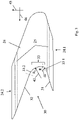
- figure 2 shows a side view of a moving blade 20 of the turbine 1c, specifically of the low-pressure turbine module 1cb.
- This has a rotor blade 23 and a shroud 24 and is mounted on a disk (not shown here) via a blade root 21 .
- Sealing tips 25 are arranged radially on the outside of the shroud 24, which, during operation, for example, run into a run-in coating of the housing (not shown).
- figure 3 shows the shroud 24 in a tangential section, with its axial front end 24.1 in figure 2 left and the axial rear end 24.2 in figure 2 lies on the right.
- the sealing tips 25 are shown, which, however, lie outside the sectional plane and are therefore shown in dashed lines.
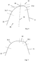
- the subject relates in particular to the profiling of the peripheral side 30 of the shroud 24. This is framed by a free flank 32 and an axially opposite contact flank 31, with an intermediate section 33 formed in between.
- the intermediate section 33 is held in a first transition section 33 .
- the curvatures 41, 42 are implemented via a first and second radius of curvature R 1 , R 2 , the greater curvature corresponding to a smaller radius.
- the combination of lesser and greater curvature can be advantageous with regard to the mechanical stress level in the shroud 24, on the one hand, while on the other hand the extent of the contact flank 31 and thus the contact with the adjacent shroud is at least not significantly reduced, compare the introduction to the description in detail.
- For orientation are in figure 3 an axial direction 45 and a circumferential direction 46 are also shown.
- figure 4 shows the groove 50 formed between the contact flank 31 and the free flank 32 again in a detailed view (likewise in a tangential section). Also shown is a bisecting line 55 lying centrally between the contact flank and the free flank 31, 32, which intersects the intermediate section 33 in a groove base 56. A tangent 57 applied there lies obliquely due to the asymmetrical design, i.e. not at right angles to the bisecting line 55.
- figure 5 shows a slightly modified embodiment, in which the first and second transition sections 33.1, 33.2 do not merge directly into one another. Instead, a middle section 60 is formed in between, which extends in a straight line and runs tangentially into the two transition sections 33.1, 33.2.
Landscapes
- Engineering & Computer Science (AREA)
- Mechanical Engineering (AREA)
- General Engineering & Computer Science (AREA)
- Structures Of Non-Positive Displacement Pumps (AREA)
- Physics & Mathematics (AREA)
- Fluid Mechanics (AREA)
- Turbine Rotor Nozzle Sealing (AREA)
Applications Claiming Priority (1)
| Application Number | Priority Date | Filing Date | Title |
|---|---|---|---|
| DE102021118184.4A DE102021118184A1 (de) | 2021-07-14 | 2021-07-14 | Laufschaufel für eine strömungsmaschine |
Publications (2)
| Publication Number | Publication Date |
|---|---|
| EP4123123A1 true EP4123123A1 (fr) | 2023-01-25 |
| EP4123123B1 EP4123123B1 (fr) | 2024-05-15 |
Family
ID=82547263
Family Applications (1)
| Application Number | Title | Priority Date | Filing Date |
|---|---|---|---|
| EP22182760.3A Active EP4123123B1 (fr) | 2021-07-14 | 2022-07-04 | Aube de turbine pour un moteur à flux |
Country Status (4)
| Country | Link |
|---|---|
| US (1) | US12398647B2 (fr) |
| EP (1) | EP4123123B1 (fr) |
| DE (1) | DE102021118184A1 (fr) |
| ES (1) | ES2983543T3 (fr) |
Citations (5)
| Publication number | Priority date | Publication date | Assignee | Title |
|---|---|---|---|---|
| US20050106025A1 (en) * | 2003-09-05 | 2005-05-19 | General Electric Company | Conical tip shroud fillet for a turbine bucket |
| US20160369643A1 (en) * | 2014-03-13 | 2016-12-22 | Mitsubishi Heavy Industries, Ltd. | Shroud, blade member, and rotary machine |
| EP3338938A1 (fr) * | 2016-12-22 | 2018-06-27 | General Electric Company | Procédé pour modifier une enveloppe et aube |
| EP3382144A1 (fr) * | 2017-03-31 | 2018-10-03 | Doosan Heavy Industries & Construction Co., Ltd. | Structure d'amortissement de vibrations d'ailettes, ailette et turbomachine les comportant |
| WO2021156559A1 (fr) * | 2020-02-07 | 2021-08-12 | Safran Aircraft Engines | Aube de turbomachine d'aeronef |
Family Cites Families (6)
| Publication number | Priority date | Publication date | Assignee | Title |
|---|---|---|---|---|
| US4639997A (en) | 1984-01-23 | 1987-02-03 | Tensiodyne Scientific Corporation | Method of making a device for monitoring fatigue life |
| EP1591625A1 (fr) * | 2004-04-30 | 2005-11-02 | ALSTOM Technology Ltd | Virole pour aube de turbine à gaz |
| US7270518B2 (en) * | 2005-05-19 | 2007-09-18 | General Electric Company | Steep angle turbine cover buckets having relief grooves |
| US7887295B2 (en) | 2007-11-08 | 2011-02-15 | General Electric Company | Z-Notch shape for a turbine blade |
| US10513934B2 (en) | 2017-01-19 | 2019-12-24 | General Electric Company | Z-notch shape for a turbine blade tip shroud |
| US10731480B2 (en) | 2017-03-17 | 2020-08-04 | Rolls-Royce Corporation | Varying seal rail fillet for turbine blades |
-
2021
- 2021-07-14 DE DE102021118184.4A patent/DE102021118184A1/de active Pending
-
2022
- 2022-07-04 ES ES22182760T patent/ES2983543T3/es active Active
- 2022-07-04 EP EP22182760.3A patent/EP4123123B1/fr active Active
- 2022-07-08 US US17/860,997 patent/US12398647B2/en active Active
Patent Citations (5)
| Publication number | Priority date | Publication date | Assignee | Title |
|---|---|---|---|---|
| US20050106025A1 (en) * | 2003-09-05 | 2005-05-19 | General Electric Company | Conical tip shroud fillet for a turbine bucket |
| US20160369643A1 (en) * | 2014-03-13 | 2016-12-22 | Mitsubishi Heavy Industries, Ltd. | Shroud, blade member, and rotary machine |
| EP3338938A1 (fr) * | 2016-12-22 | 2018-06-27 | General Electric Company | Procédé pour modifier une enveloppe et aube |
| EP3382144A1 (fr) * | 2017-03-31 | 2018-10-03 | Doosan Heavy Industries & Construction Co., Ltd. | Structure d'amortissement de vibrations d'ailettes, ailette et turbomachine les comportant |
| WO2021156559A1 (fr) * | 2020-02-07 | 2021-08-12 | Safran Aircraft Engines | Aube de turbomachine d'aeronef |
Also Published As
| Publication number | Publication date |
|---|---|
| US12398647B2 (en) | 2025-08-26 |
| ES2983543T3 (es) | 2024-10-23 |
| EP4123123B1 (fr) | 2024-05-15 |
| DE102021118184A1 (de) | 2023-01-19 |
| US20230020552A1 (en) | 2023-01-19 |
Similar Documents
| Publication | Publication Date | Title |
|---|---|---|
| EP2478186B1 (fr) | Rotor de turbomachine | |
| EP1774179B1 (fr) | Aube de compresseur | |
| EP3536974A1 (fr) | Compresseur de turbine à gaz | |
| EP2647796A1 (fr) | Système d'étanchéité pour turbomachine | |
| EP2410131B1 (fr) | Rotor d'une turbomachine | |
| DE102010037692A1 (de) | Geformte Wabendichtung für eine Turbomaschine | |
| DE60217038T2 (de) | Flanschverbindung zwischen Verdichterwelle und Turbinennarbe | |
| WO2014044363A1 (fr) | Dispositif formant palier ainsi que turbocompresseur | |
| EP3530880A1 (fr) | Pale d'aube directrice avec section inclinée, segment d'aubes directrices, module, turbomachine et procédé de conception d'un module associés | |
| EP3581760B1 (fr) | Pale d'aube pour une turbomachine | |
| EP4123123B1 (fr) | Aube de turbine pour un moteur à flux | |
| WO2021083442A1 (fr) | Ensemble aube directrice de turbomachine | |
| EP2665896B1 (fr) | Carter intermédiaire d'une turbine à gaz comprenant une paroi de limite extérieure en amont d'une entretoise avec un contour variable en direction circonférentielle pour minimiser les pertes de flux secondaires | |
| DE112019006421T5 (de) | Rotorschaufel und scheibe eines rotationskörpers | |
| EP3194725A1 (fr) | Rotor, compresseur axial, procédé de montage | |
| DE102023117910A1 (de) | Modul für eine strömungsmaschine | |
| EP4134523A2 (fr) | Logement de pied d'aube permettant de loger une aube mobile | |
| EP4265888A1 (fr) | Couronne d'aubes directrices et rotoriques pour un moteur à double flux | |
| DE102019216636A1 (de) | Leitschaufelanordnung für eine strömungsmaschine | |
| DE102004004014A1 (de) | Leitschaufel für eine Turbomaschine | |
| EP1673519A1 (fr) | Dispositif d'etancheite con u pour une turbine a gaz | |
| EP4051878B1 (fr) | Agencement d'aube rotative pour une turbomachine | |
| EP4715167A1 (fr) | Ensemble de connexion pour une turbomachine | |
| CH714391B1 (de) | Turbinenleitapparat. | |
| DE102024104891A1 (de) | Strömungsmaschine mit einem Strömungskanal |
Legal Events
| Date | Code | Title | Description |
|---|---|---|---|
| PUAI | Public reference made under article 153(3) epc to a published international application that has entered the european phase |
Free format text: ORIGINAL CODE: 0009012 |
|
| STAA | Information on the status of an ep patent application or granted ep patent |
Free format text: STATUS: THE APPLICATION HAS BEEN PUBLISHED |
|
| AK | Designated contracting states |
Kind code of ref document: A1 Designated state(s): AL AT BE BG CH CY CZ DE DK EE ES FI FR GB GR HR HU IE IS IT LI LT LU LV MC MK MT NL NO PL PT RO RS SE SI SK SM TR |
|
| STAA | Information on the status of an ep patent application or granted ep patent |
Free format text: STATUS: REQUEST FOR EXAMINATION WAS MADE |
|
| 17P | Request for examination filed |
Effective date: 20230707 |
|
| RBV | Designated contracting states (corrected) |
Designated state(s): AL AT BE BG CH CY CZ DE DK EE ES FI FR GB GR HR HU IE IS IT LI LT LU LV MC MK MT NL NO PL PT RO RS SE SI SK SM TR |
|
| RIC1 | Information provided on ipc code assigned before grant |
Ipc: F01D 5/22 20060101AFI20230930BHEP |
|
| GRAP | Despatch of communication of intention to grant a patent |
Free format text: ORIGINAL CODE: EPIDOSNIGR1 |
|
| STAA | Information on the status of an ep patent application or granted ep patent |
Free format text: STATUS: GRANT OF PATENT IS INTENDED |
|
| INTG | Intention to grant announced |
Effective date: 20231213 |
|
| GRAS | Grant fee paid |
Free format text: ORIGINAL CODE: EPIDOSNIGR3 |
|
| GRAA | (expected) grant |
Free format text: ORIGINAL CODE: 0009210 |
|
| STAA | Information on the status of an ep patent application or granted ep patent |
Free format text: STATUS: THE PATENT HAS BEEN GRANTED |
|
| AK | Designated contracting states |
Kind code of ref document: B1 Designated state(s): AL AT BE BG CH CY CZ DE DK EE ES FI FR GB GR HR HU IE IS IT LI LT LU LV MC MK MT NL NO PL PT RO RS SE SI SK SM TR |
|
| REG | Reference to a national code |
Ref country code: CH Ref legal event code: EP |
|
| REG | Reference to a national code |
Ref country code: IE Ref legal event code: FG4D Free format text: LANGUAGE OF EP DOCUMENT: GERMAN |
|
| REG | Reference to a national code |
Ref country code: DE Ref legal event code: R096 Ref document number: 502022000897 Country of ref document: DE |
|
| REG | Reference to a national code |
Ref country code: LT Ref legal event code: MG9D |
|
| REG | Reference to a national code |
Ref country code: NL Ref legal event code: MP Effective date: 20240515 |
|
| PG25 | Lapsed in a contracting state [announced via postgrant information from national office to epo] |
Ref country code: IS Free format text: LAPSE BECAUSE OF FAILURE TO SUBMIT A TRANSLATION OF THE DESCRIPTION OR TO PAY THE FEE WITHIN THE PRESCRIBED TIME-LIMIT Effective date: 20240915 |
|
| PG25 | Lapsed in a contracting state [announced via postgrant information from national office to epo] |
Ref country code: BG Free format text: LAPSE BECAUSE OF FAILURE TO SUBMIT A TRANSLATION OF THE DESCRIPTION OR TO PAY THE FEE WITHIN THE PRESCRIBED TIME-LIMIT Effective date: 20240515 |
|
| PG25 | Lapsed in a contracting state [announced via postgrant information from national office to epo] |
Ref country code: HR Free format text: LAPSE BECAUSE OF FAILURE TO SUBMIT A TRANSLATION OF THE DESCRIPTION OR TO PAY THE FEE WITHIN THE PRESCRIBED TIME-LIMIT Effective date: 20240515 Ref country code: FI Free format text: LAPSE BECAUSE OF FAILURE TO SUBMIT A TRANSLATION OF THE DESCRIPTION OR TO PAY THE FEE WITHIN THE PRESCRIBED TIME-LIMIT Effective date: 20240515 |
|
| PG25 | Lapsed in a contracting state [announced via postgrant information from national office to epo] |
Ref country code: GR Free format text: LAPSE BECAUSE OF FAILURE TO SUBMIT A TRANSLATION OF THE DESCRIPTION OR TO PAY THE FEE WITHIN THE PRESCRIBED TIME-LIMIT Effective date: 20240816 |
|
| PG25 | Lapsed in a contracting state [announced via postgrant information from national office to epo] |
Ref country code: PT Free format text: LAPSE BECAUSE OF FAILURE TO SUBMIT A TRANSLATION OF THE DESCRIPTION OR TO PAY THE FEE WITHIN THE PRESCRIBED TIME-LIMIT Effective date: 20240916 |
|
| PG25 | Lapsed in a contracting state [announced via postgrant information from national office to epo] |
Ref country code: NL Free format text: LAPSE BECAUSE OF FAILURE TO SUBMIT A TRANSLATION OF THE DESCRIPTION OR TO PAY THE FEE WITHIN THE PRESCRIBED TIME-LIMIT Effective date: 20240515 |
|
| REG | Reference to a national code |
Ref country code: ES Ref legal event code: FG2A Ref document number: 2983543 Country of ref document: ES Kind code of ref document: T3 Effective date: 20241023 |
|
| PG25 | Lapsed in a contracting state [announced via postgrant information from national office to epo] |
Ref country code: PL Free format text: LAPSE BECAUSE OF FAILURE TO SUBMIT A TRANSLATION OF THE DESCRIPTION OR TO PAY THE FEE WITHIN THE PRESCRIBED TIME-LIMIT Effective date: 20240515 |
|
| PG25 | Lapsed in a contracting state [announced via postgrant information from national office to epo] |
Ref country code: LV Free format text: LAPSE BECAUSE OF FAILURE TO SUBMIT A TRANSLATION OF THE DESCRIPTION OR TO PAY THE FEE WITHIN THE PRESCRIBED TIME-LIMIT Effective date: 20240515 |
|
| PG25 | Lapsed in a contracting state [announced via postgrant information from national office to epo] |
Ref country code: PT Free format text: LAPSE BECAUSE OF FAILURE TO SUBMIT A TRANSLATION OF THE DESCRIPTION OR TO PAY THE FEE WITHIN THE PRESCRIBED TIME-LIMIT Effective date: 20240916 Ref country code: PL Free format text: LAPSE BECAUSE OF FAILURE TO SUBMIT A TRANSLATION OF THE DESCRIPTION OR TO PAY THE FEE WITHIN THE PRESCRIBED TIME-LIMIT Effective date: 20240515 Ref country code: NO Free format text: LAPSE BECAUSE OF FAILURE TO SUBMIT A TRANSLATION OF THE DESCRIPTION OR TO PAY THE FEE WITHIN THE PRESCRIBED TIME-LIMIT Effective date: 20240815 Ref country code: NL Free format text: LAPSE BECAUSE OF FAILURE TO SUBMIT A TRANSLATION OF THE DESCRIPTION OR TO PAY THE FEE WITHIN THE PRESCRIBED TIME-LIMIT Effective date: 20240515 Ref country code: LV Free format text: LAPSE BECAUSE OF FAILURE TO SUBMIT A TRANSLATION OF THE DESCRIPTION OR TO PAY THE FEE WITHIN THE PRESCRIBED TIME-LIMIT Effective date: 20240515 Ref country code: IS Free format text: LAPSE BECAUSE OF FAILURE TO SUBMIT A TRANSLATION OF THE DESCRIPTION OR TO PAY THE FEE WITHIN THE PRESCRIBED TIME-LIMIT Effective date: 20240915 Ref country code: HR Free format text: LAPSE BECAUSE OF FAILURE TO SUBMIT A TRANSLATION OF THE DESCRIPTION OR TO PAY THE FEE WITHIN THE PRESCRIBED TIME-LIMIT Effective date: 20240515 Ref country code: GR Free format text: LAPSE BECAUSE OF FAILURE TO SUBMIT A TRANSLATION OF THE DESCRIPTION OR TO PAY THE FEE WITHIN THE PRESCRIBED TIME-LIMIT Effective date: 20240816 Ref country code: FI Free format text: LAPSE BECAUSE OF FAILURE TO SUBMIT A TRANSLATION OF THE DESCRIPTION OR TO PAY THE FEE WITHIN THE PRESCRIBED TIME-LIMIT Effective date: 20240515 Ref country code: BG Free format text: LAPSE BECAUSE OF FAILURE TO SUBMIT A TRANSLATION OF THE DESCRIPTION OR TO PAY THE FEE WITHIN THE PRESCRIBED TIME-LIMIT Effective date: 20240515 Ref country code: RS Free format text: LAPSE BECAUSE OF FAILURE TO SUBMIT A TRANSLATION OF THE DESCRIPTION OR TO PAY THE FEE WITHIN THE PRESCRIBED TIME-LIMIT Effective date: 20240815 |
|
| PG25 | Lapsed in a contracting state [announced via postgrant information from national office to epo] |
Ref country code: DK Free format text: LAPSE BECAUSE OF FAILURE TO SUBMIT A TRANSLATION OF THE DESCRIPTION OR TO PAY THE FEE WITHIN THE PRESCRIBED TIME-LIMIT Effective date: 20240515 |
|
| PG25 | Lapsed in a contracting state [announced via postgrant information from national office to epo] |
Ref country code: EE Free format text: LAPSE BECAUSE OF FAILURE TO SUBMIT A TRANSLATION OF THE DESCRIPTION OR TO PAY THE FEE WITHIN THE PRESCRIBED TIME-LIMIT Effective date: 20240515 |
|
| PG25 | Lapsed in a contracting state [announced via postgrant information from national office to epo] |
Ref country code: CZ Free format text: LAPSE BECAUSE OF FAILURE TO SUBMIT A TRANSLATION OF THE DESCRIPTION OR TO PAY THE FEE WITHIN THE PRESCRIBED TIME-LIMIT Effective date: 20240515 |
|
| PG25 | Lapsed in a contracting state [announced via postgrant information from national office to epo] |
Ref country code: SK Free format text: LAPSE BECAUSE OF FAILURE TO SUBMIT A TRANSLATION OF THE DESCRIPTION OR TO PAY THE FEE WITHIN THE PRESCRIBED TIME-LIMIT Effective date: 20240515 Ref country code: RO Free format text: LAPSE BECAUSE OF FAILURE TO SUBMIT A TRANSLATION OF THE DESCRIPTION OR TO PAY THE FEE WITHIN THE PRESCRIBED TIME-LIMIT Effective date: 20240515 |
|
| PG25 | Lapsed in a contracting state [announced via postgrant information from national office to epo] |
Ref country code: SM Free format text: LAPSE BECAUSE OF FAILURE TO SUBMIT A TRANSLATION OF THE DESCRIPTION OR TO PAY THE FEE WITHIN THE PRESCRIBED TIME-LIMIT Effective date: 20240515 |
|
| PG25 | Lapsed in a contracting state [announced via postgrant information from national office to epo] |
Ref country code: SM Free format text: LAPSE BECAUSE OF FAILURE TO SUBMIT A TRANSLATION OF THE DESCRIPTION OR TO PAY THE FEE WITHIN THE PRESCRIBED TIME-LIMIT Effective date: 20240515 Ref country code: SK Free format text: LAPSE BECAUSE OF FAILURE TO SUBMIT A TRANSLATION OF THE DESCRIPTION OR TO PAY THE FEE WITHIN THE PRESCRIBED TIME-LIMIT Effective date: 20240515 Ref country code: RO Free format text: LAPSE BECAUSE OF FAILURE TO SUBMIT A TRANSLATION OF THE DESCRIPTION OR TO PAY THE FEE WITHIN THE PRESCRIBED TIME-LIMIT Effective date: 20240515 Ref country code: EE Free format text: LAPSE BECAUSE OF FAILURE TO SUBMIT A TRANSLATION OF THE DESCRIPTION OR TO PAY THE FEE WITHIN THE PRESCRIBED TIME-LIMIT Effective date: 20240515 Ref country code: DK Free format text: LAPSE BECAUSE OF FAILURE TO SUBMIT A TRANSLATION OF THE DESCRIPTION OR TO PAY THE FEE WITHIN THE PRESCRIBED TIME-LIMIT Effective date: 20240515 Ref country code: CZ Free format text: LAPSE BECAUSE OF FAILURE TO SUBMIT A TRANSLATION OF THE DESCRIPTION OR TO PAY THE FEE WITHIN THE PRESCRIBED TIME-LIMIT Effective date: 20240515 |
|
| PG25 | Lapsed in a contracting state [announced via postgrant information from national office to epo] |
Ref country code: MC Free format text: LAPSE BECAUSE OF FAILURE TO SUBMIT A TRANSLATION OF THE DESCRIPTION OR TO PAY THE FEE WITHIN THE PRESCRIBED TIME-LIMIT Effective date: 20240515 Ref country code: IT Free format text: LAPSE BECAUSE OF FAILURE TO SUBMIT A TRANSLATION OF THE DESCRIPTION OR TO PAY THE FEE WITHIN THE PRESCRIBED TIME-LIMIT Effective date: 20240515 |
|
| REG | Reference to a national code |
Ref country code: DE Ref legal event code: R097 Ref document number: 502022000897 Country of ref document: DE |
|
| PG25 | Lapsed in a contracting state [announced via postgrant information from national office to epo] |
Ref country code: LU Free format text: LAPSE BECAUSE OF NON-PAYMENT OF DUE FEES Effective date: 20240704 |
|
| PLBE | No opposition filed within time limit |
Free format text: ORIGINAL CODE: 0009261 |
|
| STAA | Information on the status of an ep patent application or granted ep patent |
Free format text: STATUS: NO OPPOSITION FILED WITHIN TIME LIMIT |
|
| PG25 | Lapsed in a contracting state [announced via postgrant information from national office to epo] |
Ref country code: LU Free format text: LAPSE BECAUSE OF NON-PAYMENT OF DUE FEES Effective date: 20240704 |
|
| 26N | No opposition filed |
Effective date: 20250218 |
|
| PG25 | Lapsed in a contracting state [announced via postgrant information from national office to epo] |
Ref country code: SI Free format text: LAPSE BECAUSE OF FAILURE TO SUBMIT A TRANSLATION OF THE DESCRIPTION OR TO PAY THE FEE WITHIN THE PRESCRIBED TIME-LIMIT Effective date: 20240515 Ref country code: BE Free format text: LAPSE BECAUSE OF NON-PAYMENT OF DUE FEES Effective date: 20240731 |
|
| REG | Reference to a national code |
Ref country code: BE Ref legal event code: MM Effective date: 20240731 |
|
| PG25 | Lapsed in a contracting state [announced via postgrant information from national office to epo] |
Ref country code: IE Free format text: LAPSE BECAUSE OF NON-PAYMENT OF DUE FEES Effective date: 20240704 |
|
| PG25 | Lapsed in a contracting state [announced via postgrant information from national office to epo] |
Ref country code: SE Free format text: LAPSE BECAUSE OF FAILURE TO SUBMIT A TRANSLATION OF THE DESCRIPTION OR TO PAY THE FEE WITHIN THE PRESCRIBED TIME-LIMIT Effective date: 20240515 |
|
| PGFP | Annual fee paid to national office [announced via postgrant information from national office to epo] |
Ref country code: ES Payment date: 20250819 Year of fee payment: 4 |
|
| PGFP | Annual fee paid to national office [announced via postgrant information from national office to epo] |
Ref country code: DE Payment date: 20250722 Year of fee payment: 4 |
|
| PGFP | Annual fee paid to national office [announced via postgrant information from national office to epo] |
Ref country code: FR Payment date: 20250723 Year of fee payment: 4 Ref country code: AT Payment date: 20251020 Year of fee payment: 4 |
|
| PG25 | Lapsed in a contracting state [announced via postgrant information from national office to epo] |
Ref country code: CY Free format text: LAPSE BECAUSE OF FAILURE TO SUBMIT A TRANSLATION OF THE DESCRIPTION OR TO PAY THE FEE WITHIN THE PRESCRIBED TIME-LIMIT; INVALID AB INITIO Effective date: 20220704 |
|
| REG | Reference to a national code |
Ref country code: CH Ref legal event code: H13 Free format text: ST27 STATUS EVENT CODE: U-0-0-H10-H13 (AS PROVIDED BY THE NATIONAL OFFICE) Effective date: 20260224 |
|
| PG25 | Lapsed in a contracting state [announced via postgrant information from national office to epo] |
Ref country code: HU Free format text: LAPSE BECAUSE OF FAILURE TO SUBMIT A TRANSLATION OF THE DESCRIPTION OR TO PAY THE FEE WITHIN THE PRESCRIBED TIME-LIMIT; INVALID AB INITIO Effective date: 20220704 |
|
| PG25 | Lapsed in a contracting state [announced via postgrant information from national office to epo] |
Ref country code: CH Free format text: LAPSE BECAUSE OF NON-PAYMENT OF DUE FEES Effective date: 20250731 |