EP4123204A1 - Anordnung zum klemmen eines rohrförmigen gegenstandes auf einem externen träger - Google Patents
Anordnung zum klemmen eines rohrförmigen gegenstandes auf einem externen träger Download PDFInfo
- Publication number
- EP4123204A1 EP4123204A1 EP22185388.0A EP22185388A EP4123204A1 EP 4123204 A1 EP4123204 A1 EP 4123204A1 EP 22185388 A EP22185388 A EP 22185388A EP 4123204 A1 EP4123204 A1 EP 4123204A1
- Authority
- EP
- European Patent Office
- Prior art keywords
- insert
- assembly
- head
- projection
- base
- Prior art date
- Legal status (The legal status is an assumption and is not a legal conclusion. Google has not performed a legal analysis and makes no representation as to the accuracy of the status listed.)
- Withdrawn
Links
Images

Classifications
-
- F—MECHANICAL ENGINEERING; LIGHTING; HEATING; WEAPONS; BLASTING
- F16—ENGINEERING ELEMENTS AND UNITS; GENERAL MEASURES FOR PRODUCING AND MAINTAINING EFFECTIVE FUNCTIONING OF MACHINES OR INSTALLATIONS; THERMAL INSULATION IN GENERAL
- F16L—PIPES; JOINTS OR FITTINGS FOR PIPES; SUPPORTS FOR PIPES, CABLES OR PROTECTIVE TUBING; MEANS FOR THERMAL INSULATION IN GENERAL
- F16L3/00—Supports for pipes, cables or protective tubing, e.g. hangers, holders, clamps, cleats, clips, brackets
- F16L3/08—Supports for pipes, cables or protective tubing, e.g. hangers, holders, clamps, cleats, clips, brackets substantially surrounding the pipe, cable or protective tubing
- F16L3/12—Supports for pipes, cables or protective tubing, e.g. hangers, holders, clamps, cleats, clips, brackets substantially surrounding the pipe, cable or protective tubing comprising a member substantially surrounding the pipe, cable or protective tubing
- F16L3/1222—Supports for pipes, cables or protective tubing, e.g. hangers, holders, clamps, cleats, clips, brackets substantially surrounding the pipe, cable or protective tubing comprising a member substantially surrounding the pipe, cable or protective tubing the member having the form of a closed ring, e.g. used for the function of two adjacent pipe sections
-
- F—MECHANICAL ENGINEERING; LIGHTING; HEATING; WEAPONS; BLASTING
- F16—ENGINEERING ELEMENTS AND UNITS; GENERAL MEASURES FOR PRODUCING AND MAINTAINING EFFECTIVE FUNCTIONING OF MACHINES OR INSTALLATIONS; THERMAL INSULATION IN GENERAL
- F16L—PIPES; JOINTS OR FITTINGS FOR PIPES; SUPPORTS FOR PIPES, CABLES OR PROTECTIVE TUBING; MEANS FOR THERMAL INSULATION IN GENERAL
- F16L3/00—Supports for pipes, cables or protective tubing, e.g. hangers, holders, clamps, cleats, clips, brackets
- F16L3/08—Supports for pipes, cables or protective tubing, e.g. hangers, holders, clamps, cleats, clips, brackets substantially surrounding the pipe, cable or protective tubing
- F16L3/12—Supports for pipes, cables or protective tubing, e.g. hangers, holders, clamps, cleats, clips, brackets substantially surrounding the pipe, cable or protective tubing comprising a member substantially surrounding the pipe, cable or protective tubing
- F16L3/123—Supports for pipes, cables or protective tubing, e.g. hangers, holders, clamps, cleats, clips, brackets substantially surrounding the pipe, cable or protective tubing comprising a member substantially surrounding the pipe, cable or protective tubing and extending along the attachment surface
- F16L3/1233—Supports for pipes, cables or protective tubing, e.g. hangers, holders, clamps, cleats, clips, brackets substantially surrounding the pipe, cable or protective tubing comprising a member substantially surrounding the pipe, cable or protective tubing and extending along the attachment surface the member being of metal, with or without an other layer of other material
-
- B—PERFORMING OPERATIONS; TRANSPORTING
- B21—MECHANICAL METAL-WORKING WITHOUT ESSENTIALLY REMOVING MATERIAL; PUNCHING METAL
- B21D—WORKING OR PROCESSING OF SHEET METAL OR METAL TUBES, RODS OR PROFILES WITHOUT ESSENTIALLY REMOVING MATERIAL; PUNCHING METAL
- B21D39/00—Application of procedures in order to connect objects or parts, e.g. coating with sheet metal otherwise than by plating; Tube expanders
- B21D39/04—Application of procedures in order to connect objects or parts, e.g. coating with sheet metal otherwise than by plating; Tube expanders of tubes with tubes; of tubes with rods
- B21D39/046—Connecting tubes to tube-like fittings
-
- B—PERFORMING OPERATIONS; TRANSPORTING
- B21—MECHANICAL METAL-WORKING WITHOUT ESSENTIALLY REMOVING MATERIAL; PUNCHING METAL
- B21D—WORKING OR PROCESSING OF SHEET METAL OR METAL TUBES, RODS OR PROFILES WITHOUT ESSENTIALLY REMOVING MATERIAL; PUNCHING METAL
- B21D39/00—Application of procedures in order to connect objects or parts, e.g. coating with sheet metal otherwise than by plating; Tube expanders
- B21D39/04—Application of procedures in order to connect objects or parts, e.g. coating with sheet metal otherwise than by plating; Tube expanders of tubes with tubes; of tubes with rods
- B21D39/048—Application of procedures in order to connect objects or parts, e.g. coating with sheet metal otherwise than by plating; Tube expanders of tubes with tubes; of tubes with rods using presses for radially crimping tubular elements
-
- F—MECHANICAL ENGINEERING; LIGHTING; HEATING; WEAPONS; BLASTING
- F16—ENGINEERING ELEMENTS AND UNITS; GENERAL MEASURES FOR PRODUCING AND MAINTAINING EFFECTIVE FUNCTIONING OF MACHINES OR INSTALLATIONS; THERMAL INSULATION IN GENERAL
- F16L—PIPES; JOINTS OR FITTINGS FOR PIPES; SUPPORTS FOR PIPES, CABLES OR PROTECTIVE TUBING; MEANS FOR THERMAL INSULATION IN GENERAL
- F16L55/00—Devices or appurtenances for use in, or in connection with, pipes or pipe systems
- F16L55/02—Energy absorbers; Noise absorbers
- F16L55/033—Noise absorbers
- F16L55/035—Noise absorbers in the form of specially adapted hangers or supports
Definitions
- the present invention relates to an assembly of clamping collar and fixing on a support of at least one tubular article, for example a pipe through which a fluid circulates, such as a pipe of a fuel system, of a braking system, cooling system or the like in a motor vehicle or the like.
- a fixing collar assembly comprises, on the one hand, a tubular element, comprising at least a part of pipe surrounded by an elastomeric sleeve, and on the other hand, an enveloping body made of a metal strip which surrounds and tightens the tubular element around the sleeve.
- the tightening of the tubular element in the support is usually ensured by forming the enclosing metal body with a generally curved U shape so as to create an essentially cylindrical recess located between two emerging branches, and then by inserting the tubular element into the recess, and finally pressing and securing the legs together, with additional fastening means such as a screw, rivet, bent tab, welding wire or the like, so as to tighten firmly the tubular sub-assembly inside the recess.
- the collar assembly includes a generally C-shaped annular member forming a body clamp and a fixing element which is connected to the clamp body by welding.
- the bracket With the use of a C-shaped engagement ring, the bracket can be adjusted radially and linearly on the tube to ensure correct alignment.
- the function of the clamp is to maintain tension in the clamp body once the clamp body is positioned around the tube. This assembly has many drawbacks.
- this assembly requires a welding operation to attach the clamping body and the mounting element together.
- the clamping body offers little flexibility to adapt to different tube diameters.
- the collar assembly comes in two pieces that must be welded together so specific precautions and tools are required. This results in increased installation time.
- the sleeve is received within the cavity of the collar and includes an oblong projection extending radially outward from the sleeve. This projection is received by an orifice formed in the metal collar to allow positioning of the sleeve relative to the metal collar.
- the user bends the metal collar around the sleeve until it reaches a closed position to secure the collar assembly around the tube. The closed position of the metal collar is maintained by plastic deformation of the metal collar and without any additional fixing.
- the object of the invention is to provide a clamp assembly which does not have the drawbacks mentioned above of the documents of the prior art.
- the invention provides a sturdy clamp assembly that holds the tubular article firmly without any welding, brazing or other fasteners.
- the subject of the invention is a set of clamps for fixing at least one tubular article to an external support, of the type comprising a deformable insert to define a substantially cylindrical cavity configured to receive the tubular article and a body metal casing delimiting a seat substantially inside which the insert is wrapped around the article, the insert comprising an external projection which extends radially outwards from the insert and is configured to cooperate with a corresponding hole formed in the seat of the metallic body so as to position the insert inside the body, the projection comprises a base attached to the insert and a head connected to the base by a radially extending connecting portion and provided on the periphery of the head with a protruding clipping rim configured to retain the insert inside the metallic casing body, characterized in that the insert comprises, at the base of the projection, a t rou through extending plumb with the clipping rim.
- the through hole is conveniently formed in the insert to allow injection molding of the protruding rim without requiring the use of injection molds requiring complex fittings.
- One of the problems of the prior art overcome by the invention is in particular to allow the molding of the insert without having to use additional movable slideways to form the area located under the clipping rim(s).
- clamp or clamp assembly overcomes the problems described above by providing a deformable insert which is easy to produce and which is easy to pre-assemble with the body of the envelope.
- the connecting portion radially connects the head along an external profile devoid of any edge or shoulder.
- the assembly comprising two protruding clipping edges facing each other and two corresponding through holes formed in said base.
- the two side through-holes are joined into a single through-hole extending below the head.
- the connecting portion comprises two portions of flexible skirts arranged around the through hole and facing each other.
- the connecting portion is in the form of a membrane joining the head and the base of the insert.
- the flexible membrane-like portion can stretch and flex during insertion to allow the flex edges to grip through the orifice or slot in the envelope body.
- the head is formed by a hollow body.
- the head extends substantially in the radial extension of the through hole and the connecting part connects the head to the base on the periphery of the through hole.
- the head is supported at a radial distance from said base by the connecting part and extends substantially over the entire surface of the through hole.
- the head of the projection has the shape of a solid with four lateral sides, two opposite sides extending laterally by two protruding clipping edges and the two other opposite sides extending laterally by two sections skirt hoses forming the connecting portion.
- the insert is elastically deformable between an undeformed open position and a deformed closed position, the insert having in the open position a general semi-tubular shape of U-section having a bottom and side walls, the projection being carried by the bottom of the insert.
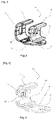
- the figure 1 is an illustration of a hose clamp assembly of the invention.
- the clamp assembly is designated by the general reference 10.
- the clamp assembly 10 is used to support a tubular article such as the tube 100 which can be a rigid tube, a flexible pipe or electrical wiring among other components.
- the tube 100 can be replaced by any other type of element to be supported.
- the hose clamp assembly 10 is intended to hold a cooling line, a fuel line or a brake line of an automobile.
- the clamp assembly 10 comprises a clamping zone 12 or housing of substantially cylindrical annular general shape configured to be engaged around the article 100.
- the clamp assembly 10 also includes a fixing tab 14 arranged to fix the tubular article 100 to an external support (not shown), for example equipment of a motor vehicle by various techniques. These support attachment techniques may include, but are not limited to, gluing, brazing, or welding. In the preferred embodiment of the invention, the clamp assembly 10 is attached to the external support, for example, by means of a threaded fastener.
- the fixing lug 14 comprises in this example one or more fixing holes 16.
- this fixing hole 16 makes it possible to fix the assembly assembly 10 to an external support structure, for example a chassis or an engine block, by means of a fixing element such as a screw (not shown).
- the clamp assembly 10 includes a deformable insert 20 to define the substantially cylindrical clamping zone or cavity 12 intended to receive the tubular element 100. 10 further comprises a peripheral metal body 22 or wrapping body 22 bent to form a generally U-shaped recess within which the insert 20 is wrapped.
- the insert 20 is sized to attach to the wrap support 22 and to conform to the outer diameter of the tube 100.
- the insert 20 is for example made of a molded elastomeric material.
- the type of elastomer material and the hardness can be chosen according to the requirements of a specific application.
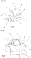
- the insert 20 is molded in an open position illustrated for example on the figures 4 to 6 and is elastically deformable between this open position (undeformed state) and a closed position (deformed state).
- the insert 20 In the open position, the insert 20 has a generally semi-tubular shape with a U-shaped cross section comprising a bottom 26 and side walls 24.
- the insert 20 is open along its length.
- the insert 20 is designed so that when closed, as seen in the picture 1 or 2 , the insert 20 preferably takes on a generally cylindrical shape having a round cross-section with a circular inside diameter which forms the cylindrical cavity of the clamp assembly 10.
- insert 20 includes a radial projection 28 extending radially outward from insert 20.
- Radial projection 28 extends from a middle portion of bottom 26 of insert 20.
- the enveloping body 22 provides a generally U-shaped curved or enveloping portion in which an orifice 23 is provided.
- Orifice 23 is sized to receive radial projection 28 and is configured to cooperate with projection 28 to position insert 20 relative to enveloping body 22.
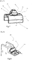
- the projection 28 comprises a base 30 fixed to the insert 20 and a head 32 connected to said base 30 by a connection portion 34 extending radially.
- the projection 28 is provided, at the periphery of the head 32, with a projecting clipping edge 36 to hold the insert 20 in place with respect to the metal casing body 22.
- the radial projection 28 facilitates the maintenance of the insert 20 inside the casing body 22 in the open position.
- the radial projection 28 is dimensioned such that the dimension in at least one direction of the head 32 is greater than the width of the slot or orifice 23 in the body of the clamping sleeve 22. Therefore, in use , the head 32 deforms temporarily to pass through the slot 23, then the head 32 resumes its initial shape to retain the insert 20 on the casing body 24.
- the projection 28 retains the insert 20 inside the wrap body 22, which allows the clamp assembly 10 to come pre-assembled in an open position ( FIGS.4-5 ).
- the clamp assembly 10 is configured to be closed around the tubular article 100 by a forming tool 200 so as to be folded around the article 100.
- the insert 20 comprises, at the level of the base 30 of the radial projection 28, a through hole 38 aligned radially under the projecting clipping edge 36.
- the head 32 of the projection 28 preferably comprises two protruding clipping edges 36 facing each other along the direction of the length of the projection 28.
- the insert 20 comprises , at the base 30 of the projection 28, two lateral through-holes 38 aligned radially under each of the two protruding clipping edges 36.
- the insert 20 can comprise one or more through-holes 38 as well as one or more protruding edges clipping 36 without departing from the scope of the invention.
- the side through-holes 38 are joined together and form a single through-hole extending below the surface of the head 32.
- the single through-hole has in this example an oblong shape with a longitudinal direction extending along the clipping edges highlights 36.
- connection portion 34 radially connects the head 32 along an outer profile devoid of any edge or shoulder.
- the connection part 34 comprises for example two sections of flexible skirt 40 arranged around the single through-hole 38 and in opposite face-to-face relationship along a width direction of the head 32.
- the contour of the head 32 is inscribed inside the through hole 38.
- the contour of the through hole 38 substantially follows the contour of the head 32.
- the head 32 is formed for example by a hollow body and extends above the through hole 38 of the insert 20.
- the head 32 extends above the through hole 38 and the connection part 34 laterally connects the head 32 to the base 30 at the periphery of the through hole 38.
- Head 32 of protrusion 28 preferably has a solid shape with four lateral sides.
- the head 32 comprises two opposite sides extending laterally by the two protruding clipping edges 36 and the two other opposite sides extending laterally by the two flexible skirt sections 40 forming the connection portion 34.
- the shape solid a in the present example as illustrated in FIGS.1-6 a general cube shape.
- at least one clipping rim 36 has a profile in the general shape of an inclined ramp facilitating the progressive introduction of the head 32 through the slot 23.
- the flexible connection portion 34 is in the form of a membrane which can stretch and flex during insertion to allow the bending edges 36 to hook through the orifice 23 made in the body of the device. envelope 22.
- the head 32 of the projection 28 may have the overall shape of a truncated quadrilateral pyramid or may have any other structure or shape allowing the clipping function to be performed.
- the insert 20 as a whole is produced by injection molding of an elastomeric plastic material in a free molding cavity of a molding die (not shown).
- a molding die comprising a mould, for example in two parts in order to delimit at least one free molding cavity inside which can be injected plastic material in the molten state.
- This free molding cavity is configured to conform the insert with the projection 28.
- the mold is then closed and a plastic material in the molten state is injected into the mold. This plastic material fills the free cavity of the mould.
- the mold is opened to extract the molded insert 20. Thanks to the presence of at least one through hole 38 extending under the projecting rim 36 of the head 32 of the projection 28 , the molding process is very simplified because the removal of the mold is facilitated by the presence of the through hole 38.
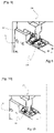
- FIGS. 8 to 10 illustrate part of the method of assembling the clamp assembly according to the invention.
- the figure 8 illustrates a first step of placing the metal clamp holder 22 into a forming tool 200 which includes a holder 204 where the holder assembly 10 is positioned.
- Bracket 204 includes a shaft or mechanical device that cooperates with additional hole 16 of bracket assembly 10.
- the forming tool 200 includes a U-shaped deformation clamp 202 which includes a deformation surface for applying a clamping force to the body of the support shell 22 leading to its plastic deformation and the deformation of the elastomeric insert 20 of the support assembly 10.
- the tubular element 100 is placed in the fixing space of the elastomeric insert 20 of the support assembly 10.
- the figure 10 then illustrates a final step consisting in actuating the forming tool 200 to plastically deform the second end of the metal support 22 around the casing element 100 and to grip the casing element 100, the elastomeric insert 20 being simultaneously bent in order to surround the casing element 100.
- the invention is not limited to the embodiments described above. Other embodiments within the reach of those skilled in the art can also be envisaged without departing from the scope of the invention defined by the claims below.
- the general shape of the head can be cylindrical, oblong, oval in cross-section.
- the number of projecting rims can be one or more without departing from the scope of the invention. 1
Landscapes
- Engineering & Computer Science (AREA)
- General Engineering & Computer Science (AREA)
- Mechanical Engineering (AREA)
- Clamps And Clips (AREA)
- Supports For Pipes And Cables (AREA)
- Connection Of Plates (AREA)
- Insertion Pins And Rivets (AREA)
Applications Claiming Priority (1)
| Application Number | Priority Date | Filing Date | Title |
|---|---|---|---|
| FR2107952A FR3125576B1 (fr) | 2021-07-22 | 2021-07-22 | Ensemble de collier de fixation d’un article tubulaire sur un support externe. |
Publications (1)
| Publication Number | Publication Date |
|---|---|
| EP4123204A1 true EP4123204A1 (de) | 2023-01-25 |
Family
ID=78820868
Family Applications (1)
| Application Number | Title | Priority Date | Filing Date |
|---|---|---|---|
| EP22185388.0A Withdrawn EP4123204A1 (de) | 2021-07-22 | 2022-07-18 | Anordnung zum klemmen eines rohrförmigen gegenstandes auf einem externen träger |
Country Status (4)
| Country | Link |
|---|---|
| US (1) | US11953130B2 (de) |
| EP (1) | EP4123204A1 (de) |
| JP (1) | JP2023017732A (de) |
| FR (1) | FR3125576B1 (de) |
Families Citing this family (2)
| Publication number | Priority date | Publication date | Assignee | Title |
|---|---|---|---|---|
| US20250250011A1 (en) * | 2024-02-01 | 2025-08-07 | B/E Aerospace, Inc. | Composite beam joint for aircraft seat frame |
| US12313196B1 (en) * | 2024-02-27 | 2025-05-27 | Ford Global Technologies, Llc | Clamp for a pipe |
Citations (5)
| Publication number | Priority date | Publication date | Assignee | Title |
|---|---|---|---|---|
| US3564676A (en) * | 1967-10-25 | 1971-02-23 | Ges Fuer Technischen Fortschritt Mbh | Noise-attenuating pipe fastener |
| US5806813A (en) | 1997-01-06 | 1998-09-15 | Lab Holding Company | Tubing bracket assembly |
| US9482369B2 (en) | 2009-03-25 | 2016-11-01 | Franklin Fastener Company | Wrap bracket damper assembly |
| US20180326933A1 (en) * | 2017-05-15 | 2018-11-15 | Autotube Aktiebolag | Bracket and bracket assembly |
| DE102018109617A1 (de) * | 2018-04-20 | 2019-10-24 | Elringklinger Ag | Spannvorrichtung zum Abdichten und Verbinden zweier Rohre |
Family Cites Families (7)
| Publication number | Priority date | Publication date | Assignee | Title |
|---|---|---|---|---|
| US2250280A (en) * | 1940-05-14 | 1941-07-22 | Maurice M Starbird | Electrical bond |
| US5009376A (en) * | 1989-04-26 | 1991-04-23 | Usui Kokusai Sangyo Kaisha Ltd. | Seizure-fixing device of pipe by clamp member |
| US8439317B2 (en) * | 2009-02-27 | 2013-05-14 | Franklin Fastener Company | Grommeted clamp assembly |
| FR2950662B1 (fr) * | 2009-09-28 | 2011-10-28 | Snecma | Dispositif de fixation d'un element de forme allongee sur un carter de turbomachine |
| BR102012024461B1 (pt) * | 2012-09-26 | 2021-04-20 | Tigre S.A. Participações | abraçadeira para fixação de tubos |
| US20170030486A1 (en) * | 2015-07-28 | 2017-02-02 | Franklin Fastener Company | Captivating clamp |
| US10668878B1 (en) * | 2019-02-08 | 2020-06-02 | Franklin Fastener Company | Wrap bracket with attached push-on nut |
-
2021
- 2021-07-22 FR FR2107952A patent/FR3125576B1/fr active Active
-
2022
- 2022-07-18 EP EP22185388.0A patent/EP4123204A1/de not_active Withdrawn
- 2022-07-22 US US17/871,238 patent/US11953130B2/en active Active
- 2022-07-22 JP JP2022117092A patent/JP2023017732A/ja active Pending
Patent Citations (6)
| Publication number | Priority date | Publication date | Assignee | Title |
|---|---|---|---|---|
| US3564676A (en) * | 1967-10-25 | 1971-02-23 | Ges Fuer Technischen Fortschritt Mbh | Noise-attenuating pipe fastener |
| US5806813A (en) | 1997-01-06 | 1998-09-15 | Lab Holding Company | Tubing bracket assembly |
| US9482369B2 (en) | 2009-03-25 | 2016-11-01 | Franklin Fastener Company | Wrap bracket damper assembly |
| US20180326933A1 (en) * | 2017-05-15 | 2018-11-15 | Autotube Aktiebolag | Bracket and bracket assembly |
| DE102018109617A1 (de) * | 2018-04-20 | 2019-10-24 | Elringklinger Ag | Spannvorrichtung zum Abdichten und Verbinden zweier Rohre |
| EP3781856B1 (de) * | 2018-04-20 | 2022-05-04 | ElringKlinger AG | Spannvorrichtung zum abdichten und verbinden zweier rohre |
Also Published As
| Publication number | Publication date |
|---|---|
| FR3125576A1 (fr) | 2023-01-27 |
| JP2023017732A (ja) | 2023-02-07 |
| US11953130B2 (en) | 2024-04-09 |
| US20230046790A1 (en) | 2023-02-16 |
| FR3125576B1 (fr) | 2026-03-06 |
Similar Documents
| Publication | Publication Date | Title |
|---|---|---|
| EP0911565B1 (de) | Schnellverbindung zur Verbindung von starren Rohren in einem Anschlussstück | |
| EP0469949B1 (de) | Vorrichtung zur schnellen Verbindung eines Schlauches mit einem Automobilwärmetauscher | |
| EP2156088B1 (de) | Spannvorrichtung | |
| EP1064489A1 (de) | Steck-kupplung für rohre | |
| EP1497582B1 (de) | Undurchlässige verbindungsvorrichtung, insbesondere für das motorlufteinlasssystem eines kraftfahrzeugs | |
| FR2588354A1 (fr) | Dispositif de raccordement d'un tuyau elastiquement deformable a un tube rigide | |
| FR3066240A1 (fr) | Support et ensemble support | |
| FR2738893A1 (fr) | Procede de realisation d'un embout, embout et connecteur realises par ce procede et circuit comportant un tel connecteur | |
| FR2637021A1 (fr) | Dispositif de regulation de la pression du carburant d'un moteur a injection, presentant une grande facilite de montage et de demontage | |
| EP3734129A1 (de) | Verschlussvorrichtung, die eine schelle und eine dichtungsfuge umfasst | |
| FR3125576A1 (fr) | Ensemble de collier de fixation d’un article tubulaire sur un support externe. | |
| FR2742857A1 (fr) | Plaque collectrice pour echangeur de chaleur | |
| EP1055079A1 (de) | Rohrförmiges element mit einem starren und einem nachgiebigen querteil in einem stück für eine rohrleitung | |
| EP0465288B1 (de) | Vorrichtung zum Befestigen von Beschichtungsplatten auf einer Unterlage und mit Hilfe dieser Vorrichtung erhaltene Anordnung | |
| FR2726625A1 (fr) | Dispositif de mise en forme d'un conduit en matiere plastique ou en matiere elastiquement deformable | |
| EP0396455A1 (de) | Einrastvorrichtung für Kraftfahrzeugwärmetauscher | |
| WO2006045915A1 (fr) | Jonc de verrouillage segmente, assemblage et procede de montage correspondants | |
| FR2690966A3 (fr) | Outil destiné à désaérer des systèmes hydrauliques. | |
| EP1941201A2 (de) | Verbindungsvorrichtung mit geschweisstem körper | |
| FR2922475A1 (fr) | Procede de fabrication d'un dispositif de raccordement de canalisations de fluide | |
| FR2775753A1 (fr) | Collier de serrage pour tubes a connecter, en particulier tubes d'echappement | |
| EP0470918B1 (de) | Verbindung zwischen Rohrelementen | |
| BE559369A (de) | ||
| FR2564563A1 (fr) | Dispositif pour fixer l'extremite d'un tuyau souple a un raccord | |
| FR2674491A1 (fr) | Dispositif de positionnement pour raccords de canalisations d'installations hydrauliques pour vehicules automobiles, notamment pour groupes de servodirection hydraulique. |
Legal Events
| Date | Code | Title | Description |
|---|---|---|---|
| PUAI | Public reference made under article 153(3) epc to a published international application that has entered the european phase |
Free format text: ORIGINAL CODE: 0009012 |
|
| STAA | Information on the status of an ep patent application or granted ep patent |
Free format text: STATUS: THE APPLICATION HAS BEEN PUBLISHED |
|
| AK | Designated contracting states |
Kind code of ref document: A1 Designated state(s): AL AT BE BG CH CY CZ DE DK EE ES FI FR GB GR HR HU IE IS IT LI LT LU LV MC MK MT NL NO PL PT RO RS SE SI SK SM TR |
|
| STAA | Information on the status of an ep patent application or granted ep patent |
Free format text: STATUS: REQUEST FOR EXAMINATION WAS MADE |
|
| 17P | Request for examination filed |
Effective date: 20230601 |
|
| RBV | Designated contracting states (corrected) |
Designated state(s): AL AT BE BG CH CY CZ DE DK EE ES FI FR GB GR HR HU IE IS IT LI LT LU LV MC MK MT NL NO PL PT RO RS SE SI SK SM TR |
|
| STAA | Information on the status of an ep patent application or granted ep patent |
Free format text: STATUS: EXAMINATION IS IN PROGRESS |
|
| 17Q | First examination report despatched |
Effective date: 20231220 |
|
| GRAP | Despatch of communication of intention to grant a patent |
Free format text: ORIGINAL CODE: EPIDOSNIGR1 |
|
| STAA | Information on the status of an ep patent application or granted ep patent |
Free format text: STATUS: GRANT OF PATENT IS INTENDED |
|
| RIC1 | Information provided on ipc code assigned before grant |
Ipc: F16L 55/035 20060101ALN20241125BHEP Ipc: B21D 39/04 20060101ALI20241125BHEP Ipc: F16L 3/123 20060101AFI20241125BHEP |
|
| INTG | Intention to grant announced |
Effective date: 20241210 |
|
| RIC1 | Information provided on ipc code assigned before grant |
Ipc: F16L 55/035 20060101ALN20241202BHEP Ipc: B21D 39/04 20060101ALI20241202BHEP Ipc: F16L 3/123 20060101AFI20241202BHEP |
|
| STAA | Information on the status of an ep patent application or granted ep patent |
Free format text: STATUS: THE APPLICATION IS DEEMED TO BE WITHDRAWN |
|
| 18D | Application deemed to be withdrawn |
Effective date: 20250411 |