EP4126604B1 - Dispositif de nettoyage pour une visière - Google Patents
Dispositif de nettoyage pour une visière Download PDFInfo
- Publication number
- EP4126604B1 EP4126604B1 EP21705571.4A EP21705571A EP4126604B1 EP 4126604 B1 EP4126604 B1 EP 4126604B1 EP 21705571 A EP21705571 A EP 21705571A EP 4126604 B1 EP4126604 B1 EP 4126604B1
- Authority
- EP
- European Patent Office
- Prior art keywords
- viewing window
- cleaning device
- window
- vibration element
- cleaning
- Prior art date
- Legal status (The legal status is an assumption and is not a legal conclusion. Google has not performed a legal analysis and makes no representation as to the accuracy of the status listed.)
- Active
Links
Images



Classifications
-
- B—PERFORMING OPERATIONS; TRANSPORTING
- B08—CLEANING
- B08B—CLEANING IN GENERAL; PREVENTION OF FOULING IN GENERAL
- B08B11/00—Cleaning flexible or delicate articles by methods or apparatus specially adapted thereto
-
- B—PERFORMING OPERATIONS; TRANSPORTING
- B08—CLEANING
- B08B—CLEANING IN GENERAL; PREVENTION OF FOULING IN GENERAL
- B08B13/00—Accessories or details of general applicability for machines or apparatus for cleaning
-
- B—PERFORMING OPERATIONS; TRANSPORTING
- B08—CLEANING
- B08B—CLEANING IN GENERAL; PREVENTION OF FOULING IN GENERAL
- B08B17/00—Methods preventing fouling
- B08B17/02—Preventing deposition of fouling or of dust
-
- B—PERFORMING OPERATIONS; TRANSPORTING
- B08—CLEANING
- B08B—CLEANING IN GENERAL; PREVENTION OF FOULING IN GENERAL
- B08B7/00—Cleaning by methods not provided for in a single other subclass or a single group in this subclass
- B08B7/02—Cleaning by methods not provided for in a single other subclass or a single group in this subclass by distortion, beating, or vibration of the surface to be cleaned
- B08B7/026—Using sound waves
- B08B7/028—Using ultrasounds
-
- B—PERFORMING OPERATIONS; TRANSPORTING
- B60—VEHICLES IN GENERAL
- B60J—WINDOWS, WINDSCREENS, NON-FIXED ROOFS, DOORS, OR SIMILAR DEVICES FOR VEHICLES; REMOVABLE EXTERNAL PROTECTIVE COVERINGS SPECIALLY ADAPTED FOR VEHICLES
- B60J1/00—Windows; Windscreens; Accessories therefor
- B60J1/002—Windows; Windscreens; Accessories therefor with means for clear vision, e.g. anti-frost or defog panes, rain shields
-
- B—PERFORMING OPERATIONS; TRANSPORTING
- B60—VEHICLES IN GENERAL
- B60Q—ARRANGEMENT OF SIGNALLING OR LIGHTING DEVICES, THE MOUNTING OR SUPPORTING THEREOF OR CIRCUITS THEREFOR, FOR VEHICLES IN GENERAL
- B60Q1/00—Arrangement of optical signalling or lighting devices, the mounting or supporting thereof or circuits therefor
- B60Q1/0005—Devices preventing the lights from becoming dirty or damaged, e.g. protection grids or cleaning by air flow
-
- B—PERFORMING OPERATIONS; TRANSPORTING
- B60—VEHICLES IN GENERAL
- B60S—SERVICING, CLEANING, REPAIRING, SUPPORTING, LIFTING, OR MANOEUVRING OF VEHICLES, NOT OTHERWISE PROVIDED FOR
- B60S1/00—Cleaning of vehicles
- B60S1/02—Cleaning windscreens, windows or optical devices
-
- B—PERFORMING OPERATIONS; TRANSPORTING
- B60—VEHICLES IN GENERAL
- B60S—SERVICING, CLEANING, REPAIRING, SUPPORTING, LIFTING, OR MANOEUVRING OF VEHICLES, NOT OTHERWISE PROVIDED FOR
- B60S1/00—Cleaning of vehicles
- B60S1/02—Cleaning windscreens, windows or optical devices
- B60S1/023—Cleaning windscreens, windows or optical devices including defroster or demisting means
-
- B—PERFORMING OPERATIONS; TRANSPORTING
- B60—VEHICLES IN GENERAL
- B60S—SERVICING, CLEANING, REPAIRING, SUPPORTING, LIFTING, OR MANOEUVRING OF VEHICLES, NOT OTHERWISE PROVIDED FOR
- B60S1/00—Cleaning of vehicles
- B60S1/02—Cleaning windscreens, windows or optical devices
- B60S1/023—Cleaning windscreens, windows or optical devices including defroster or demisting means
- B60S1/026—Cleaning windscreens, windows or optical devices including defroster or demisting means using electrical means
-
- B—PERFORMING OPERATIONS; TRANSPORTING
- B60—VEHICLES IN GENERAL
- B60S—SERVICING, CLEANING, REPAIRING, SUPPORTING, LIFTING, OR MANOEUVRING OF VEHICLES, NOT OTHERWISE PROVIDED FOR
- B60S1/00—Cleaning of vehicles
- B60S1/02—Cleaning windscreens, windows or optical devices
- B60S1/56—Cleaning windscreens, windows or optical devices specially adapted for cleaning other parts or devices than front windows or windscreens
-
- B—PERFORMING OPERATIONS; TRANSPORTING
- B60—VEHICLES IN GENERAL
- B60S—SERVICING, CLEANING, REPAIRING, SUPPORTING, LIFTING, OR MANOEUVRING OF VEHICLES, NOT OTHERWISE PROVIDED FOR
- B60S1/00—Cleaning of vehicles
- B60S1/02—Cleaning windscreens, windows or optical devices
- B60S1/56—Cleaning windscreens, windows or optical devices specially adapted for cleaning other parts or devices than front windows or windscreens
- B60S1/60—Cleaning windscreens, windows or optical devices specially adapted for cleaning other parts or devices than front windows or windscreens for signalling devices, e.g. reflectors
- B60S1/603—Cleaning windscreens, windows or optical devices specially adapted for cleaning other parts or devices than front windows or windscreens for signalling devices, e.g. reflectors the operation of at least a part of the cleaning means being controlled by electric means
-
- F—MECHANICAL ENGINEERING; LIGHTING; HEATING; WEAPONS; BLASTING
- F21—LIGHTING
- F21S—NON-PORTABLE LIGHTING DEVICES; SYSTEMS THEREOF; VEHICLE LIGHTING DEVICES SPECIALLY ADAPTED FOR VEHICLE EXTERIORS
- F21S41/00—Illuminating devices specially adapted for vehicle exteriors, e.g. headlamps
- F21S41/20—Illuminating devices specially adapted for vehicle exteriors, e.g. headlamps characterised by refractors, transparent cover plates, light guides or filters
- F21S41/2805—Cover glass
-
- F—MECHANICAL ENGINEERING; LIGHTING; HEATING; WEAPONS; BLASTING
- F21—LIGHTING
- F21S—NON-PORTABLE LIGHTING DEVICES; SYSTEMS THEREOF; VEHICLE LIGHTING DEVICES SPECIALLY ADAPTED FOR VEHICLE EXTERIORS
- F21S45/00—Arrangements within vehicle lighting devices specially adapted for vehicle exteriors, for purposes other than emission or distribution of light
- F21S45/60—Heating of lighting devices, e.g. for demisting
-
- G—PHYSICS
- G02—OPTICS
- G02B—OPTICAL ELEMENTS, SYSTEMS OR APPARATUS
- G02B1/00—Optical elements characterised by the material of which they are made; Optical coatings for optical elements
- G02B1/10—Optical coatings produced by application to, or surface treatment of, optical elements
- G02B1/11—Anti-reflection coatings
-
- G—PHYSICS
- G02—OPTICS
- G02B—OPTICAL ELEMENTS, SYSTEMS OR APPARATUS
- G02B1/00—Optical elements characterised by the material of which they are made; Optical coatings for optical elements
- G02B1/10—Optical coatings produced by application to, or surface treatment of, optical elements
- G02B1/18—Coatings for keeping optical surfaces clean, e.g. hydrophobic or photo-catalytic films
-
- G—PHYSICS
- G02—OPTICS
- G02B—OPTICAL ELEMENTS, SYSTEMS OR APPARATUS
- G02B27/00—Optical systems or apparatus not provided for by any of the groups G02B1/00 - G02B26/00, G02B30/00
- G02B27/0006—Optical systems or apparatus not provided for by any of the groups G02B1/00 - G02B26/00, G02B30/00 with means to keep optical surfaces clean, e.g. by preventing or removing dirt, stains, contamination, condensation
-
- B—PERFORMING OPERATIONS; TRANSPORTING
- B08—CLEANING
- B08B—CLEANING IN GENERAL; PREVENTION OF FOULING IN GENERAL
- B08B7/00—Cleaning by methods not provided for in a single other subclass or a single group in this subclass
- B08B7/02—Cleaning by methods not provided for in a single other subclass or a single group in this subclass by distortion, beating, or vibration of the surface to be cleaned
Definitions
- the invention relates to a cleaning device for a window, in particular of a vehicle, having the features of the preamble of independent claim 1.
- headlight cleaning systems have long been known in which a cleaning fluid is sprayed from the outside onto one or more cover plates of a headlight using high pressure.
- a cleaning fluid is sprayed from the outside onto one or more cover plates of a headlight using high pressure.
- This type of contamination of the cover plate can be reliably removed.
- the disadvantage of such headlight cleaning systems is that they consist of numerous parts and components that are prone to errors and require a lot of maintenance.
- Such high-pressure washing systems which usually have a high consumption of washing fluid, therefore require storage tanks containing several liters of washing fluid.
- the washing fluid used is usually water with appropriate additives, such as an appropriate insect remover in summer or a suitable antifreeze in winter.
- the nozzles of such a high-pressure system spray the water from movable nozzles onto the cover plates of the headlights from the outside at pressures of up to 50 bar. If unsuitable additives are used, the cover panes can become cloudy prematurely, which is another disadvantage of these previously known cleaning systems.
- the legislator also checks the functionality of vehicles equipped with such headlight cleaning systems. Vehicle owners who are bothered by the high water consumption of their headlight cleaning system and therefore have it deactivated risk having their vehicle's operating license revoked.
- headlight cleaning systems are problematic from the point of view of pedestrian protection, since the movable high-pressure cleaning nozzles, which are usually integrated in the area of the front bumper, increase the risk of injury in the event of a collision between the vehicle and a pedestrian.
- FR 2 841 488 A1 a cleaning device for a window of a vehicle.
- the US 10 401 618 B2 describes an ultrasonic cleaning system.
- the publication US 2019/077377 A1 describes a cleaning system for sensors.
- optical sensors In addition to the actual headlights, modern motor vehicles usually also have numerous optical devices installed, such as optical sensors, cameras and see-through displays. These optical devices are usually protected from the effects of the weather or from dirt by cover panels.
- optical sensors can be integrated into headlight systems and/or rear light systems or can be arranged behind the windshield, rear window or side windows of a motor vehicle.
- the conventional headlight cleaning systems mentioned above from the state of the art are not suitable for keeping the field of view (FOV), i.e. the area in the angle of view of an optical device, a sun sensor, the image area of a camera or a camera recording sensor, free from contamination, condensation and/or icing.
- FOV field of view
- Optical sensors and cameras have significantly higher requirements for a clear view with regard to cleaning, defrosting or defrosting of such cover panes, as otherwise the reliable functioning of such sensors and cameras cannot be guaranteed.
- the present invention therefore aims to overcome the disadvantages known from the prior art for cleaning systems for cover windows of a vehicle and to provide a cleaning device that is constructed as cost-effectively and compactly as possible with as few components and assemblies as possible and that ensures a clear view for sensitive optical devices and optical sensors, which are installed in a vehicle in particular, with as little wear and maintenance as possible. Furthermore, the object of the invention is to provide a cleaning device that can operate as efficiently as possible without the use of washing fluid or other consumables.
- a cleaning device according to the invention for a viewing window advantageously enables a viewing window equipped in this way to meet particularly high requirements as a cover for optical sensors or cameras, in particular of a vehicle.
- the field of view of an optical device for example a sun sensor, the image area of a camera or a camera recording sensor
- an optical device for example a sun sensor, the image area of a camera or a camera recording sensor
- the at least one vibration element can be attached directly to the viewing window or the vibration element can be arranged on a further element such as a counterweight, with the counterweight underneath being attached to the viewing window.
- the vibration element is attached to the viewing window, but with a further layer such as a counterweight between the viewing window and the vibration element.
- the viewing window can be attached to a carrier panel or to a corresponding frame that is coupled to the at least one vibration element.
- the carrier panel or frame of the viewing window can be vibrated and the vibrations of the at least one vibration element are transmitted directly to the viewing window. Attaching the vibration element to the cover panel offers the advantage that the oscillations or vibrations are introduced locally into the cover panel and cleaning of the cover panel is therefore particularly efficient.
- the at least one vibration element can comprise, for example, an ultrasonic oscillator which causes the viewing window to vibrate directly or - in the case of a carrier panel or frame of the viewing window coupled to the vibration element - indirectly at frequencies in the ultrasonic range from 16 kHz and thus ensures that contaminants, for example in the form of dirt particles, water droplets or ice deposits, are shaken off the viewing window.
- an ultrasonic oscillator which causes the viewing window to vibrate directly or - in the case of a carrier panel or frame of the viewing window coupled to the vibration element - indirectly at frequencies in the ultrasonic range from 16 kHz and thus ensures that contaminants, for example in the form of dirt particles, water droplets or ice deposits, are shaken off the viewing window.
- So-called nano-coatings which make use of the lotus effect, can be used as a hydrophobic and dirt-repellent coating. Dirt and the surface experience very little adhesion force. Moisture and dirt particles are trapped in the water that runs off and the dirt simply rolls off the hydrophobic coating.
- scratch-resistant, weatherproof coating materials that harden through UV radiation and offer protection for viewing panes made of optically transparent polycarbonate (PC) or polymethyl methacrylate (PMMA), for example, against abrasion, chemical damage, erosion or yellowing due to UV radiation, as well as against dirt, can be applied as a hydrophobic and dirt-repellent coating to the outside of the viewing pane.
- Such coatings which serve as weather protection for cover panes, are also referred to as silicone hardcoats.
- silicone hardcoats for example, such a coating material, which is used for weatherproofing and dirt-repellent suitable for coating vehicle headlight lenses, sold by Momentive Performance Materials Inc. (www.momentive.com) under the product name SilFORT* UVHC5000.
- the at least one vibration element can be attached to the viewing window.
- This design offers the advantage that vibrations can be transmitted to the viewing window particularly efficiently and with as little loss as possible using one or more vibration elements that are attached directly to the viewing window. It is also conceivable within the scope of the invention that at least one counterweight is attached to the viewing window and that at least one vibration element is coupled to the counterweight. Vibrations of the vibration element, which is coupled to the counterweight, are transmitted from the vibration element to the counterweight and from there, amplified, directly to the viewing window. The vibrating effect of the vibration element is amplified as a resonance of the counterweight coupled to it, thus further improving the cleaning effect of the viewing window.
- the at least one vibration element can be integrated into the viewing window.
- At least one vibration element is integrated into the viewing window in a particularly effective way to protect it from damage or weather influences. Vibrations from the vibration element, which are activated by the control unit, are advantageously introduced directly into the viewing window on site for the desired cleaning. Vibration losses are thus reliably avoided.
- one or more vibration elements can be integrated into the viewing window during the manufacturing process using insert molding or injection molding by inserting the vibration element in the injection molding process.
- the cleaning device is designed so that at least one vibration element is coupled to a carrier panel to which the viewing window is attached.
- a carrier panel is a frame for the viewing window.
- the one or more vibration elements is/are integrated directly into the carrier panel.
- Such a carrier panel or frame offers the advantage that the viewing window is protected at its edges by the carrier panel and the vibrations are evenly introduced into the viewing window. The viewing window is therefore also protected as well as possible from mechanical stress during cleaning operations, i.e. while vibrations are being introduced by the at least one vibration element.
- a cleaning device according to the invention can be designed to be particularly compact if the at least one vibration element is integrated in the carrier panel of the viewing window.
- the viewing window can be connected to the carrier panel in one piece and can be replaced or exchanged together with the carrier panel or at least together with a frame if necessary.
- the at least one vibration element in a cleaning device, can be permanently connected to the viewing window and/or to the carrier panel by joining.
- joining covers various joining processes. During joining, two or more solid bodies, the joining parts, with a geometrically defined shape are permanently connected or joined together. In some joining processes, an "amorphous" auxiliary material, i.e. a material whose shape is not defined, is also used. Adhesives, for example, are understood to be such an auxiliary material.
- the optically transparent anti-fogging device can be a fog-inhibiting coating which is applied to the inside of the viewing window.
- This design offers the advantage that the viewing window can be cleaned not only on the outside to protect it from external contamination and weather influences, but also on the inside.
- the inside is the side of the viewing window opposite the outside, which in the installed position, for example in a headlight, particularly a vehicle headlight, is oriented towards the housing of the headlight.
- the inside of the viewing window is equipped with an anti-fog coating in this embodiment of the invention.
- anti-fog Such coatings, known as “anti-fog”, are available, for example, for cover panels made of transparent polycarbonate (PC) or polymethyl methacrylate (PMMA) under the name MODIPER ® H from the manufacturer NOF Corporation (www.nof.co.jp).
- the optically transparent anti-fogging device in a cleaning device, can comprise a heating element with a heating foil and/or with heating wires, wherein the heating foil and/or heating wires are attached to the inside of the viewing window or at least partially integrated into the viewing window.
- a heating foil and/or a heating element with heating wires integrated into the pane can also be provided on the inside of the pane.
- Such electrical components can be conveniently controlled and activated by the same control unit that is used to activate the at least one vibration element. If necessary, condensation on the inside of the pane can be quickly prevented and condensation on the inside of the pane can be quickly dried off.
- an anti-reflective coating can be applied to the outside and/or inside of the viewing window in a cleaning device.
- An anti-reflective coating also known as anti-reflection coating, offers the advantage that transmission losses are greatly reduced.
- Self-glare from light modules is prevented as far as possible. This increases the efficiency of the camera sensors.
- an anti-reflective coating on the viewing window can be beneficial for reducing noise, which also increases the efficiency of the corresponding sensors.
- the at least one vibration element is a piezo element generating ultrasonic vibrations.
- Piezoelectric vibrators i.e. resonantly operated piezo actuators that are used to generate ultrasound at frequencies of 16 kHz to 200 kHz, offer the advantage of a particularly compact design, which is particularly important when used in vibration elements that are as small as possible or in compact vibration units that are attached as inconspicuously as possible to the cover plate of headlights or vehicle headlights. Due to the small size of such piezo actuators or piezoelectric vibrators, they can also be integrated directly into the cover plate, which - as already mentioned - can further increase the efficiency of the cleaning device.
- a cleaning device can clean a viewing window particularly efficiently if two or more spaced-apart vibration elements are coupled to the viewing window, wherein the two or more vibration elements can each be activated by a control device.
- vibration elements can be arranged distributed over the surface of a viewing window or coupled to the viewing window at sections spaced apart from one another. It is advisable to select positions for the vibration elements on the viewing window or along it that are not directly in the optical beam path of a sensor or camera located under the viewing window and thus do not interfere with the sensor or camera.
- control device interacts with a camera and/or with a sensor, preferably an optical sensor.
- the signal-based coupling of the cleaning device or its control unit with a camera and/or a suitable sensor that detects soiling of the viewing window offers the advantage that the cleaning device is automatically activated as required.
- a camera can detect whether the current weather conditions, for example during rain or snowfall, make it necessary to clean the viewing window.
- the activation of the at least one vibration element is carried out by the control unit according to an activation scheme which is selected from the group comprising: cyclically recurring activation, manual activation, activation by means of a sensor signal, activation by means of a camera signal.
- the at least one vibration element of the cleaning device can be activated and operated by the control unit at different frequencies and/or amplitudes and/or time intervals and/or durations.
- different cleaning programs can be set with the cleaning device in order to be able to clean the viewing window equipped with the cleaning device as efficiently as possible, adapted to the respective individual cleaning task.
- it can be expedient if the cleaning of the viewing window takes place in dry weather with an example higher frequency and amplitude of the vibrations of the at least one vibration element than during cleaning in rainy weather.
- damp weather with precipitation it may be sufficient if the cleaning of the viewing window to shake off raindrops and moisture takes place at a comparatively lower frequency and a smaller amplitude of the vibrations of the one or more vibration elements than is appropriate in dry weather.
- the viewing window coupled to the at least one vibration element is replaceable.
- the viewing window can, for example, be attached as a replaceable module in a carrier panel or a frame and can be easily replaced if necessary. In an alternative design, it can also be useful if the viewing window together with the carrier panel or the frame forms a module and can be easily and inexpensively replaced. This also offers the advantage that electronic components such as optical sensors or a camera, which are installed in a vehicle, for example, and are protected from the weather by a corresponding viewing window, can be easily accessed from the outside by removing the viewing window.
- the viewing window alone or together with a removable carrier panel or frame therefore also serves as an inspection and maintenance cover for the optical components underneath.
- the viewing window or the viewing window together with at least a section of the carrier panel can be opened and closed again, for example using a quick-change fastener or bayonet lock.
- Appropriate seals ensure a hermetic seal between the viewing window and its frame or the surrounding housing, for example of a vehicle headlight, if the viewing window is integrated as a cover for optical components in a vehicle headlight.
- the viewing window in a cleaning device can be arranged within a cover window of a vehicle, wherein the cover window is selected from the following group: windshield, side window, rear window, headlight cover window, optical lens.
- the viewing window equipped with the cleaning device has the most homogeneous properties possible and can form a module within a larger cover window.
- a viewing window can be arranged within a windshield, side window or rear window of a vehicle or integrated into such a window.
- this can be integrated particularly unobtrusively into the surrounding cover window.
- the viewing window can be arranged in a tinted strip on the edge of the respective cover window, for example the windshield.
- the viewing window equipped with the cleaning device can be integrated into a headlight cover of a vehicle or into an optical lens of a headlight.
- the above-mentioned advantages of the cleaning device according to the invention also apply equally to a headlight equipped with a cleaning device, in particular a vehicle headlight.
- the present application refers to one cleaning device in each case.
- the invention also includes headlights that have several cleaning devices, each with a viewing window to cover a particularly sensitive optical sensor or a camera.
- the term cleaning device also includes different designs with one or more vibration elements.
- the invention further provides a vehicle with at least one cleaning device.
- a viewing window equipped with a cleaning device according to the invention which is arranged in a vehicle headlight
- the use of external washing liquid together with the liquid tanks and equipment usually required for this purpose, such as pumps, supply hoses and washing nozzles for spraying the washing liquid onto the cover panes of the vehicle headlight can be dispensed with.
- FIG. 1 in an isometric view obliquely from the front, a vehicle headlight with a viewing window equipped with a cleaning device according to the invention
- - Fig.2 in a partial sectional view from the side a section of the Fig.1 illustrated viewing window including the associated cleaning device
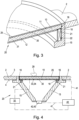
- - Fig.3 in an isometric view obliquely from above the Fig.2 marked detail of viewing window including the associated cleaning device
- - Fig.4 in a sectional view from the side details of a cleaning device including a viewing window attached to a support panel
- - Fig.5 in a plan view a vehicle headlight with a viewing window with a cleaning device according to the invention, wherein additionally several vibration elements for cleaning are integrated in the cover window
- - Fig.6 in an isometric view obliquely from above, a cleaning device attached to a viewing window with a vibration
- the cleaning device 20 for a viewing window 10, which is integrated here for example in a vehicle headlight 1, comprises, in addition to the optically transparent viewing window 10, at least one vibration element 21 which is coupled to the viewing window 10.
- the vibration element 21 is expediently installed in or integrated into a carrier panel 15 which serves as a frame for the viewing window 10.
- the viewing window 10 is made of polymethyl methacrylate (PMMA) and has an outer side 11 and an inner side 12. On its outer side 11, the viewing window 10 is provided with a hydrophobic and dirt-repellent coating 25
- a silicone hardcoat coating is used here as the external dirt-repellent coating 25, which serves as weather protection for the viewing window 10 and is water-repellent (hydrophobic) as well as grease-repellent (oleophobic).
- the coating thickness of this silicone hardcoat coating is, for example, from 8 ⁇ m to 12 ⁇ m.
- An anti-fogging device 30 is attached to the inside 12 of the viewing window 10, for example in the form of a fog-inhibiting coating 31.
- the viewing window 10 can, for example, have a screw thread on its circumference and can be screwed into the carrier panel 15.
- the viewing window 10 is glued to the carrier panel 15 or to the vibration element 21 with an adhesive film 18.
- An intermediate seal 16 between the viewing window 10 and the frame of the carrier panel 15 prevents the unwanted penetration of moisture into the interior of the vehicle headlight protected by the viewing window 10. Undesirable condensation on the inside 12 of the viewing window 10 is thereby prevented as far as possible.
- a vibration element 21 arranged circumferentially around the viewing window 10 can be activated by a control unit not explicitly shown here.
- the vibration element 21 is designed, for example, as a piezo element 22 or as a piezoelectric vibrator 22.
- the piezoelectric vibrator 22 is a resonantly operated piezo actuator that is used to generate ultrasound at frequencies of 16 kHz to 200 kHz.
- the piezoelectric vibrator 22 is attached in an annular notch in the carrier panel 15.
- the vibration element 21 is glued to the inside 12 of the viewing window 10 using adhesive 18 or adhesive films 18.
- the integration of the vibration element 21 within the carrier panel 15 offers the advantage of a closed, encapsulated design.
- the vibration element 21 only needs to be electrically connected to a corresponding control unit in order to be able to be activated by the control unit.
- the carrier panel 15, together with the viewing window 10 and the vibration element 21 integrated in the carrier panel 15, is designed as an exchangeable module and can be easily and inexpensively replaced if required.
- Fig.4 shows from the side details of a cleaning device 20 including a viewing window 10 fastened in a carrier panel 15.
- the arrangement shown here corresponds essentially to the previous description of the Figures 2 and 3 .
- the viewing window 10 is made here, for example, from polymethyl methacrylate (PMMA) and has an outer side 11 and an inner side 12. On its outer side 11, the viewing window 10 is equipped with a hydrophobic and dirt-repellent coating 25 in the form of a silicone hardcoat coating.
- PMMA polymethyl methacrylate
- the anti-fog device 30 is controlled by means of a heating element 32, wherein the heating element 32 is controlled by a central control unit 40 by means of corresponding signal lines 41.
- the viewing window 10 is glued to the carrier panel 15 or to the vibration element 21 with an adhesive film 18.
- An intermediate seal 16 between the viewing window 10 and the frame of the carrier panel 15 prevents the undesired penetration of moisture into the interior protected by the viewing window 10, in which, for example, a photo sensor 42 or a camera 43 is located. Undesirable condensation on the inner side 12 of the viewing window 10 is thereby prevented as far as possible.
- a vibration element 21 arranged circumferentially around the viewing window 10 can be activated by the control unit 40.
- the vibration element 21 is designed, for example, as a piezo element 22 or as a piezoelectric vibrator 22.
- the control unit 40 is connected to the vibration element 21 by means of signal lines 41.
- the photo sensor 42 or the camera 43 detects contamination 29, for example in the form of dirt or raindrops on the outside of the viewing window 10.
- the vibration element 21 is thus activated by the control unit 40 after receiving a signal from the camera 43 or the photo sensor 42.
- the sensor 42 can also be used redundantly, for example, to check the functionality of the vibration element 21 or the camera 43.
- Fig.5 shows a vehicle headlight 1 with a viewing window 10 with a cleaning device 20 according to the invention, wherein the viewing window 10 is arranged within the cover window 2.
- several vibration elements 21 for cleaning are also integrated in the cover window 2.
- the cover window 2 is also provided with a hydrophobic, dirt-repellent coating 25 on its outer side 3.
- the cover window 2 has an anti-fog coating 31.
- the individual vibration elements 21 are connected to a control unit (not explicitly shown) by signal lines 41 and can be activated together from the control unit.
- the viewing window 10 can advantageously be cleaned particularly thoroughly with the cleaning device 20 provided for this purpose in order to ensure the functionality of a sensitive optical sensor or camera located behind or underneath it.
- the cover plate 2 of the vehicle headlight 1 which surrounds the viewing window 10 and which protects the lamps and optical components such as reflectors or lenses of the headlight located underneath in a manner known per se, can also be cleaned by a cleaning device 20.
- the vibration elements 21 can expediently for cleaning both the viewing window 10 and the cover window 2, can be controlled from a central control unit.
- the viewing window 10 has an anti-fogging device with a heating element and a heating foil on its inner side 12. This anti-fogging device can also be regulated and controlled from the central control unit.
- Fig.6 shows a cleaning device 20 attached to a viewing window 10 with a vibration unit 23 in which a vibration element 21 is integrated within a housing 24.
- the vibration unit 23 is glued to the inside 12 of the viewing window 10 by means of an adhesive layer 18.
- the vibration element 21 in the form of a piezo element 12 is connected here to the counterweight. Both the counterweight and the vibration element 21 are directly adjacent to the viewing window 10 within the housing 24. Vibrations of the vibration unit 23 are thus introduced directly and immediately into the viewing window 10 in a particularly efficient manner. Contaminants that are on the outside 11 of the viewing window 10 provided with a hydrophobic coating 25 can thus be shaken off particularly effectively if necessary by means of the resonant vibrations of the piezoelectric vibrator 22.
- vibration units 23 can also be arranged on a cover plate 2 of a vehicle headlight 1 for cleaning, as for example in Fig.5
- the vibration unit 23 is glued to the inner side 4 of the cover plate 2 by means of an adhesive layer 18.
- Fig.7 shows a variant of a cleaning device 20 according to the invention together with the associated control system, wherein a vibration unit 21 is integrated in a viewing window 10.
- the vibration unit 21 is embedded here in a recess in the viewing window 10.
- the cavity was then filled with a crystal-clear hardening adhesive 18 after the vibration unit 21 was embedded.
- a protected interior space 5 of a vehicle headlight 1 in which, for example, a photo sensor 42 or a camera 43 is located.
- the vibration element 21 integrated in the viewing window 10 can be activated by a control unit 40.
- the vibration element 21 is designed, for example, as a piezo element 22 or as a piezoelectric vibrator 22.
- the control unit 40 is connected to the vibration element 21 by means of signal lines 41.
- the photo sensor 42 or the camera 43 detects contamination 29, for example in the form of dirt or raindrops on the outside of the viewing window 10. The activation of the vibration element 21 is thus carried out by the control unit 40 after receiving a signal from the Camera 43 or the photo sensor 42.
- the sensor 42 can, for example, also serve redundantly to check the functionality of the vibration element 21 or the camera 43.
- the anti-fog device 30 is controlled by means of a heating element 32, wherein the heating element 32 is also controlled by the central control unit 40 by means of corresponding signal lines 41.
- Fig.8 shows a further, alternative variant of a cleaning device 20 according to the invention together with the associated control system.
- a detail of a motor vehicle headlight 1 is shown, wherein the viewing window 10 is equipped with a hydrophobic and dirt-repellent coating 25 arranged on the outside 11.
- a vibration unit 23 with a vibration element 21 is attached to the inside 12 of the viewing window 10 by means of an adhesive layer 18.
- the inside 12 is further protected against undesirable condensation by an anti-fogging device 30, for example in the form of a fog-inhibiting coating.
- a control unit 40 is used to activate the vibration element 21.
- the control unit 40 is connected to the vibration element 21 or to a motion sensor 42 coupled to the vibration element 21 by means of signal lines 41.
- Contaminants 29, for example in the form of dirt or raindrops on the viewing window 10 are detected by means of a camera 43, which is arranged in the interior 5 of the headlight 1 and which is also connected to the control unit 40 by a signal line 41.
- the activation of the vibration element 21 is thus carried out by the control unit 40 after receiving a signal from the camera 43.
- the motion sensor 42 serves here to check the functionality of the vibration element 21.
- one or more sensors 42 can also be used to activate the at least one vibration element 21.
- sensors 42 for example rain sensors
- a camera 43 which is positioned in the interior 5 of the vehicle headlight 1 and whose sensitivity can be programmed to determine when contamination is recognized as such and a corresponding camera signal is sent to the control unit 40, offers the advantage that it remains functional even when contamination 29 occurs locally.
- a single small sensor that is attached to the cover plate of the headlight can be masked by locally occurring, heavy contamination 29 on the cover plate and may then not work. For this reason, it is expedient to provide a redundant, as fail-safe as possible activation of the cleaning device 20 when activating the cleaning device 20 by means of sensors 42 and without using a camera.
- an individual sensor 42 in particular an optical sensor, does not function temporarily due to local contamination, the vibration element 21 of the cleaning device 10 for the viewing window 20 can still be activated by the other sensors 42 connected in parallel using the control unit 40.
Landscapes
- Engineering & Computer Science (AREA)
- Physics & Mathematics (AREA)
- Mechanical Engineering (AREA)
- General Physics & Mathematics (AREA)
- Optics & Photonics (AREA)
- General Engineering & Computer Science (AREA)
- Chemical & Material Sciences (AREA)
- Chemical Kinetics & Catalysis (AREA)
- Rear-View Mirror Devices That Are Mounted On The Exterior Of The Vehicle (AREA)
- Non-Portable Lighting Devices Or Systems Thereof (AREA)
- Window Of Vehicle (AREA)
Claims (13)
- Dispositif de nettoyage (20) pour nettoyer une écran de vue (10), en particulier la vitre d'un véhicule,le dispositif de nettoyage (20) comprenant- un écran de support (15),- l'écran de vue optiquement transparente (10) fixée à l'écran de support (15),- un revêtement (25) optiquement transparent, hydrophobe et repoussant les salissures, qui est appliqué sur une face extérieure (11) de l'écran de vue (10),- au moins un élément vibrant (21), ledit au moins un élément vibrant (21) pouvant être activé par un appareil de commande (40) et l'élément vibrant (21) étant conçu pour faire vibrer l'écran de support (15) et pour secouer les impuretés de l'écran de vue (10), ainsi que- un dispositif anti-buée optiquement transparent (30), qui est disposé sur une face intérieure (12) de l'écran de vue (10) et qui est adapté pour que la face intérieure de la vitre reste exempte de dépôt de condensation,caractérisé en ce quele au moins un élément vibrant (21) est couplé à l'écran de support (15) et est intégré dans l'écran de support (15).
- Dispositif de nettoyage (20) selon la revendication 1, dans lequel l'au moins un élément vibrant (21) est fixé à l'écran de vue (10).
- Dispositif de nettoyage (20) selon l'une des revendications 1 ou 2, dans lequel l'au moins un élément vibrant (21) est relié de manière durable à l'écran de vue (10) et/ou à l'écran de support (15) par assemblage.
- Dispositif de nettoyage (20) selon l'une des revendications 1 à 3, dans lequel le dispositif anti-buée optiquement transparent (30) est un revêtement anti-buée (31) appliqué sur la face interne (12) de l'écran de vue (10).
- Dispositif de nettoyage (20) selon l'une des revendications 1 à 4, dans lequel le dispositif anti-buée optiquement transparent (30) comprend un élément chauffant (32) avec une feuille chauffante (34) et/ou des fils chauffants (33), la feuille chauffante (34) et/ou les fils chauffants (33) étant fixés sur la face interne (12) de l'écran de vue (10) ou étant au moins partiellement intégrés dans l'écran de vue (10).
- Dispositif de nettoyage (20) selon l'une des revendications 1 à 5, dans lequel un revêtement antireflet est appliqué sur la face extérieure (11) et/ou sur la face intérieure (12) de l'écran de vue (10).
- Dispositif de nettoyage (20) selon l'une des revendications 1 à 6, dans lequel l'au moins un élément vibrant (21) est un élément piézoélectrique (22) générant des vibrations ultrasonores.
- Dispositif de nettoyage (20) selon l'une des revendications 1 à 7, dans lequel deux ou plusieurs éléments vibrants (21) espacés les uns des autres sont couplés à l'écran de vue (10), les deux ou plusieurs éléments vibrants (21) pouvant être activés chacun par un appareil de commande (40).
- Dispositif de nettoyage (20) selon l'une des revendications 1 à 8, dans lequel l'appareil de commande (40) coopère avec une caméra (43) et/ou avec un capteur (42), de préférence un capteur optique.
- Dispositif de nettoyage (20) selon l'une des revendications 1 à 9, dans lequel l'activation de l'au moins un élément vibrant (21) s'effectue à partir de l'appareil de commande (40) selon un schéma d'activation qui est choisi dans le groupe comprenant : une activation répétée de manière cyclique, une activation manuelle, une activation au moyen d'un signal de capteur, une activation au moyen d'un signal de caméra.
- Dispositif de nettoyage (20) selon l'une des revendications 1 à 10, dans lequel l'écran de vue (10) couplée à l'au moins un élément vibrant (21) peut être remplacée.
- Dispositif de nettoyage (20) selon l'une des revendications 1 à 11, dans lequel l'écran de vue (10) est disposée à l'intérieur d'une vitre de couverture d'un véhicule, la vitre de couverture étant choisie dans le groupe suivant : pare-brise, vitre latérale, vitre arrière, vitre de couverture de phare (2), lentille optique.
- Véhicule comportant au moins un dispositif de nettoyage (20) selon l'une quelconque des revendications 1 à 12.
Applications Claiming Priority (2)
| Application Number | Priority Date | Filing Date | Title |
|---|---|---|---|
| EP20165949.7A EP3885207A1 (fr) | 2020-03-26 | 2020-03-26 | Dispositif de nettoyage pour une visière |
| PCT/EP2021/054305 WO2021190846A1 (fr) | 2020-03-26 | 2021-02-22 | Dispositif de nettoyage pour vitre |
Publications (2)
| Publication Number | Publication Date |
|---|---|
| EP4126604A1 EP4126604A1 (fr) | 2023-02-08 |
| EP4126604B1 true EP4126604B1 (fr) | 2024-07-24 |
Family
ID=70049909
Family Applications (2)
| Application Number | Title | Priority Date | Filing Date |
|---|---|---|---|
| EP20165949.7A Withdrawn EP3885207A1 (fr) | 2020-03-26 | 2020-03-26 | Dispositif de nettoyage pour une visière |
| EP21705571.4A Active EP4126604B1 (fr) | 2020-03-26 | 2021-02-22 | Dispositif de nettoyage pour une visière |
Family Applications Before (1)
| Application Number | Title | Priority Date | Filing Date |
|---|---|---|---|
| EP20165949.7A Withdrawn EP3885207A1 (fr) | 2020-03-26 | 2020-03-26 | Dispositif de nettoyage pour une visière |
Country Status (6)
| Country | Link |
|---|---|
| US (1) | US12377771B2 (fr) |
| EP (2) | EP3885207A1 (fr) |
| JP (1) | JP7539992B2 (fr) |
| KR (1) | KR102778753B1 (fr) |
| CN (1) | CN115279631A (fr) |
| WO (1) | WO2021190846A1 (fr) |
Families Citing this family (8)
| Publication number | Priority date | Publication date | Assignee | Title |
|---|---|---|---|---|
| JP7111258B2 (ja) * | 2020-03-27 | 2022-08-02 | 株式会社村田製作所 | 振動装置及び振動制御方法 |
| FR3117384B1 (fr) * | 2020-12-14 | 2026-01-23 | Centrale Lille Inst | Dispositif pour nettoyer une surface optique |
| DE102021119905A1 (de) | 2021-07-30 | 2023-02-02 | Marelli Automotive Lighting Reutlingen (Germany) GmbH | Lichtmodul und Verfahren zum Betreiben eines Lichtmoduls |
| US12115949B2 (en) * | 2021-11-24 | 2024-10-15 | GM Global Technology Operations LLC | Electronic device to detect contamination, melt ice and remove water |
| KR102843596B1 (ko) * | 2022-12-29 | 2025-08-06 | 주식회사 현대케피코 | 차량 제어방법 |
| US20240219538A1 (en) * | 2022-12-30 | 2024-07-04 | Waymo Llc | Using Cleaning Protocols to Monitor Defects Associated with Light Detection and Ranging (Lidar) Devices |
| CN116039038B (zh) * | 2023-02-07 | 2024-11-08 | 河南谢人安防门帘有限公司 | 一种pvc透明软门帘双层真空料斗上料系统及其装置 |
| KR20250140325A (ko) * | 2024-03-18 | 2025-09-25 | 주식회사 아모센스 | 압전 초음파 소자 및 카메라 장착용 자가-클리닝 모듈 |
Family Cites Families (20)
| Publication number | Priority date | Publication date | Assignee | Title |
|---|---|---|---|---|
| JPH01215644A (ja) * | 1988-02-25 | 1989-08-29 | Aisin Seiki Co Ltd | 自動車用ミラーのクリーニング装置 |
| JP2533867Y2 (ja) * | 1989-05-17 | 1997-04-23 | 株式会社 村上開明堂 | サイドウインドの水滴除去装置 |
| DE4435941A1 (de) * | 1993-10-16 | 1995-04-20 | Volkswagen Ag | Reinigungseinrichtung für einen Scheinwerfer, insbesondere Fahrzeugscheinwerfer |
| FR2841488B1 (fr) * | 2002-06-27 | 2004-09-10 | Valeo Systemes Dessuyage | Dispositif de detection comportant des moyens de nettoyage d'une fenetre transparente par projection d'un liquide sous pression et par vibration de la fenetre |
| JP5156393B2 (ja) * | 2006-01-16 | 2013-03-06 | 日本板硝子株式会社 | 被膜を備える車両用ガラス板及びその製造方法 |
| CN101885323A (zh) * | 2010-07-17 | 2010-11-17 | 安徽师范大学 | 采用超声波和传感器的车灯清洗装置及方法 |
| WO2012129521A1 (fr) * | 2011-03-23 | 2012-09-27 | Gentex Corporation | Dispositif de nettoyage d'objectif |
| US10401618B2 (en) * | 2015-03-11 | 2019-09-03 | Texas Instruments Incorporated | Ultrasonic lens cleaning system with current sensing |
| US20200086346A1 (en) * | 2015-03-16 | 2020-03-19 | Innovasonic Inc. | Self-cleaning using transparent ultrasonic array |
| JP6547948B2 (ja) * | 2015-07-07 | 2019-07-24 | ミツミ電機株式会社 | 異物付着防止装置およびそれを備えたカメラ装置 |
| FR3054680B1 (fr) * | 2016-07-28 | 2019-07-19 | Valeo Systemes D'essuyage | Dispositif de protection d'un capteur optique et systeme d'assistance a la conduite comprenant un capteur optique |
| JP6642803B2 (ja) * | 2016-09-05 | 2020-02-12 | 三菱自動車工業株式会社 | 車載撮像装置の水滴除去装置 |
| CN206207266U (zh) * | 2016-11-27 | 2017-05-31 | 清远浩和仪器设计有限公司 | 一种便于清洁的商用车抗震尾灯 |
| JP2018118670A (ja) * | 2017-01-26 | 2018-08-02 | 株式会社デンソーテン | 付着物除去装置および付着物除去システム |
| CN206749657U (zh) * | 2017-04-20 | 2017-12-15 | 北京汽车股份有限公司 | 后视镜雨滴去除装置及汽车 |
| FR3066623B1 (fr) * | 2017-05-17 | 2022-12-16 | Valeo Systemes Dessuyage | Dispositif de protection d'un capteur optique et systeme d'assistance a la conduite associe |
| US10703342B2 (en) * | 2017-09-14 | 2020-07-07 | Ford Global Technologies, Llc | Sensor cleaning |
| CN207712014U (zh) * | 2017-11-02 | 2018-08-10 | 东方软信(青岛)互联网产业发展有限公司 | 超声波动车车窗清洗装置 |
| DE102017221530A1 (de) * | 2017-11-30 | 2019-06-06 | Robert Bosch Gmbh | Vorrichtung ausgebildet zur Umfelderfassung und Verfahren zur Reinigung einer Abdeckung einer solchen Vorrichtung |
| CN209969070U (zh) * | 2018-12-29 | 2020-01-21 | 常州市明宇交通器材有限公司 | 车灯用震动除尘装置 |
-
2020
- 2020-03-26 EP EP20165949.7A patent/EP3885207A1/fr not_active Withdrawn
-
2021
- 2021-02-22 CN CN202180023738.8A patent/CN115279631A/zh active Pending
- 2021-02-22 EP EP21705571.4A patent/EP4126604B1/fr active Active
- 2021-02-22 KR KR1020227033557A patent/KR102778753B1/ko active Active
- 2021-02-22 JP JP2022555189A patent/JP7539992B2/ja active Active
- 2021-02-22 US US17/914,468 patent/US12377771B2/en active Active
- 2021-02-22 WO PCT/EP2021/054305 patent/WO2021190846A1/fr not_active Ceased
Also Published As
| Publication number | Publication date |
|---|---|
| JP2023517126A (ja) | 2023-04-21 |
| EP4126604A1 (fr) | 2023-02-08 |
| US12377771B2 (en) | 2025-08-05 |
| KR20220140864A (ko) | 2022-10-18 |
| JP7539992B2 (ja) | 2024-08-26 |
| US20230123728A1 (en) | 2023-04-20 |
| WO2021190846A1 (fr) | 2021-09-30 |
| EP3885207A1 (fr) | 2021-09-29 |
| KR102778753B1 (ko) | 2025-03-12 |
| CN115279631A (zh) | 2022-11-01 |
Similar Documents
| Publication | Publication Date | Title |
|---|---|---|
| EP4126604B1 (fr) | Dispositif de nettoyage pour une visière | |
| EP4126605B1 (fr) | Dispositif de nettoyage pour un phare, en particulier phare de véhicule | |
| DE102017221522B4 (de) | Vorrichtung ausgebildet zur Umfelderfassung und Verfahren zur Reinigung einer Abdeckung einer solchen Vorrichtung | |
| DE102007012993B4 (de) | Vorrichtung für nach außen gerichtete, im Innenraum eines Fahrzeugs montierte IR-Kameras | |
| WO2020216547A1 (fr) | Couvercle rotatif pour un module capteur de véhicule | |
| DE102017221530A1 (de) | Vorrichtung ausgebildet zur Umfelderfassung und Verfahren zur Reinigung einer Abdeckung einer solchen Vorrichtung | |
| EP3864437B1 (fr) | Capteur d'environnement de véhicule pourvu d'une unité de capteur mobile | |
| DE102008027430A1 (de) | Schutzvorrichtung für eine Bilderfassungseinheit eines Fahrzeuges | |
| DE102017111759B4 (de) | Kamerasystem und vorrichtung | |
| DE102020100647A1 (de) | Vorrichtung zum beseitigen von anhaftenden substanzen | |
| DE112018004812T5 (de) | Aktives Rundumsichtsystem mit Selbstreinigungsmechanismus | |
| WO2021078745A1 (fr) | Module de toit comprenant un capteur d'environnement et un couvercle de capteur | |
| DE102019102015A1 (de) | Lidar-Sensor | |
| DE102016101745A1 (de) | Kameraanordnung eines Kraftfahrzeugs | |
| DE102017109872A1 (de) | Bewegbare Beleuchtungs- und Bildaufnahme-Einheit für ein Kraftfahrzeug | |
| DE102020114479B4 (de) | Dach mit Umfeldsensor und Sensordurchsichtsbereich | |
| EP3864429B1 (fr) | Capteur d'environnement pourvu de dispositif de renvoi mobile pour véhicules automobiles | |
| DE102017117024B4 (de) | Kameraanordnung und Kraftfahrzeug mit Kameraanordnung | |
| EP3682431A1 (fr) | Procédé de fonctionnement d'un véhicule à moteur pourvu d'au moins une caméra externe ainsi que véhicule à moteur pourvu d'au moins une caméra externe | |
| DE102022117608B4 (de) | Durchsichtsanordnung für einen Umfeldsensor eines Kraftfahrzeuges | |
| DE102017129186A1 (de) | Rückblickvorrichtung für ein Kraftfahrzeug, Montageverfahren dafür und Kraftfahrzeug mit einer Rückblickvorrichtung | |
| DE102012005109A1 (de) | Oberflächenreinigungsvorrichtung | |
| WO2020244950A1 (fr) | Dispositif lidar | |
| DE102020109505B4 (de) | Dachmodul zur Bildung eines Fahrzeugdachs | |
| DE102023112619B3 (de) | Sensorreinigungsvorrichtung mit linear beweglichem wischer für einen umfeldsensor eines fahrzeugs, sensorsystem |
Legal Events
| Date | Code | Title | Description |
|---|---|---|---|
| STAA | Information on the status of an ep patent application or granted ep patent |
Free format text: STATUS: UNKNOWN |
|
| STAA | Information on the status of an ep patent application or granted ep patent |
Free format text: STATUS: THE INTERNATIONAL PUBLICATION HAS BEEN MADE |
|
| PUAI | Public reference made under article 153(3) epc to a published international application that has entered the european phase |
Free format text: ORIGINAL CODE: 0009012 |
|
| STAA | Information on the status of an ep patent application or granted ep patent |
Free format text: STATUS: REQUEST FOR EXAMINATION WAS MADE |
|
| 17P | Request for examination filed |
Effective date: 20220823 |
|
| AK | Designated contracting states |
Kind code of ref document: A1 Designated state(s): AL AT BE BG CH CY CZ DE DK EE ES FI FR GB GR HR HU IE IS IT LI LT LU LV MC MK MT NL NO PL PT RO RS SE SI SK SM TR |
|
| DAV | Request for validation of the european patent (deleted) | ||
| DAX | Request for extension of the european patent (deleted) | ||
| GRAP | Despatch of communication of intention to grant a patent |
Free format text: ORIGINAL CODE: EPIDOSNIGR1 |
|
| STAA | Information on the status of an ep patent application or granted ep patent |
Free format text: STATUS: GRANT OF PATENT IS INTENDED |
|
| GRAS | Grant fee paid |
Free format text: ORIGINAL CODE: EPIDOSNIGR3 |
|
| INTG | Intention to grant announced |
Effective date: 20240521 |
|
| GRAA | (expected) grant |
Free format text: ORIGINAL CODE: 0009210 |
|
| STAA | Information on the status of an ep patent application or granted ep patent |
Free format text: STATUS: THE PATENT HAS BEEN GRANTED |
|
| AK | Designated contracting states |
Kind code of ref document: B1 Designated state(s): AL AT BE BG CH CY CZ DE DK EE ES FI FR GB GR HR HU IE IS IT LI LT LU LV MC MK MT NL NO PL PT RO RS SE SI SK SM TR |
|
| REG | Reference to a national code |
Ref country code: GB Ref legal event code: FG4D Free format text: NOT ENGLISH |
|
| REG | Reference to a national code |
Ref country code: CH Ref legal event code: EP |
|
| REG | Reference to a national code |
Ref country code: DE Ref legal event code: R096 Ref document number: 502021004489 Country of ref document: DE |
|
| REG | Reference to a national code |
Ref country code: IE Ref legal event code: FG4D Free format text: LANGUAGE OF EP DOCUMENT: GERMAN |
|
| P01 | Opt-out of the competence of the unified patent court (upc) registered |
Free format text: CASE NUMBER: APP_51276/2024 Effective date: 20240911 |
|
| REG | Reference to a national code |
Ref country code: LT Ref legal event code: MG9D |
|
| REG | Reference to a national code |
Ref country code: NL Ref legal event code: MP Effective date: 20240724 |
|
| PG25 | Lapsed in a contracting state [announced via postgrant information from national office to epo] |
Ref country code: PT Free format text: LAPSE BECAUSE OF FAILURE TO SUBMIT A TRANSLATION OF THE DESCRIPTION OR TO PAY THE FEE WITHIN THE PRESCRIBED TIME-LIMIT Effective date: 20241125 |
|
| PG25 | Lapsed in a contracting state [announced via postgrant information from national office to epo] |
Ref country code: NL Free format text: LAPSE BECAUSE OF FAILURE TO SUBMIT A TRANSLATION OF THE DESCRIPTION OR TO PAY THE FEE WITHIN THE PRESCRIBED TIME-LIMIT Effective date: 20240724 |
|
| PG25 | Lapsed in a contracting state [announced via postgrant information from national office to epo] |
Ref country code: PT Free format text: LAPSE BECAUSE OF FAILURE TO SUBMIT A TRANSLATION OF THE DESCRIPTION OR TO PAY THE FEE WITHIN THE PRESCRIBED TIME-LIMIT Effective date: 20241125 Ref country code: NL Free format text: LAPSE BECAUSE OF FAILURE TO SUBMIT A TRANSLATION OF THE DESCRIPTION OR TO PAY THE FEE WITHIN THE PRESCRIBED TIME-LIMIT Effective date: 20240724 |
|
| PG25 | Lapsed in a contracting state [announced via postgrant information from national office to epo] |
Ref country code: NO Free format text: LAPSE BECAUSE OF FAILURE TO SUBMIT A TRANSLATION OF THE DESCRIPTION OR TO PAY THE FEE WITHIN THE PRESCRIBED TIME-LIMIT Effective date: 20241024 |
|
| PG25 | Lapsed in a contracting state [announced via postgrant information from national office to epo] |
Ref country code: FI Free format text: LAPSE BECAUSE OF FAILURE TO SUBMIT A TRANSLATION OF THE DESCRIPTION OR TO PAY THE FEE WITHIN THE PRESCRIBED TIME-LIMIT Effective date: 20240724 Ref country code: PL Free format text: LAPSE BECAUSE OF FAILURE TO SUBMIT A TRANSLATION OF THE DESCRIPTION OR TO PAY THE FEE WITHIN THE PRESCRIBED TIME-LIMIT Effective date: 20240724 Ref country code: GR Free format text: LAPSE BECAUSE OF FAILURE TO SUBMIT A TRANSLATION OF THE DESCRIPTION OR TO PAY THE FEE WITHIN THE PRESCRIBED TIME-LIMIT Effective date: 20241025 |
|
| PG25 | Lapsed in a contracting state [announced via postgrant information from national office to epo] |
Ref country code: BG Free format text: LAPSE BECAUSE OF FAILURE TO SUBMIT A TRANSLATION OF THE DESCRIPTION OR TO PAY THE FEE WITHIN THE PRESCRIBED TIME-LIMIT Effective date: 20240724 |
|
| PG25 | Lapsed in a contracting state [announced via postgrant information from national office to epo] |
Ref country code: LV Free format text: LAPSE BECAUSE OF FAILURE TO SUBMIT A TRANSLATION OF THE DESCRIPTION OR TO PAY THE FEE WITHIN THE PRESCRIBED TIME-LIMIT Effective date: 20240724 |
|
| PG25 | Lapsed in a contracting state [announced via postgrant information from national office to epo] |
Ref country code: IS Free format text: LAPSE BECAUSE OF FAILURE TO SUBMIT A TRANSLATION OF THE DESCRIPTION OR TO PAY THE FEE WITHIN THE PRESCRIBED TIME-LIMIT Effective date: 20241124 |
|
| PG25 | Lapsed in a contracting state [announced via postgrant information from national office to epo] |
Ref country code: HR Free format text: LAPSE BECAUSE OF FAILURE TO SUBMIT A TRANSLATION OF THE DESCRIPTION OR TO PAY THE FEE WITHIN THE PRESCRIBED TIME-LIMIT Effective date: 20240724 |
|
| PG25 | Lapsed in a contracting state [announced via postgrant information from national office to epo] |
Ref country code: ES Free format text: LAPSE BECAUSE OF FAILURE TO SUBMIT A TRANSLATION OF THE DESCRIPTION OR TO PAY THE FEE WITHIN THE PRESCRIBED TIME-LIMIT Effective date: 20240724 Ref country code: RS Free format text: LAPSE BECAUSE OF FAILURE TO SUBMIT A TRANSLATION OF THE DESCRIPTION OR TO PAY THE FEE WITHIN THE PRESCRIBED TIME-LIMIT Effective date: 20241024 |
|
| PG25 | Lapsed in a contracting state [announced via postgrant information from national office to epo] |
Ref country code: RS Free format text: LAPSE BECAUSE OF FAILURE TO SUBMIT A TRANSLATION OF THE DESCRIPTION OR TO PAY THE FEE WITHIN THE PRESCRIBED TIME-LIMIT Effective date: 20241024 Ref country code: PL Free format text: LAPSE BECAUSE OF FAILURE TO SUBMIT A TRANSLATION OF THE DESCRIPTION OR TO PAY THE FEE WITHIN THE PRESCRIBED TIME-LIMIT Effective date: 20240724 Ref country code: NO Free format text: LAPSE BECAUSE OF FAILURE TO SUBMIT A TRANSLATION OF THE DESCRIPTION OR TO PAY THE FEE WITHIN THE PRESCRIBED TIME-LIMIT Effective date: 20241024 Ref country code: LV Free format text: LAPSE BECAUSE OF FAILURE TO SUBMIT A TRANSLATION OF THE DESCRIPTION OR TO PAY THE FEE WITHIN THE PRESCRIBED TIME-LIMIT Effective date: 20240724 Ref country code: IS Free format text: LAPSE BECAUSE OF FAILURE TO SUBMIT A TRANSLATION OF THE DESCRIPTION OR TO PAY THE FEE WITHIN THE PRESCRIBED TIME-LIMIT Effective date: 20241124 Ref country code: HR Free format text: LAPSE BECAUSE OF FAILURE TO SUBMIT A TRANSLATION OF THE DESCRIPTION OR TO PAY THE FEE WITHIN THE PRESCRIBED TIME-LIMIT Effective date: 20240724 Ref country code: GR Free format text: LAPSE BECAUSE OF FAILURE TO SUBMIT A TRANSLATION OF THE DESCRIPTION OR TO PAY THE FEE WITHIN THE PRESCRIBED TIME-LIMIT Effective date: 20241025 Ref country code: FI Free format text: LAPSE BECAUSE OF FAILURE TO SUBMIT A TRANSLATION OF THE DESCRIPTION OR TO PAY THE FEE WITHIN THE PRESCRIBED TIME-LIMIT Effective date: 20240724 Ref country code: ES Free format text: LAPSE BECAUSE OF FAILURE TO SUBMIT A TRANSLATION OF THE DESCRIPTION OR TO PAY THE FEE WITHIN THE PRESCRIBED TIME-LIMIT Effective date: 20240724 Ref country code: BG Free format text: LAPSE BECAUSE OF FAILURE TO SUBMIT A TRANSLATION OF THE DESCRIPTION OR TO PAY THE FEE WITHIN THE PRESCRIBED TIME-LIMIT Effective date: 20240724 |
|
| PG25 | Lapsed in a contracting state [announced via postgrant information from national office to epo] |
Ref country code: RO Free format text: LAPSE BECAUSE OF FAILURE TO SUBMIT A TRANSLATION OF THE DESCRIPTION OR TO PAY THE FEE WITHIN THE PRESCRIBED TIME-LIMIT Effective date: 20240724 Ref country code: DK Free format text: LAPSE BECAUSE OF FAILURE TO SUBMIT A TRANSLATION OF THE DESCRIPTION OR TO PAY THE FEE WITHIN THE PRESCRIBED TIME-LIMIT Effective date: 20240724 Ref country code: SM Free format text: LAPSE BECAUSE OF FAILURE TO SUBMIT A TRANSLATION OF THE DESCRIPTION OR TO PAY THE FEE WITHIN THE PRESCRIBED TIME-LIMIT Effective date: 20240724 |
|
| PG25 | Lapsed in a contracting state [announced via postgrant information from national office to epo] |
Ref country code: EE Free format text: LAPSE BECAUSE OF FAILURE TO SUBMIT A TRANSLATION OF THE DESCRIPTION OR TO PAY THE FEE WITHIN THE PRESCRIBED TIME-LIMIT Effective date: 20240724 |
|
| PGFP | Annual fee paid to national office [announced via postgrant information from national office to epo] |
Ref country code: AT Payment date: 20250417 Year of fee payment: 5 |
|
| PG25 | Lapsed in a contracting state [announced via postgrant information from national office to epo] |
Ref country code: CZ Free format text: LAPSE BECAUSE OF FAILURE TO SUBMIT A TRANSLATION OF THE DESCRIPTION OR TO PAY THE FEE WITHIN THE PRESCRIBED TIME-LIMIT Effective date: 20240724 |
|
| REG | Reference to a national code |
Ref country code: DE Ref legal event code: R097 Ref document number: 502021004489 Country of ref document: DE |
|
| PG25 | Lapsed in a contracting state [announced via postgrant information from national office to epo] |
Ref country code: SK Free format text: LAPSE BECAUSE OF FAILURE TO SUBMIT A TRANSLATION OF THE DESCRIPTION OR TO PAY THE FEE WITHIN THE PRESCRIBED TIME-LIMIT Effective date: 20240724 Ref country code: IT Free format text: LAPSE BECAUSE OF FAILURE TO SUBMIT A TRANSLATION OF THE DESCRIPTION OR TO PAY THE FEE WITHIN THE PRESCRIBED TIME-LIMIT Effective date: 20240724 |
|
| PLBE | No opposition filed within time limit |
Free format text: ORIGINAL CODE: 0009261 |
|
| STAA | Information on the status of an ep patent application or granted ep patent |
Free format text: STATUS: NO OPPOSITION FILED WITHIN TIME LIMIT |
|
| 26N | No opposition filed |
Effective date: 20250425 |
|
| PG25 | Lapsed in a contracting state [announced via postgrant information from national office to epo] |
Ref country code: SE Free format text: LAPSE BECAUSE OF FAILURE TO SUBMIT A TRANSLATION OF THE DESCRIPTION OR TO PAY THE FEE WITHIN THE PRESCRIBED TIME-LIMIT Effective date: 20240724 |
|
| PG25 | Lapsed in a contracting state [announced via postgrant information from national office to epo] |
Ref country code: MC Free format text: LAPSE BECAUSE OF FAILURE TO SUBMIT A TRANSLATION OF THE DESCRIPTION OR TO PAY THE FEE WITHIN THE PRESCRIBED TIME-LIMIT Effective date: 20240724 |
|
| REG | Reference to a national code |
Ref country code: CH Ref legal event code: PL |
|
| PG25 | Lapsed in a contracting state [announced via postgrant information from national office to epo] |
Ref country code: LU Free format text: LAPSE BECAUSE OF NON-PAYMENT OF DUE FEES Effective date: 20250222 |
|
| PG25 | Lapsed in a contracting state [announced via postgrant information from national office to epo] |
Ref country code: CH Free format text: LAPSE BECAUSE OF NON-PAYMENT OF DUE FEES Effective date: 20250228 |
|
| GBPC | Gb: european patent ceased through non-payment of renewal fee |
Effective date: 20250222 |
|
| REG | Reference to a national code |
Ref country code: BE Ref legal event code: MM Effective date: 20250228 |
|
| PG25 | Lapsed in a contracting state [announced via postgrant information from national office to epo] |
Ref country code: GB Free format text: LAPSE BECAUSE OF NON-PAYMENT OF DUE FEES Effective date: 20250222 |
|
| PG25 | Lapsed in a contracting state [announced via postgrant information from national office to epo] |
Ref country code: BE Free format text: LAPSE BECAUSE OF NON-PAYMENT OF DUE FEES Effective date: 20250228 |
|
| PG25 | Lapsed in a contracting state [announced via postgrant information from national office to epo] |
Ref country code: IE Free format text: LAPSE BECAUSE OF NON-PAYMENT OF DUE FEES Effective date: 20250222 |
|
| PGFP | Annual fee paid to national office [announced via postgrant information from national office to epo] |
Ref country code: DE Payment date: 20260217 Year of fee payment: 6 |
|
| PGFP | Annual fee paid to national office [announced via postgrant information from national office to epo] |
Ref country code: FR Payment date: 20260219 Year of fee payment: 6 |