EP4130446A1 - Dispositif de mélange - Google Patents
Dispositif de mélange Download PDFInfo
- Publication number
- EP4130446A1 EP4130446A1 EP22181541.8A EP22181541A EP4130446A1 EP 4130446 A1 EP4130446 A1 EP 4130446A1 EP 22181541 A EP22181541 A EP 22181541A EP 4130446 A1 EP4130446 A1 EP 4130446A1
- Authority
- EP
- European Patent Office
- Prior art keywords
- gas
- section
- elevation
- mixing device
- flow
- Prior art date
- Legal status (The legal status is an assumption and is not a legal conclusion. Google has not performed a legal analysis and makes no representation as to the accuracy of the status listed.)
- Granted
Links
Images



Classifications
-
- F—MECHANICAL ENGINEERING; LIGHTING; HEATING; WEAPONS; BLASTING
- F01—MACHINES OR ENGINES IN GENERAL; ENGINE PLANTS IN GENERAL; STEAM ENGINES
- F01N—GAS-FLOW SILENCERS OR EXHAUST APPARATUS FOR MACHINES OR ENGINES IN GENERAL; GAS-FLOW SILENCERS OR EXHAUST APPARATUS FOR INTERNAL-COMBUSTION ENGINES
- F01N3/00—Exhaust or silencing apparatus having means for purifying, rendering innocuous, or otherwise treating exhaust
- F01N3/08—Exhaust or silencing apparatus having means for purifying, rendering innocuous, or otherwise treating exhaust for rendering innocuous
- F01N3/10—Exhaust or silencing apparatus having means for purifying, rendering innocuous, or otherwise treating exhaust for rendering innocuous by thermal or catalytic conversion of noxious components of exhaust
- F01N3/18—Exhaust or silencing apparatus having means for purifying, rendering innocuous, or otherwise treating exhaust for rendering innocuous by thermal or catalytic conversion of noxious components of exhaust characterised by methods of operation; Control
- F01N3/20—Exhaust or silencing apparatus having means for purifying, rendering innocuous, or otherwise treating exhaust for rendering innocuous by thermal or catalytic conversion of noxious components of exhaust characterised by methods of operation; Control specially adapted for catalytic conversion
- F01N3/206—Adding periodically or continuously substances to exhaust gases for promoting purification, e.g. catalytic material in liquid form, NOx reducing agents
-
- F—MECHANICAL ENGINEERING; LIGHTING; HEATING; WEAPONS; BLASTING
- F01—MACHINES OR ENGINES IN GENERAL; ENGINE PLANTS IN GENERAL; STEAM ENGINES
- F01N—GAS-FLOW SILENCERS OR EXHAUST APPARATUS FOR MACHINES OR ENGINES IN GENERAL; GAS-FLOW SILENCERS OR EXHAUST APPARATUS FOR INTERNAL-COMBUSTION ENGINES
- F01N3/00—Exhaust or silencing apparatus having means for purifying, rendering innocuous, or otherwise treating exhaust
- F01N3/08—Exhaust or silencing apparatus having means for purifying, rendering innocuous, or otherwise treating exhaust for rendering innocuous
- F01N3/10—Exhaust or silencing apparatus having means for purifying, rendering innocuous, or otherwise treating exhaust for rendering innocuous by thermal or catalytic conversion of noxious components of exhaust
- F01N3/18—Exhaust or silencing apparatus having means for purifying, rendering innocuous, or otherwise treating exhaust for rendering innocuous by thermal or catalytic conversion of noxious components of exhaust characterised by methods of operation; Control
- F01N3/20—Exhaust or silencing apparatus having means for purifying, rendering innocuous, or otherwise treating exhaust for rendering innocuous by thermal or catalytic conversion of noxious components of exhaust characterised by methods of operation; Control specially adapted for catalytic conversion
- F01N3/206—Adding periodically or continuously substances to exhaust gases for promoting purification, e.g. catalytic material in liquid form, NOx reducing agents
- F01N3/2066—Selective catalytic reduction [SCR]
-
- B—PERFORMING OPERATIONS; TRANSPORTING
- B01—PHYSICAL OR CHEMICAL PROCESSES OR APPARATUS IN GENERAL
- B01F—MIXING, e.g. DISSOLVING, EMULSIFYING OR DISPERSING
- B01F23/00—Mixing according to the phases to be mixed, e.g. dispersing or emulsifying
- B01F23/20—Mixing gases with liquids
- B01F23/21—Mixing gases with liquids by introducing liquids into gaseous media
- B01F23/213—Mixing gases with liquids by introducing liquids into gaseous media by spraying or atomising of the liquids
- B01F23/2132—Mixing gases with liquids by introducing liquids into gaseous media by spraying or atomising of the liquids using nozzles
-
- B—PERFORMING OPERATIONS; TRANSPORTING
- B01—PHYSICAL OR CHEMICAL PROCESSES OR APPARATUS IN GENERAL
- B01F—MIXING, e.g. DISSOLVING, EMULSIFYING OR DISPERSING
- B01F25/00—Flow mixers; Mixers for falling materials, e.g. solid particles
- B01F25/40—Static mixers
- B01F25/42—Static mixers in which the mixing is affected by moving the components jointly in changing directions, e.g. in tubes provided with baffles or obstructions
- B01F25/43—Mixing tubes, e.g. wherein the material is moved in a radial or partly reversed direction
- B01F25/433—Mixing tubes wherein the shape of the tube influences the mixing, e.g. mixing tubes with varying cross-section or provided with inwardly extending profiles
- B01F25/4338—Mixers with a succession of converging-diverging cross-sections, i.e. undulating cross-section
-
- B—PERFORMING OPERATIONS; TRANSPORTING
- B01—PHYSICAL OR CHEMICAL PROCESSES OR APPARATUS IN GENERAL
- B01F—MIXING, e.g. DISSOLVING, EMULSIFYING OR DISPERSING
- B01F35/00—Accessories for mixers; Auxiliary operations or auxiliary devices; Parts or details of general application
- B01F35/90—Heating or cooling systems
- B01F35/92—Heating or cooling systems for heating the outside of the receptacle, e.g. heated jackets or burners
-
- F—MECHANICAL ENGINEERING; LIGHTING; HEATING; WEAPONS; BLASTING
- F01—MACHINES OR ENGINES IN GENERAL; ENGINE PLANTS IN GENERAL; STEAM ENGINES
- F01N—GAS-FLOW SILENCERS OR EXHAUST APPARATUS FOR MACHINES OR ENGINES IN GENERAL; GAS-FLOW SILENCERS OR EXHAUST APPARATUS FOR INTERNAL-COMBUSTION ENGINES
- F01N3/00—Exhaust or silencing apparatus having means for purifying, rendering innocuous, or otherwise treating exhaust
- F01N3/08—Exhaust or silencing apparatus having means for purifying, rendering innocuous, or otherwise treating exhaust for rendering innocuous
- F01N3/10—Exhaust or silencing apparatus having means for purifying, rendering innocuous, or otherwise treating exhaust for rendering innocuous by thermal or catalytic conversion of noxious components of exhaust
- F01N3/24—Exhaust or silencing apparatus having means for purifying, rendering innocuous, or otherwise treating exhaust for rendering innocuous by thermal or catalytic conversion of noxious components of exhaust characterised by constructional aspects of converting apparatus
- F01N3/28—Construction of catalytic reactors
- F01N3/2892—Exhaust flow directors or the like, e.g. upstream of catalytic device
-
- B—PERFORMING OPERATIONS; TRANSPORTING
- B01—PHYSICAL OR CHEMICAL PROCESSES OR APPARATUS IN GENERAL
- B01F—MIXING, e.g. DISSOLVING, EMULSIFYING OR DISPERSING
- B01F35/00—Accessories for mixers; Auxiliary operations or auxiliary devices; Parts or details of general application
- B01F35/90—Heating or cooling systems
- B01F2035/99—Heating
-
- F—MECHANICAL ENGINEERING; LIGHTING; HEATING; WEAPONS; BLASTING
- F01—MACHINES OR ENGINES IN GENERAL; ENGINE PLANTS IN GENERAL; STEAM ENGINES
- F01N—GAS-FLOW SILENCERS OR EXHAUST APPARATUS FOR MACHINES OR ENGINES IN GENERAL; GAS-FLOW SILENCERS OR EXHAUST APPARATUS FOR INTERNAL-COMBUSTION ENGINES
- F01N2240/00—Combination or association of two or more different exhaust treating devices, or of at least one such device with an auxiliary device, not covered by indexing codes F01N2230/00 or F01N2250/00, one of the devices being
- F01N2240/16—Combination or association of two or more different exhaust treating devices, or of at least one such device with an auxiliary device, not covered by indexing codes F01N2230/00 or F01N2250/00, one of the devices being an electric heater, i.e. a resistance heater
-
- F—MECHANICAL ENGINEERING; LIGHTING; HEATING; WEAPONS; BLASTING
- F01—MACHINES OR ENGINES IN GENERAL; ENGINE PLANTS IN GENERAL; STEAM ENGINES
- F01N—GAS-FLOW SILENCERS OR EXHAUST APPARATUS FOR MACHINES OR ENGINES IN GENERAL; GAS-FLOW SILENCERS OR EXHAUST APPARATUS FOR INTERNAL-COMBUSTION ENGINES
- F01N2610/00—Adding substances to exhaust gases
- F01N2610/02—Adding substances to exhaust gases the substance being ammonia or urea
-
- F—MECHANICAL ENGINEERING; LIGHTING; HEATING; WEAPONS; BLASTING
- F01—MACHINES OR ENGINES IN GENERAL; ENGINE PLANTS IN GENERAL; STEAM ENGINES
- F01N—GAS-FLOW SILENCERS OR EXHAUST APPARATUS FOR MACHINES OR ENGINES IN GENERAL; GAS-FLOW SILENCERS OR EXHAUST APPARATUS FOR INTERNAL-COMBUSTION ENGINES
- F01N2610/00—Adding substances to exhaust gases
- F01N2610/10—Adding substances to exhaust gases the substance being heated, e.g. by heating tank or supply line of the added substance
- F01N2610/102—Adding substances to exhaust gases the substance being heated, e.g. by heating tank or supply line of the added substance after addition to exhaust gases, e.g. by a passively or actively heated surface in the exhaust conduit
-
- F—MECHANICAL ENGINEERING; LIGHTING; HEATING; WEAPONS; BLASTING
- F01—MACHINES OR ENGINES IN GENERAL; ENGINE PLANTS IN GENERAL; STEAM ENGINES
- F01N—GAS-FLOW SILENCERS OR EXHAUST APPARATUS FOR MACHINES OR ENGINES IN GENERAL; GAS-FLOW SILENCERS OR EXHAUST APPARATUS FOR INTERNAL-COMBUSTION ENGINES
- F01N2610/00—Adding substances to exhaust gases
- F01N2610/14—Arrangements for the supply of substances, e.g. conduits
- F01N2610/1453—Sprayers or atomisers; Arrangement thereof in the exhaust apparatus
-
- Y—GENERAL TAGGING OF NEW TECHNOLOGICAL DEVELOPMENTS; GENERAL TAGGING OF CROSS-SECTIONAL TECHNOLOGIES SPANNING OVER SEVERAL SECTIONS OF THE IPC; TECHNICAL SUBJECTS COVERED BY FORMER USPC CROSS-REFERENCE ART COLLECTIONS [XRACs] AND DIGESTS
- Y02—TECHNOLOGIES OR APPLICATIONS FOR MITIGATION OR ADAPTATION AGAINST CLIMATE CHANGE
- Y02A—TECHNOLOGIES FOR ADAPTATION TO CLIMATE CHANGE
- Y02A50/00—TECHNOLOGIES FOR ADAPTATION TO CLIMATE CHANGE in human health protection, e.g. against extreme weather
- Y02A50/20—Air quality improvement or preservation, e.g. vehicle emission control or emission reduction by using catalytic converters
-
- Y—GENERAL TAGGING OF NEW TECHNOLOGICAL DEVELOPMENTS; GENERAL TAGGING OF CROSS-SECTIONAL TECHNOLOGIES SPANNING OVER SEVERAL SECTIONS OF THE IPC; TECHNICAL SUBJECTS COVERED BY FORMER USPC CROSS-REFERENCE ART COLLECTIONS [XRACs] AND DIGESTS
- Y02—TECHNOLOGIES OR APPLICATIONS FOR MITIGATION OR ADAPTATION AGAINST CLIMATE CHANGE
- Y02T—CLIMATE CHANGE MITIGATION TECHNOLOGIES RELATED TO TRANSPORTATION
- Y02T10/00—Road transport of goods or passengers
- Y02T10/10—Internal combustion engine [ICE] based vehicles
- Y02T10/12—Improving ICE efficiencies
Definitions
- the present invention relates to a mixing device for introducing and distributing a liquid additive into a gas flow, in particular for an exhaust system of an internal combustion engine.
- the urea solution is supplied in a suitable ratio to the amount of nitrogen oxide contained in the exhaust gas.
- the urea solution introduced into the exhaust gas flow is evaporated as completely as possible and is evenly distributed in the exhaust gas flow. It is also important that the components involved in exhaust gas cleaning reach a suitable operating temperature as quickly as possible, since only then does efficient exhaust gas cleaning begin.
- the mixing device has a gas routing section for guiding the gas flow. Furthermore, a dosing device for introducing the additive into a dosing area of the gas routing section is provided.
- a heating device is used for the active heating of at least one heating section of the gas routing section. The heating section is in the dosing area or located downstream of the dosing area. Furthermore, the gas routing section in the heating section has at least one elevation projecting radially into the gas flow for influencing the flow of the gas flow.
- an improved evaporation and mixing of the introduced additive is achieved by a combination of active heating of a part of the gas routing section in the metering area and/or downstream thereof with a deliberate influencing of the gas flow through the radially inwardly projecting elevation in the heated section .
- the required deposit limit dosing rates can be maintained.
- the deposit limit dosing rate is that dosing rate (i.e. the amount of additive introduced per unit of time) above which the formation of deposits begins at a specific operating point.
- the invention is essentially aimed at using urea-water solutions as reducing agents in an SCR system.
- the concept according to the invention can also be used in many other areas, for example when introducing fuel into an exhaust system as part of an HCI system.
- the contact time of the introduced fluid at corresponding areas of the wall of the gas routing section is increased by the at least one elevation and at the same time a heat flow is introduced in precisely this area.
- the elevation extends in the circumferential direction of the gas routing section.
- the elevation can extend over part of the circumference or be closed in the circumferential direction.
- at least two elevations are provided, which are arranged one behind the other in the flow direction of the gas stream, in order to further increase the aforementioned contact time.
- the elevation can also extend in an axial direction of the gas routing section.
- at least two elevations are provided, which are distributed in the circumferential direction of the heating section. These elevations preferably extend essentially parallel to one another.
- the elevation(s) it is advantageous for the elevation(s) to extend in a direction perpendicular or parallel to the gas flow direction and/or to the longitudinal axis of the gas routing section.
- the at least one elevation runs obliquely.
- an upstream flank of the elevation and/or a downstream flank of the elevation in the direction of flow of the gas can be flat at least in sections.
- the aforementioned flanks can also be curved in sections.
- the flanks can each have sections with different gradients or different curvatures. A combination of flat and curved sections is also possible.
- the terms “upstream” and “downstream” relate to any swirl components of the exhaust gas flow that may be present, ie flow components that flow in the circumferential direction of the gas routing section.
- the upstream flank of the elevation and/or the downstream flank of the elevation can merge into one another via a curved section in order to prevent stalls.
- the at least one elevation can be produced by a forming process of the gas routing section.
- the gas conducting section is formed by a sheet metal part, the shape of the cross section of the gas conducting section being chosen as required (e.g. circular, oval or polygonal), i.e. independently of its design.
- a bead can be introduced into such a sheet metal part in a simple manner, which then forms an elevation projecting into the gas flow.
- the elevation by locally thickening the wall of the gas routing section.
- the thermal properties of the mixing device can also be adapted locally, since wall regions of different thicknesses have different heat input or output and/or heat storage properties.
- the gas routing section can have at least a first and a second elevation-free section in the heating section, between which the elevation is arranged, in particular the second elevation-free section having a smaller cross-sectional area than the first elevation-free section.
- the cross section of the gas routing section is larger in front of the elevation than behind the elevation.
- At least one static mixer can be arranged upstream and/or downstream of the metering device for improved mixing of the additive.
- this mixer is arranged and designed in such a way that it imparts a swirl component to at least part of the gas flow.
- the gas routing section includes a mixing chamber with a first end region that has a gas inlet of the gas routing section. Furthermore, a second end area is provided opposite the first end area, which includes the dosing area.
- the gas routing section also includes a dip tube, which forms a gas outlet of the gas routing section and which protrudes from the first end region into the mixing chamber.
- a longitudinal axis of the mixing chamber and a longitudinal axis of the dip tube are arranged in parallel, preferably coaxially. A gas stream flowing into the mixing device thus enters the first end area of the gas routing section, namely the mixing chamber, and flows to the opposite end area in which the dosing area is arranged.
- the gas flow to which the additive has been applied then exits the gas-conducting section through the dip tube, which protrudes from the first end section into the mixing chamber.
- the heating device can be arranged on the dip tube. It is also possible to arrange the heating device on the second end area, ie in the area which also has the dosing area with the dosing device.
- a heating device both on the immersion tube and in the second end area.
- two heating sections are then provided, namely one in the dosing area and one downstream of the dosing area (on the dip tube). At least one elevation is arranged in the region of the two heating sections, preferably in both heating sections.
- the gas inlet can be designed and arranged in such a way that the gas flow can be introduced into the mixing chamber in a direction transverse, in particular perpendicular and laterally offset to a longitudinal axis of the mixing chamber.
- the gas flow is subjected to a swirl component that depends, among other things, on the geometry of the immersion tube and an inner wall of the mixing chamber as well as on the arrangement and design of the inlet opening.
- a radial gap is provided between the mixing chamber and the dip tube, through which exhaust gas flows from the first end area to the second end area.
- a flow guide device can be arranged in the radial gap.
- the flow guide device can either serve to generate a swirl in the gas flow, for example if this is not generated by the design and arrangement of the gas inlet.
- the flow guide device serves to "rectify" the gas flow if this is advantageous in the respective application.
- the present invention also relates to an exhaust gas cleaning device for cleaning an exhaust gas with a mixing device according to one of the embodiments described above.
- the mixing device is arranged upstream of at least one SCR catalytic converter unit. At least one particle filter unit and/or one oxidation catalytic converter unit can additionally be arranged upstream of the mixing device.
- the mixing device can be arranged in a chamber that is in flow connection with the SCR catalytic converter unit, in particular with an outlet-side end of the SCR catalytic converter unit, so that the mixing device can be subjected to at least a portion of the exhaust gas flow emerging from the SCR catalytic converter unit, at least in sections .
- the SCR catalytic converter unit is preferably arranged in the chamber. In this design, the heat of the exhaust gas is also used to heat the mixing device and/or the SCR catalytic converter unit at least in sections from the outside and thus bring it to a suitable operating temperature more quickly.
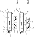
- FIG. 1 shows a conventional mixing device 10 with a gas guide section 12, which is designed essentially as a smooth tube.
- a gas guide section 12 On the left side of the gas routing section 12 it is connected to an exhaust system of an internal combustion engine. Exhaust gas G enters the gas routing section 12 on this side, which is indicated by two black arrows.
- An injector 14 is also arranged here, through which an aqueous urea solution is introduced into the exhaust gas stream G is introduced.
- a corresponding spray cone S is drawn in schematically.
- a swirl generator (not shown) is arranged upstream of the injector 14 and/or in the gas routing section 12 itself, through which the gas flow G was subjected to a swirl component in order to be able to better distribute the urea in the gas flow G.
- the twist component is represented schematically by a vortex D.
- a section 16 of the gas routing section is provided with a heating device 18 .
- the heating device 18 permits the active heating of the section 16 (also referred to as the heating section) in order to support the vaporization of the introduced urea.
- the urea is usually introduced into the gas flow G in a pulse width modulated manner. This means that the dosing takes place intermittently. Especially after a cold start, the exhaust gas and the mixing device are cold. As a result, the introduced urea is not completely vaporized but forms a film on the inner wall of the gas guide section 12 . Although the heating device 18 accelerates the reaching of the operating point, the formation of a film cannot be effectively avoided in many cases.
- In 1 shows that the film produced during the dosing process has migrated during the closing time of the injector 14. It is transported by the exhaust gas flow G to the outlet end of the gas routing section 12 . The consequence of this is that imperfect mixing is produced at the downstream end of the mixing device 10 .
- the concentration of urea is greater in areas close to the wall than in the central area, which is indicated schematically by a urea profile 20 .
- FIG 1 Which processes occur when a urea droplet 22 collides with the inner wall of the gas guide section 12 is in FIG 1 also shown schematically.
- a so-called "rebound” effect occurs.
- the urea droplet 22 strikes and rebounds against the inner wall of the section 12 at an angle, also being entrained due to the gas flow G in the direction of flow.
- the droplet 22 bursts into secondary droplets, which are also entrained by the gas flow G.
- the so-called "stick” effect also occurs when the droplet 22 collides with the inner wall of the section 12 .
- the droplet 22 remains on the wall after impact and, together with other droplets 22, forms a film F, which migrates under the action of the gas flow G (in 1 left to right).
- the comparatively rapid migration of the film F leads to an uneven distribution of the urea in the gas flow G. Furthermore, under unfavorable temperature conditions, the formation of deposits can occur.
- the mixing device 10-1 in 2 shown several elevations 24 are provided which protrude in the radial direction into the gas flow.
- the inner wall of the gas routing section 12 does not have a smooth surface, at least in the heating section 16, at least in sections, as is the case with conventional mixing devices (see Fig 1 ).
- the mixing device 10-1 provides the film F--figuratively speaking--through the elevations 24 with a resistance which the latter encounters during its migration has to overcome.
- the elevations 24 can be beads, for example, which are introduced into the gas routing section 12 . Their arrangement and number can be selected according to the respective requirements profile.
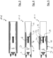
- the 3 shows a mixing device 10-2, which essentially corresponds to the mixing device 10-1.
- mixing device 10-1 essentially corresponds to the mixing device 10-1.
- mixing device 10-3 and 10-4 alternative mixing devices 10-3 and 10-4 are shown. This representation facilitates the comparison of the different embodiments.
- a narrower spray cone S is provided in the embodiment 10-3 according to 4 . Furthermore, a single elevation 24 is provided, which is designed essentially symmetrically and essentially the entire inner wall of the gas routing section 12 forms.
- the heating device 18 is arranged in the apex of the elevation 24 and in adjacent areas. The heating section 16 thus comprises a substantially central area of the gas routing section 12.
- the elevation 24 forms a nozzle-like constriction.
- the upstream portion of the constriction during operation of the injector which for the sake of simplicity in the Figures 2 to 9 not shown, wetted by urea.
- the produced film F then migrates into the throat and enters the heating section 16 where it is vaporized very efficiently.
- the gas flow G is accelerated by the constriction produced by the elevation 24, which can also contribute to improved mixing, in particular since the gas flow G has a swirl component D present.
- the elevation 24 is arranged in a downstream end area of the heating section 16 here. It is rotationally symmetrical in the present example.
- An upstream portion of the upstream flank 24a of the crest 24 is comparatively gently inclined. It goes into a steeper section.
- the upstream flank 24a of the elevation 24 transitions via a curved section 24s (apex section) into a substantially planar incline which is designed somewhat flatter than the steeper of the two sections of the upstream flank 24a of the elevation 24.
- the planar incline forms an upstream flank 24b of the elevation 24.
- the curved apex section 24s between the upstream flank 24a and the downstream flank 24b prevents the flow from being separated, which has a positive effect on the back pressure generated by the mixing device 10-4.
- the geometry of the elevations can be selected as required. It is entirely possible that individual aspects of those described above to combine geometries. The position and/or number of surveys can also be adjusted as required.
- Chamber 26 shows a chamber 26 of an exhaust system, which can also function as an acoustic chamber, for example.
- Chamber 26 includes a gas inlet portion 28 fluidly connected to an oxidation catalyst unit 30 (eg, DOC catalyst). Exhaust gas flowing out of the catalytic converter unit 30 is then fed to a particle filter 32 . The exhaust gas then flows through a deflection section 34 to the gas routing section 12 of a mixing device 10-5.
- the mixing device 10-5 can be designed, for example, according to one of the embodiments described above.
- the exhaust gas flows via a further deflection section 34 to an SCR catalytic converter unit 36 .
- Exhaust gas exiting from this chamber then enters the interior of the chamber 26.
- a corresponding gas outlet 38 is arranged and designed in such a way that the exhaust gas flows directly against the mixing device 10-5 at least in sections. This supports their heating, which is particularly advantageous when the internal combustion engine is started cold.
- the exhaust gas G emerging from the outlet 38 does not entirely flow directly to a gas outlet section 40 of the chamber 26 which is connected to other components of the exhaust system. Part of this exhaust gas is distributed in the chamber 26 and forms a secondary flow Gsek, which also applies heat to the catalytic converters 30, 32, 36 from the outside, so that they reach their operating point more quickly.
- the chamber 26 can also serve as an acoustic chamber and can include components for specifically influencing the noise emissions, in particular for damping them.
- FIG. 12 shows a mixing device 10-6 to which exhaust gas is supplied through the gas inlet section 28.
- the exhaust gas inlet section 28 is arranged approximately perpendicular to a longitudinal axis L of the mixing device 10-6.
- the inlet section 28 is also arranged in such a way that the exhaust gas flows in laterally offset to the longitudinal axis of the device 10-5.
- the gas routing section 12 of the device 10-6 comprises a mixing chamber 42 into which a dip tube 44 protrudes.
- a radial gap 46 into which the exhaust gas is introduced is provided between the inner wall of the mixing chamber 42 and the dip tube 44 . Due to the lateral offset of the introduction, the gas flow G in the gap 46 not only has an axial component, but also a twisting component.
- the exhaust gas flows around the outside of the dip tube 44 in a spiral shape before it reaches a metering area E, which is arranged on an end area of the mixing chamber opposite the gas inlet section 28 .
- the gas stream G subjected to the swirling action is here subjected to a spray cone S by means of an injector (not shown). Since the heating device is arranged in the dosing area E, the heating section 16 and the dosing area E essentially coincide.
- elevations are provided in the heating section 16 distributed in the circumferential direction and having an axial extension (not shown).
- the exhaust gas subjected to the swirl must therefore flow over these elevations. In this case, essentially the same effects occur as described at the outset on the basis of the 2 have been described.
- the exhaust gas treated with urea which also has a swirl component D, is forced into the dip tube 44 before it leaves the mixing device 10 - 6 via the gas outlet section 40 . It is then fed to the SCR catalytic converter unit 36 .
- the gas inlet section 28 can be designed as a so-called screw inlet, as a result of which the gas flow G is initially subjected to a twist.
- the gas flow G is now rectified by a perforated plate 48 or a functionally similar flow guide element, so that it essentially has only an axial flow component.
- the gas flow G is impinged with the urea solution.
- a flow deflection takes place here, as a result of which the exhaust gas flows in the opposite direction through the dip tube 44 out of the device 10 - 7 and to the SCR catalytic converter unit 36 .
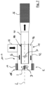
- the immersion tube 44 is provided with a heating device 18 .
- the heating section 16 of the device 10 - 7 is thus formed on the immersion tube 44 . At least one elevation is also provided in the region of the heating section 16 and preferably extends in the circumferential direction of the immersion tube 44 .
- the heating device 18 which comprises three heating coils 18s, is indicated in the upper half of the figure. Together they define the actively heated heating section 16.
- the gas routing section 12 Downstream of the spray cone S, the gas routing section 12 initially has a first elevation-free section 50-1. This is followed by a first elevation with an upstream flank 24a, which has a first, comparatively steep section and a second, more gently inclined section. The downstream flank 24b of the elevation 24-1 is also comparatively slightly inclined.
- a second elevation 24-2 follows, which ultimately leads to a real narrowing of the cross section. Namely, a second elevation-free portion 50-2 following the second elevation 24-2 has a smaller diameter than the elevation-free portion 50-1.
- a further elevation 24-3 is arranged downstream of the elevation-free section 50-2, which in turn has a comparatively steep upstream flank 24a and a comparatively flat downstream flank 24b.
- transition 24s between the two flanks 24a, 24b is elongated and curved, on the one hand to inhibit the migration of the urea film and on the other hand to achieve good evaporation of the urea with optimized flow dynamics at the same time.
- the elevation 24-3 is immediately followed by another elevation 24-4, which has a comparatively steep section and a section that is somewhat longer but flatter in the axial direction on its upstream flank 24a.
- the downstream flank 24b is comparatively steep and transitions into a widened outlet section 40 into which, for example, a tubular connection section of the exhaust system can be inserted.
- the elevations in the case of the device 10 - 8 are formed by varying the thickness of the material of the wall of the gas routing section 12 . Thicker sections are thermally more inert and store more thermal energy, so that particularly good evaporation of the introduced additive takes place here. It goes without saying that beads and elevations produced by forming can be combined from a solid material.
Landscapes
- Chemical & Material Sciences (AREA)
- Chemical Kinetics & Catalysis (AREA)
- Engineering & Computer Science (AREA)
- Health & Medical Sciences (AREA)
- Toxicology (AREA)
- Combustion & Propulsion (AREA)
- Mechanical Engineering (AREA)
- General Engineering & Computer Science (AREA)
- Dispersion Chemistry (AREA)
- Exhaust Gas After Treatment (AREA)
- Exhaust Gas Treatment By Means Of Catalyst (AREA)
- Accessories For Mixers (AREA)
Applications Claiming Priority (1)
| Application Number | Priority Date | Filing Date | Title |
|---|---|---|---|
| DE102021120423.2A DE102021120423A1 (de) | 2021-08-05 | 2021-08-05 | Mischvorrichtung |
Publications (2)
| Publication Number | Publication Date |
|---|---|
| EP4130446A1 true EP4130446A1 (fr) | 2023-02-08 |
| EP4130446B1 EP4130446B1 (fr) | 2024-08-14 |
Family
ID=82404027
Family Applications (1)
| Application Number | Title | Priority Date | Filing Date |
|---|---|---|---|
| EP22181541.8A Active EP4130446B1 (fr) | 2021-08-05 | 2022-06-28 | Dispositif de mélange |
Country Status (6)
| Country | Link |
|---|---|
| US (1) | US11814999B2 (fr) |
| EP (1) | EP4130446B1 (fr) |
| JP (1) | JP2023024308A (fr) |
| CN (1) | CN115888381A (fr) |
| DE (1) | DE102021120423A1 (fr) |
| ES (1) | ES2993607T3 (fr) |
Families Citing this family (2)
| Publication number | Priority date | Publication date | Assignee | Title |
|---|---|---|---|---|
| JP7234880B2 (ja) * | 2019-09-20 | 2023-03-08 | 株式会社三洋物産 | 遊技機 |
| CN116328643B (zh) * | 2023-02-23 | 2026-04-24 | 安徽晋煤中能化工股份有限公司 | 一种车用尿素制备用混合装置 |
Citations (7)
| Publication number | Priority date | Publication date | Assignee | Title |
|---|---|---|---|---|
| WO2006003868A1 (fr) * | 2004-07-02 | 2006-01-12 | Nissan Diesel Motor Co., Ltd. | Dispositif de purification d’échappement |
| EP2090761A1 (fr) * | 2008-02-16 | 2009-08-19 | Pierburg GmbH | Système de traitement des gaz d'échappement pour un moteur à combustion interne |
| EP2268904B1 (fr) * | 2008-04-16 | 2011-11-09 | Robert Bosch GmbH | Dispositif d´amenée d´un réactif dans un tuyau d´échappement d´un système d´ échappement d´un véhicule automobile |
| WO2017198292A1 (fr) * | 2016-05-18 | 2017-11-23 | Volvo Truck Corporation | Système de traitement des gaz d'échappement à chauffage inductif |
| EP3406873A1 (fr) * | 2017-05-22 | 2018-11-28 | Volkswagen Aktiengesellschaft | Système de traitement de gaz d'échappement pour un moteur à combustion interne |
| US20190112962A1 (en) * | 2017-10-18 | 2019-04-18 | Eberspächer Exhaust Technology GmbH & Co. KG | Mixing device |
| US10337381B2 (en) * | 2016-03-23 | 2019-07-02 | Volvo Car Corporation | Exhaust gas aftertreatment device for an internal combustion engine |
Family Cites Families (6)
| Publication number | Priority date | Publication date | Assignee | Title |
|---|---|---|---|---|
| DE1253955B (de) * | 1965-05-26 | 1967-11-09 | Fitterer & Sohn Arno | Vorrichtung zum Entgiften von Abgasen, insbesondere aus Verbrennungsmotoren |
| DE102004020138B4 (de) | 2004-04-24 | 2007-02-08 | Daimlerchrysler Ag | Reduktionsmittelzugabesystem |
| KR20110063137A (ko) * | 2009-12-04 | 2011-06-10 | 현대자동차주식회사 | 차량의 배기 시스템용 선택적 촉매 환원 장치 |
| DE102011117139A1 (de) * | 2011-10-28 | 2013-05-02 | Emitec Gesellschaft Für Emissionstechnologie Mbh | Mischeranordnung zur Reduktionsmittelaufbereitung |
| DE102017124032A1 (de) * | 2017-10-16 | 2019-04-18 | Eberspächer Exhaust Technology GmbH & Co. KG | Abgas/Reaktionsmittel-Mischbaugruppe |
| US11352927B2 (en) * | 2020-07-21 | 2022-06-07 | Paccar Inc | Control of selective catalytic reduction in heavy-duty motor vehicle engines |
-
2021
- 2021-08-05 DE DE102021120423.2A patent/DE102021120423A1/de active Pending
-
2022
- 2022-06-28 ES ES22181541T patent/ES2993607T3/es active Active
- 2022-06-28 EP EP22181541.8A patent/EP4130446B1/fr active Active
- 2022-07-15 JP JP2022113770A patent/JP2023024308A/ja active Pending
- 2022-07-25 CN CN202210874701.2A patent/CN115888381A/zh active Pending
- 2022-07-29 US US17/876,851 patent/US11814999B2/en active Active
Patent Citations (7)
| Publication number | Priority date | Publication date | Assignee | Title |
|---|---|---|---|---|
| WO2006003868A1 (fr) * | 2004-07-02 | 2006-01-12 | Nissan Diesel Motor Co., Ltd. | Dispositif de purification d’échappement |
| EP2090761A1 (fr) * | 2008-02-16 | 2009-08-19 | Pierburg GmbH | Système de traitement des gaz d'échappement pour un moteur à combustion interne |
| EP2268904B1 (fr) * | 2008-04-16 | 2011-11-09 | Robert Bosch GmbH | Dispositif d´amenée d´un réactif dans un tuyau d´échappement d´un système d´ échappement d´un véhicule automobile |
| US10337381B2 (en) * | 2016-03-23 | 2019-07-02 | Volvo Car Corporation | Exhaust gas aftertreatment device for an internal combustion engine |
| WO2017198292A1 (fr) * | 2016-05-18 | 2017-11-23 | Volvo Truck Corporation | Système de traitement des gaz d'échappement à chauffage inductif |
| EP3406873A1 (fr) * | 2017-05-22 | 2018-11-28 | Volkswagen Aktiengesellschaft | Système de traitement de gaz d'échappement pour un moteur à combustion interne |
| US20190112962A1 (en) * | 2017-10-18 | 2019-04-18 | Eberspächer Exhaust Technology GmbH & Co. KG | Mixing device |
Also Published As
| Publication number | Publication date |
|---|---|
| DE102021120423A1 (de) | 2023-02-09 |
| JP2023024308A (ja) | 2023-02-16 |
| US11814999B2 (en) | 2023-11-14 |
| US20230037405A1 (en) | 2023-02-09 |
| EP4130446B1 (fr) | 2024-08-14 |
| CN115888381A (zh) | 2023-04-04 |
| ES2993607T3 (en) | 2025-01-02 |
Similar Documents
| Publication | Publication Date | Title |
|---|---|---|
| EP2700442B1 (fr) | Installation de gaz d'échappement avec dispositif de mélange et/ou d'évaporation | |
| EP1714011B1 (fr) | Procede et dispositif de traitement posterieur de gaz d'echappement d'un moteur a combustion interne | |
| EP2921220B1 (fr) | Mélangeur pour une installation de gaz d'échappement | |
| EP2570178B1 (fr) | Dispositif de mélange | |
| WO2013010700A1 (fr) | Agencement permettant d'introduire un additif dans un flux de gaz | |
| EP3443209B1 (fr) | Dispositif de post-traitement des gaz d'échappement doté d'un catalyseur et d'un dispositif de mélange | |
| EP1890016A2 (fr) | Procédé destiné à l'ajout d'au moins un additif à un flux de gaz d'échappement et dispositif destiné à la préparation d'un flux de gaz d'échappement d'un moteur à combustion interne | |
| DE102009053950A1 (de) | Vorrichtung zur Nachbehandlung von Abgasen von Brennkraftmaschinen | |
| WO2013127955A1 (fr) | Dispositif d'épuration d'effluents gazeux | |
| EP1969213A1 (fr) | Composant destine a etre monte dans le parcours des gaz d'echappement d'un moteur a combustion interne | |
| DE102008008563A1 (de) | Dosiervorrichtung zur Schadstoffverminderung in Abgasen | |
| EP3857034A1 (fr) | Dispositif permettant d'ajouter un agent de réduction liquide au gaz d'échappement d'un moteur à combustion interne et véhicule automobile | |
| EP4130446B1 (fr) | Dispositif de mélange | |
| WO2016062395A1 (fr) | Système de post-traitement des gaz d'échappement destiné à un moteur à combustion interne, en particulier d'un véhicule à moteur | |
| DE102013211662A1 (de) | Mischereinrichtung | |
| DE19963394A1 (de) | Vorrichtung zur Aerosolbildung und Vorrichtung zur Nachbehandlung von Abgasen | |
| DE102016014966B4 (de) | Abgasnachbehandlungseinrichtung für einen Kraftwagen | |
| DE102012014528A1 (de) | Mehrstufiger Plattenmischer | |
| EP3470641B1 (fr) | Système d'échappement | |
| EP3752721B1 (fr) | Dispositif de retraitement de gaz d'échappement permettant l'introduction dosée d'un agent de retraitement de gaz d'échappement | |
| EP3050615A1 (fr) | Unité d'écoulement, installation de nettoyage des gaz d'échappement et procédé pour une installation de nettoyage des gaz d'échappement | |
| WO2020108991A1 (fr) | Système compact de post-traitement des gaz d'échappement | |
| EP4453393B1 (fr) | Mélangeur pour un système de post-traitement des gaz d'échappement d'un véhicule automobile | |
| EP3663551B1 (fr) | Dispositif pour introduire et distribuer un additif fluide dans un flux de gaz d'échappement | |
| DE102015209165B4 (de) | Abgasbehandlungseinrichtung für eine Brennkraftmaschine |
Legal Events
| Date | Code | Title | Description |
|---|---|---|---|
| PUAI | Public reference made under article 153(3) epc to a published international application that has entered the european phase |
Free format text: ORIGINAL CODE: 0009012 |
|
| STAA | Information on the status of an ep patent application or granted ep patent |
Free format text: STATUS: THE APPLICATION HAS BEEN PUBLISHED |
|
| AK | Designated contracting states |
Kind code of ref document: A1 Designated state(s): AL AT BE BG CH CY CZ DE DK EE ES FI FR GB GR HR HU IE IS IT LI LT LU LV MC MK MT NL NO PL PT RO RS SE SI SK SM TR |
|
| STAA | Information on the status of an ep patent application or granted ep patent |
Free format text: STATUS: REQUEST FOR EXAMINATION WAS MADE |
|
| 17P | Request for examination filed |
Effective date: 20230726 |
|
| RBV | Designated contracting states (corrected) |
Designated state(s): AL AT BE BG CH CY CZ DE DK EE ES FI FR GB GR HR HU IE IS IT LI LT LU LV MC MK MT NL NO PL PT RO RS SE SI SK SM TR |
|
| GRAP | Despatch of communication of intention to grant a patent |
Free format text: ORIGINAL CODE: EPIDOSNIGR1 |
|
| STAA | Information on the status of an ep patent application or granted ep patent |
Free format text: STATUS: GRANT OF PATENT IS INTENDED |
|
| RIC1 | Information provided on ipc code assigned before grant |
Ipc: B01F 35/92 20220101ALI20240403BHEP Ipc: B01F 35/90 20220101ALI20240403BHEP Ipc: B01F 25/433 20220101ALI20240403BHEP Ipc: B01F 23/213 20220101ALI20240403BHEP Ipc: F01N 3/28 20060101ALI20240403BHEP Ipc: F01N 3/20 20060101AFI20240403BHEP |
|
| INTG | Intention to grant announced |
Effective date: 20240419 |
|
| GRAS | Grant fee paid |
Free format text: ORIGINAL CODE: EPIDOSNIGR3 |
|
| GRAA | (expected) grant |
Free format text: ORIGINAL CODE: 0009210 |
|
| STAA | Information on the status of an ep patent application or granted ep patent |
Free format text: STATUS: THE PATENT HAS BEEN GRANTED |
|
| AK | Designated contracting states |
Kind code of ref document: B1 Designated state(s): AL AT BE BG CH CY CZ DE DK EE ES FI FR GB GR HR HU IE IS IT LI LT LU LV MC MK MT NL NO PL PT RO RS SE SI SK SM TR |
|
| REG | Reference to a national code |
Ref country code: GB Ref legal event code: FG4D Free format text: NOT ENGLISH |
|
| REG | Reference to a national code |
Ref country code: CH Ref legal event code: EP |
|
| REG | Reference to a national code |
Ref country code: DE Ref legal event code: R096 Ref document number: 502022001444 Country of ref document: DE |
|
| REG | Reference to a national code |
Ref country code: IE Ref legal event code: FG4D Free format text: LANGUAGE OF EP DOCUMENT: GERMAN |
|
| REG | Reference to a national code |
Ref country code: LT Ref legal event code: MG9D |
|
| REG | Reference to a national code |
Ref country code: NL Ref legal event code: MP Effective date: 20240814 |
|
| REG | Reference to a national code |
Ref country code: ES Ref legal event code: FG2A Ref document number: 2993607 Country of ref document: ES Kind code of ref document: T3 Effective date: 20250102 |
|
| PG25 | Lapsed in a contracting state [announced via postgrant information from national office to epo] |
Ref country code: NO Free format text: LAPSE BECAUSE OF FAILURE TO SUBMIT A TRANSLATION OF THE DESCRIPTION OR TO PAY THE FEE WITHIN THE PRESCRIBED TIME-LIMIT Effective date: 20241114 |
|
| PG25 | Lapsed in a contracting state [announced via postgrant information from national office to epo] |
Ref country code: NL Free format text: LAPSE BECAUSE OF FAILURE TO SUBMIT A TRANSLATION OF THE DESCRIPTION OR TO PAY THE FEE WITHIN THE PRESCRIBED TIME-LIMIT Effective date: 20240814 Ref country code: FI Free format text: LAPSE BECAUSE OF FAILURE TO SUBMIT A TRANSLATION OF THE DESCRIPTION OR TO PAY THE FEE WITHIN THE PRESCRIBED TIME-LIMIT Effective date: 20240814 Ref country code: PL Free format text: LAPSE BECAUSE OF FAILURE TO SUBMIT A TRANSLATION OF THE DESCRIPTION OR TO PAY THE FEE WITHIN THE PRESCRIBED TIME-LIMIT Effective date: 20240814 Ref country code: GR Free format text: LAPSE BECAUSE OF FAILURE TO SUBMIT A TRANSLATION OF THE DESCRIPTION OR TO PAY THE FEE WITHIN THE PRESCRIBED TIME-LIMIT Effective date: 20241115 Ref country code: PT Free format text: LAPSE BECAUSE OF FAILURE TO SUBMIT A TRANSLATION OF THE DESCRIPTION OR TO PAY THE FEE WITHIN THE PRESCRIBED TIME-LIMIT Effective date: 20241216 |
|
| PG25 | Lapsed in a contracting state [announced via postgrant information from national office to epo] |
Ref country code: BG Free format text: LAPSE BECAUSE OF FAILURE TO SUBMIT A TRANSLATION OF THE DESCRIPTION OR TO PAY THE FEE WITHIN THE PRESCRIBED TIME-LIMIT Effective date: 20240814 |
|
| PG25 | Lapsed in a contracting state [announced via postgrant information from national office to epo] |
Ref country code: LV Free format text: LAPSE BECAUSE OF FAILURE TO SUBMIT A TRANSLATION OF THE DESCRIPTION OR TO PAY THE FEE WITHIN THE PRESCRIBED TIME-LIMIT Effective date: 20240814 |
|
| PG25 | Lapsed in a contracting state [announced via postgrant information from national office to epo] |
Ref country code: IS Free format text: LAPSE BECAUSE OF FAILURE TO SUBMIT A TRANSLATION OF THE DESCRIPTION OR TO PAY THE FEE WITHIN THE PRESCRIBED TIME-LIMIT Effective date: 20241214 |
|
| PG25 | Lapsed in a contracting state [announced via postgrant information from national office to epo] |
Ref country code: HR Free format text: LAPSE BECAUSE OF FAILURE TO SUBMIT A TRANSLATION OF THE DESCRIPTION OR TO PAY THE FEE WITHIN THE PRESCRIBED TIME-LIMIT Effective date: 20240814 |
|
| PG25 | Lapsed in a contracting state [announced via postgrant information from national office to epo] |
Ref country code: RS Free format text: LAPSE BECAUSE OF FAILURE TO SUBMIT A TRANSLATION OF THE DESCRIPTION OR TO PAY THE FEE WITHIN THE PRESCRIBED TIME-LIMIT Effective date: 20241114 |
|
| PG25 | Lapsed in a contracting state [announced via postgrant information from national office to epo] |
Ref country code: RS Free format text: LAPSE BECAUSE OF FAILURE TO SUBMIT A TRANSLATION OF THE DESCRIPTION OR TO PAY THE FEE WITHIN THE PRESCRIBED TIME-LIMIT Effective date: 20241114 Ref country code: PT Free format text: LAPSE BECAUSE OF FAILURE TO SUBMIT A TRANSLATION OF THE DESCRIPTION OR TO PAY THE FEE WITHIN THE PRESCRIBED TIME-LIMIT Effective date: 20241216 Ref country code: PL Free format text: LAPSE BECAUSE OF FAILURE TO SUBMIT A TRANSLATION OF THE DESCRIPTION OR TO PAY THE FEE WITHIN THE PRESCRIBED TIME-LIMIT Effective date: 20240814 Ref country code: NO Free format text: LAPSE BECAUSE OF FAILURE TO SUBMIT A TRANSLATION OF THE DESCRIPTION OR TO PAY THE FEE WITHIN THE PRESCRIBED TIME-LIMIT Effective date: 20241114 Ref country code: NL Free format text: LAPSE BECAUSE OF FAILURE TO SUBMIT A TRANSLATION OF THE DESCRIPTION OR TO PAY THE FEE WITHIN THE PRESCRIBED TIME-LIMIT Effective date: 20240814 Ref country code: LV Free format text: LAPSE BECAUSE OF FAILURE TO SUBMIT A TRANSLATION OF THE DESCRIPTION OR TO PAY THE FEE WITHIN THE PRESCRIBED TIME-LIMIT Effective date: 20240814 Ref country code: IS Free format text: LAPSE BECAUSE OF FAILURE TO SUBMIT A TRANSLATION OF THE DESCRIPTION OR TO PAY THE FEE WITHIN THE PRESCRIBED TIME-LIMIT Effective date: 20241214 Ref country code: HR Free format text: LAPSE BECAUSE OF FAILURE TO SUBMIT A TRANSLATION OF THE DESCRIPTION OR TO PAY THE FEE WITHIN THE PRESCRIBED TIME-LIMIT Effective date: 20240814 Ref country code: GR Free format text: LAPSE BECAUSE OF FAILURE TO SUBMIT A TRANSLATION OF THE DESCRIPTION OR TO PAY THE FEE WITHIN THE PRESCRIBED TIME-LIMIT Effective date: 20241115 Ref country code: FI Free format text: LAPSE BECAUSE OF FAILURE TO SUBMIT A TRANSLATION OF THE DESCRIPTION OR TO PAY THE FEE WITHIN THE PRESCRIBED TIME-LIMIT Effective date: 20240814 Ref country code: BG Free format text: LAPSE BECAUSE OF FAILURE TO SUBMIT A TRANSLATION OF THE DESCRIPTION OR TO PAY THE FEE WITHIN THE PRESCRIBED TIME-LIMIT Effective date: 20240814 |
|
| PG25 | Lapsed in a contracting state [announced via postgrant information from national office to epo] |
Ref country code: DK Free format text: LAPSE BECAUSE OF FAILURE TO SUBMIT A TRANSLATION OF THE DESCRIPTION OR TO PAY THE FEE WITHIN THE PRESCRIBED TIME-LIMIT Effective date: 20240814 Ref country code: SM Free format text: LAPSE BECAUSE OF FAILURE TO SUBMIT A TRANSLATION OF THE DESCRIPTION OR TO PAY THE FEE WITHIN THE PRESCRIBED TIME-LIMIT Effective date: 20240814 Ref country code: RO Free format text: LAPSE BECAUSE OF FAILURE TO SUBMIT A TRANSLATION OF THE DESCRIPTION OR TO PAY THE FEE WITHIN THE PRESCRIBED TIME-LIMIT Effective date: 20240814 |
|
| PG25 | Lapsed in a contracting state [announced via postgrant information from national office to epo] |
Ref country code: EE Free format text: LAPSE BECAUSE OF FAILURE TO SUBMIT A TRANSLATION OF THE DESCRIPTION OR TO PAY THE FEE WITHIN THE PRESCRIBED TIME-LIMIT Effective date: 20240814 |
|
| PG25 | Lapsed in a contracting state [announced via postgrant information from national office to epo] |
Ref country code: CZ Free format text: LAPSE BECAUSE OF FAILURE TO SUBMIT A TRANSLATION OF THE DESCRIPTION OR TO PAY THE FEE WITHIN THE PRESCRIBED TIME-LIMIT Effective date: 20240814 |
|
| PG25 | Lapsed in a contracting state [announced via postgrant information from national office to epo] |
Ref country code: SK Free format text: LAPSE BECAUSE OF FAILURE TO SUBMIT A TRANSLATION OF THE DESCRIPTION OR TO PAY THE FEE WITHIN THE PRESCRIBED TIME-LIMIT Effective date: 20240814 |
|
| REG | Reference to a national code |
Ref country code: DE Ref legal event code: R097 Ref document number: 502022001444 Country of ref document: DE |
|
| PLBE | No opposition filed within time limit |
Free format text: ORIGINAL CODE: 0009261 |
|
| STAA | Information on the status of an ep patent application or granted ep patent |
Free format text: STATUS: NO OPPOSITION FILED WITHIN TIME LIMIT |
|
| PGFP | Annual fee paid to national office [announced via postgrant information from national office to epo] |
Ref country code: FR Payment date: 20250627 Year of fee payment: 4 |
|
| 26N | No opposition filed |
Effective date: 20250515 |
|
| PGFP | Annual fee paid to national office [announced via postgrant information from national office to epo] |
Ref country code: AT Payment date: 20250721 Year of fee payment: 4 |
|
| PG25 | Lapsed in a contracting state [announced via postgrant information from national office to epo] |
Ref country code: SE Free format text: LAPSE BECAUSE OF FAILURE TO SUBMIT A TRANSLATION OF THE DESCRIPTION OR TO PAY THE FEE WITHIN THE PRESCRIBED TIME-LIMIT Effective date: 20240814 |
|
| PGFP | Annual fee paid to national office [announced via postgrant information from national office to epo] |
Ref country code: ES Payment date: 20250731 Year of fee payment: 4 |
|
| PGFP | Annual fee paid to national office [announced via postgrant information from national office to epo] |
Ref country code: DE Payment date: 20250827 Year of fee payment: 4 |
|
| PGFP | Annual fee paid to national office [announced via postgrant information from national office to epo] |
Ref country code: IT Payment date: 20250630 Year of fee payment: 4 |
|
| REG | Reference to a national code |
Ref country code: CH Ref legal event code: H13 Free format text: ST27 STATUS EVENT CODE: U-0-0-H10-H13 (AS PROVIDED BY THE NATIONAL OFFICE) Effective date: 20260127 |
|
| PG25 | Lapsed in a contracting state [announced via postgrant information from national office to epo] |
Ref country code: MC Free format text: LAPSE BECAUSE OF FAILURE TO SUBMIT A TRANSLATION OF THE DESCRIPTION OR TO PAY THE FEE WITHIN THE PRESCRIBED TIME-LIMIT Effective date: 20240814 |
|
| PG25 | Lapsed in a contracting state [announced via postgrant information from national office to epo] |
Ref country code: LU Free format text: LAPSE BECAUSE OF NON-PAYMENT OF DUE FEES Effective date: 20250628 |
|
| REG | Reference to a national code |
Ref country code: BE Ref legal event code: MM Effective date: 20250630 |
|
| PG25 | Lapsed in a contracting state [announced via postgrant information from national office to epo] |
Ref country code: IE Free format text: LAPSE BECAUSE OF NON-PAYMENT OF DUE FEES Effective date: 20250628 |
|
| PG25 | Lapsed in a contracting state [announced via postgrant information from national office to epo] |
Ref country code: BE Free format text: LAPSE BECAUSE OF NON-PAYMENT OF DUE FEES Effective date: 20250630 |
|
| PG25 | Lapsed in a contracting state [announced via postgrant information from national office to epo] |
Ref country code: CH Free format text: LAPSE BECAUSE OF NON-PAYMENT OF DUE FEES Effective date: 20250630 |