EP4130557A1 - Optische linse, optische linsengruppe, fahrzeuglampensystem und fahrzeug - Google Patents
Optische linse, optische linsengruppe, fahrzeuglampensystem und fahrzeug Download PDFInfo
- Publication number
- EP4130557A1 EP4130557A1 EP21796757.9A EP21796757A EP4130557A1 EP 4130557 A1 EP4130557 A1 EP 4130557A1 EP 21796757 A EP21796757 A EP 21796757A EP 4130557 A1 EP4130557 A1 EP 4130557A1
- Authority
- EP
- European Patent Office
- Prior art keywords
- directional
- optical lens
- lens group
- alignment surface
- collimating
- Prior art date
- Legal status (The legal status is an assumption and is not a legal conclusion. Google has not performed a legal analysis and makes no representation as to the accuracy of the status listed.)
- Pending
Links
Images





Classifications
-
- F—MECHANICAL ENGINEERING; LIGHTING; HEATING; WEAPONS; BLASTING
- F21—LIGHTING
- F21S—NON-PORTABLE LIGHTING DEVICES; SYSTEMS THEREOF; VEHICLE LIGHTING DEVICES SPECIALLY ADAPTED FOR VEHICLE EXTERIORS
- F21S41/00—Illuminating devices specially adapted for vehicle exteriors, e.g. headlamps
- F21S41/20—Illuminating devices specially adapted for vehicle exteriors, e.g. headlamps characterised by refractors, transparent cover plates, light guides or filters
- F21S41/25—Projection lenses
- F21S41/27—Thick lenses
-
- F—MECHANICAL ENGINEERING; LIGHTING; HEATING; WEAPONS; BLASTING
- F21—LIGHTING
- F21S—NON-PORTABLE LIGHTING DEVICES; SYSTEMS THEREOF; VEHICLE LIGHTING DEVICES SPECIALLY ADAPTED FOR VEHICLE EXTERIORS
- F21S41/00—Illuminating devices specially adapted for vehicle exteriors, e.g. headlamps
- F21S41/20—Illuminating devices specially adapted for vehicle exteriors, e.g. headlamps characterised by refractors, transparent cover plates, light guides or filters
- F21S41/25—Projection lenses
-
- F—MECHANICAL ENGINEERING; LIGHTING; HEATING; WEAPONS; BLASTING
- F21—LIGHTING
- F21S—NON-PORTABLE LIGHTING DEVICES; SYSTEMS THEREOF; VEHICLE LIGHTING DEVICES SPECIALLY ADAPTED FOR VEHICLE EXTERIORS
- F21S41/00—Illuminating devices specially adapted for vehicle exteriors, e.g. headlamps
- F21S41/20—Illuminating devices specially adapted for vehicle exteriors, e.g. headlamps characterised by refractors, transparent cover plates, light guides or filters
- F21S41/25—Projection lenses
- F21S41/255—Lenses with a front view of circular or truncated circular outline
-
- F—MECHANICAL ENGINEERING; LIGHTING; HEATING; WEAPONS; BLASTING
- F21—LIGHTING
- F21S—NON-PORTABLE LIGHTING DEVICES; SYSTEMS THEREOF; VEHICLE LIGHTING DEVICES SPECIALLY ADAPTED FOR VEHICLE EXTERIORS
- F21S41/00—Illuminating devices specially adapted for vehicle exteriors, e.g. headlamps
- F21S41/20—Illuminating devices specially adapted for vehicle exteriors, e.g. headlamps characterised by refractors, transparent cover plates, light guides or filters
- F21S41/25—Projection lenses
- F21S41/265—Composite lenses; Lenses with a patch-like shape
-
- F—MECHANICAL ENGINEERING; LIGHTING; HEATING; WEAPONS; BLASTING
- F21—LIGHTING
- F21S—NON-PORTABLE LIGHTING DEVICES; SYSTEMS THEREOF; VEHICLE LIGHTING DEVICES SPECIALLY ADAPTED FOR VEHICLE EXTERIORS
- F21S41/00—Illuminating devices specially adapted for vehicle exteriors, e.g. headlamps
- F21S41/20—Illuminating devices specially adapted for vehicle exteriors, e.g. headlamps characterised by refractors, transparent cover plates, light guides or filters
- F21S41/25—Projection lenses
- F21S41/275—Lens surfaces, e.g. coatings or surface structures
-
- F—MECHANICAL ENGINEERING; LIGHTING; HEATING; WEAPONS; BLASTING
- F21—LIGHTING
- F21S—NON-PORTABLE LIGHTING DEVICES; SYSTEMS THEREOF; VEHICLE LIGHTING DEVICES SPECIALLY ADAPTED FOR VEHICLE EXTERIORS
- F21S41/00—Illuminating devices specially adapted for vehicle exteriors, e.g. headlamps
- F21S41/20—Illuminating devices specially adapted for vehicle exteriors, e.g. headlamps characterised by refractors, transparent cover plates, light guides or filters
- F21S41/285—Refractors, transparent cover plates, light guides or filters not provided in groups F21S41/24 - F21S41/2805
-
- F—MECHANICAL ENGINEERING; LIGHTING; HEATING; WEAPONS; BLASTING
- F21—LIGHTING
- F21S—NON-PORTABLE LIGHTING DEVICES; SYSTEMS THEREOF; VEHICLE LIGHTING DEVICES SPECIALLY ADAPTED FOR VEHICLE EXTERIORS
- F21S41/00—Illuminating devices specially adapted for vehicle exteriors, e.g. headlamps
- F21S41/30—Illuminating devices specially adapted for vehicle exteriors, e.g. headlamps characterised by reflectors
- F21S41/32—Optical layout thereof
- F21S41/321—Optical layout thereof the reflector being a surface of revolution or a planar surface, e.g. truncated
-
- F—MECHANICAL ENGINEERING; LIGHTING; HEATING; WEAPONS; BLASTING
- F21—LIGHTING
- F21S—NON-PORTABLE LIGHTING DEVICES; SYSTEMS THEREOF; VEHICLE LIGHTING DEVICES SPECIALLY ADAPTED FOR VEHICLE EXTERIORS
- F21S41/00—Illuminating devices specially adapted for vehicle exteriors, e.g. headlamps
- F21S41/30—Illuminating devices specially adapted for vehicle exteriors, e.g. headlamps characterised by reflectors
- F21S41/32—Optical layout thereof
-
- F—MECHANICAL ENGINEERING; LIGHTING; HEATING; WEAPONS; BLASTING
- F21—LIGHTING
- F21W—INDEXING SCHEME ASSOCIATED WITH SUBCLASSES F21K, F21L, F21S and F21V, RELATING TO USES OR APPLICATIONS OF LIGHTING DEVICES OR SYSTEMS
- F21W2102/00—Exterior vehicle lighting devices for illuminating purposes
-
- F—MECHANICAL ENGINEERING; LIGHTING; HEATING; WEAPONS; BLASTING
- F21—LIGHTING
- F21W—INDEXING SCHEME ASSOCIATED WITH SUBCLASSES F21K, F21L, F21S and F21V, RELATING TO USES OR APPLICATIONS OF LIGHTING DEVICES OR SYSTEMS
- F21W2102/00—Exterior vehicle lighting devices for illuminating purposes
- F21W2102/10—Arrangement or contour of the emitted light
- F21W2102/13—Arrangement or contour of the emitted light for high-beam region or low-beam region
- F21W2102/135—Arrangement or contour of the emitted light for high-beam region or low-beam region the light having cut-off lines, i.e. clear borderlines between emitted regions and dark regions
Definitions
- the present application relates to vehicle optical elements, in particular, to an optical lens. Furthermore, it relates to an optical lens group, a vehicle lamp system having the optical lens or the optical lens group, and a vehicle having the vehicle lamp system.
- the vehicle lamps refer to lamps on a vehicle, which are lighting tools for vehicles driving on road at night, and also prompt tools for issuing various driving signals of a vehicle.
- the vehicle lamps play a very important role in terms of ensuring the safe driving of vehicles.
- society and economy the automobile industry also develops, and with continuous development of automobile lighting technology, more requirements are proposed for functions of vehicle lamps.
- collimating optical elements are usually provided to obtain approximately parallel outgoing light, for example, a hyperboloid collimating lens is provided, the curved surface on which is a revolving surface based on the optical axis of the lens, with the imaging characteristics being isotropic.
- the vehicle lamp lighting system based on the above-mentioned collimating lens needs to form the fundamental light shape with a certain width through an additional optical system, and the light shape is then imaged to the road surface through the collimating lens, which makes the structure relatively complex.
- a technical problem to be solved by the present application is to provide an optical lens, which can meet the requirement that the light shape of lighting of the vehicle lamp is anisotropy to form an asymmetric light shape.
- a further technical problem to be solved by the present application is to provide an optical lens group, which can meet the requirement that the light shape of the lighting of the vehicle lamp is anisotropy, so as to form an asymmetric light shape.
- a further technical problem to be solved by the present application is to provide a vehicle lamp system, which can reduce the structural size of the vehicle lamp.
- a technical problem to be solved by the present application is to provide a vehicle with better lighting effect.
- An optical lens comprising a light incident portion and a light emergent portion, wherein the light incident portion is formed with a first single-directional alignment surface, and the light emergent portion is formed with a second single-directional alignment surface, an alignment direction of the first single-directional alignment surface and an alignment direction of the second single-directional alignment surface are perpendicular to each other, and the first single-directional alignment surface and the second single-directional alignment surface jointly form a focal point or focus area of the optical lens.
- each of the first single-directional alignment surface and the second single-directional alignment surface is a curved surface formed by stretching an collimating curve along a normal direction of a plane where the collimating curve is located.
- each of the first single-directional alignment surface and the second single-directional alignment surface is a cylindrical or quasi-cylindrical surface.
- each of the first single-directional alignment surface and the second single-directional alignment surface is a circular cylindrical surface.
- each of the first single-directional alignment surface and the second single-directional alignment surface is a stepped Fresnel cylindrical surface.
- one of the first single-directional alignment surface and the second single-directional alignment surface is a cylindrical surface, and the other is a stepped Fresnel cylindrical surface.
- one of an alignment direction of the first single-directional alignment surface and an alignment direction of the second single-directional alignment surface is a vertical direction, and the other is a horizontal direction.
- first single-directional alignment surface and the second single-directional alignment surface cooperate with each other to make focal lengths on both sides of the optical lens different, such that an asymmetric light shape can be formed.
- the present application also provides an optical lens group, comprising a first single-directional collimating lens group and a second single-directional collimating lens group, wherein the first single-directional collimating lens group and the second single-directional collimating lens group jointly form a focal point or a focus area of the optical lens group, and an alignment direction of the first single-directional collimating lens group and an alignment direction of the second single-directional collimating lens group are perpendicular to each other.
- each of the first single-directional collimating lens group and the second single-directional collimating lens group is composed of at least one single-directional collimating lens.
- one of an incident surface and an emergent surface of the single-directional collimating lens is a single-directional collimating curved surface, or both of them are single-direction collimating curved surfaces with the same collimating direction.
- the first single-directional collimating lens group and the second single-directional collimating lens group are connected by a side wall.
- the present application also provides a vehicle lamp system, comprising the optical lens or the optical lens group according to any of the technical solutions mentioned above.
- it further comprises a light source, wherein the light source is arranged at a focal point or a focus area of the optical lens or the optical lens group; or, it further comprises a light source and a primary optical element, wherein the primary optical element is arranged to be able to converge light emitted by the light source to the focal point or the focus area of the optical lens or the optical lens group and introduce it into the optical lens or the optical lens group.
- the present application also provides a vehicle, comprising the vehicle lamp system according to any of the technical solutions mentioned above.
- the optical lens of the present application includes a first single-directional alignment surface and a second single-directional alignment surface
- the first single-directional alignment surface has the characteristics of single-directional collimation of the light. For example, there is no refraction or at most only very weak refraction in one section direction of the first single-directional alignment surface (the cutting curve is almost a straight line). Meanwhile, it has the greatest refraction effect in the direction perpendicular to this section, that is, the alignment direction of the first single-directional alignment surface is single-directional.
- the second single-directional alignment surface also has the same characteristics of single-directional collimation of the light, that is, the alignment direction of the second single-directional alignment surface is also single-directional.
- the alignment direction of the first single-directional alignment surface and the alignment direction of the second single-directional alignment surface are perpendicular to each other, so that an asymmetric light shape can be formed.
- the asymmetric light shape mainly refers to that when a square light-emitting surface is imaged, the light shape presents a rectangle, rather than the isotropic approximately square light shape formed by the existing collimating lens.
- the optical lens has a focal point or a focal area. When the light source is placed near the focal point or inside the focal area, a better optical effect can be obtained, and a higher utilization rate of light energy can be achieved.
- the present application can also realize the same function as the above-mentioned optical lens in the form of an optical lens group.
- first and second are only used for the purpose of description, and cannot be understood as indicating or implying importance of relativity or indicating the number of technical features indicated.
- a feature defined by “first” and “second” may expressly or implicitly includes one or more of the stated features.
- the terms “providing” and “arranging” should be understood in a broad sense, for example, it may be a fixed connection, a detachable connection, or an integral connection; it may be a direct connection or an indirect connection through an intermediate medium, and it also may be the internal communication of two elements or the interaction relationship between the two elements.
- the specific meanings of the above terms in the present application can be understood according to specific situations.
- the terms, “horizontal” and “vertical”, are orientation terms related to the installation direction of the optical lens on the vehicle.
- the light emergent direction of the optical lens is roughly the same as the light emergent direction of the vehicle.
- the terms are based on the orientation or position relationship shown in the drawings, and are not intended to indicate or imply that the referred device or element must be at a particular orientation or be constructed and operated in a particular orientation, therefore should not be construed as limiting the invention.
- the orientation terms of the present application should be understood in conjunction with the actual installation state.
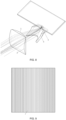
- the optical lens according to the basic embodiment of the present application includes a light incident portion and a light emergent portion, wherein the light incident portion is provided with a first single-directional alignment surface 1, and the light emergent portion is provided with a second single-directional alignment surface 2, the alignment direction of the first single-directional alignment surface 1 and the alignment direction of the second single-directional alignment surface 2 are perpendicular to each other, and the first single-directional alignment surface 1 and the second single-directional collimating surface 2 jointly form a focal point or a focus area of the optical lens.
- the alignment directions of the first single-directional alignment surface 1 and the second single-directional alignment surface 2 of the optical lens are approximately the same as the vertical and horizontal directions of the vehicle, that is, the alignment direction of the first single-directional alignment surface 1 is limited to the horizontal direction or the vertical direction, and correspondingly, the alignment direction of the second single-directional alignment surface 2 is limited to the vertical direction or the horizontal direction.
- the optical lens of the present application will be described mainly with an example in which the alignment direction of the first single-directional alignment surface 1 is limited to the horizontal direction and the alignment direction of the second single-directional alignment surface 2 is limited to the vertical direction.
- the first single-directional alignment surface 1 has the optical characteristics of single-directional collimation of the light emitted by the light source 3.
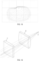
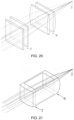
- the "alignment direction" can be understood as follows. In a horizontal section, referring to FIG. 15 , the first single-directional alignment surface 1 produces a converging effect, which can have a certain collimation effect on the light r. Compared with FIG. 16 , in a vertical section, the first single-directional alignment surface 1 has no refraction effect or at most only a very weak refraction effect on the light, (the cutting curve in the vertical direction is almost a straight line), that is, the first single-directional alignment surface 1 has a single-direction collimation effect on the light in the position range of the horizontal section.
- the alignment direction of the first single-directional alignment surface 1 is limited in the horizontal direction.
- the second single-directional alignment surface 2 has the optical characteristics of single-directional collimating the light emitted by the light source 3, which is similar to the first single-directional alignment surface 1, but the difference is: in the horizontal section, the second single-directional alignment surface 2 has no or at best a very weak refraction effect on the light; and in the vertical section, the second single-directional alignment surface 2 produces a converging effect, which can have a certain collimation effect on the light, that is, the second single-directional alignment surface 2 has a single-direction collimation effect on the light in the position range of the vertical section, that is to say, the alignment direction of the second single-directional alignment surface 2 is limited in the vertical direction.
- the alignment direction of the first single-directional alignment surface 1 and the alignment direction of the second single-directional alignment surface 2 are perpendicular to each other.
- the imaging thereof is larger than that in the alignment direction of the second single-directional alignment surface 2, that is, the diffusion degree of the light of the light source 3 in the alignment direction of the first single-directional alignment surface 1 is, after it passes through the optical lens, greater than the diffusion degree of the light thereof in the alignment direction of the second single-directional alignment surface 2.
- the imaging difference is determined by the refractive index of the lens and the lens thickness A between the first single-directional alignment surface 1 and the second single-directional alignment surface 2.
- the light source 3 with a square light-emitting surface is arranged near the focal point or in the focal area of the optical lens, so that the light emitted by the light source 3 pass through the first single-directional alignment surface 1 and the second single-directional alignment surface 2 in sequence to form an asymmetric light shape.
- asymmetric light shape means that the length and width of the light shape are quite different from each other, such as a rectangular light shape.
- the second single-directional alignment surface 2 stretched in the horizontal direction is combined with the first direction alignment surface 1 stretched in the vertical direction, so that the diffusion degree of the light in the horizontal direction is greater than that in the vertical direction, a light shape that is wider in the horizontal direction and relatively narrow in the vertical direction can be obtained.
- FIG. 3 is a screen illuminance diagram of a light shape when a conventional lens images a square light-emitting surface. Comparing the light shapes in FIG. 2 and FIG. 3 , it is obvious that the light shapes obtained by the optical lens of the present invention have obvious asymmetry.
- the first single-directional alignment surface 1 can be regarded as a curved surface which is formed by stretching the collimating curve in the horizontal section along the normal direction of the plane where the collimating curve is located, that is, the curved surface formed by stretching in the vertical direction.
- the second single-directional alignment surface 2 can be regarded as a curved surface which is formed by stretching the alignment curve in the vertical section along the normal direction of the plane where the alignment curve is located, that is, the curved surface formed by stretching in the horizontal direction.
- the curved surface formed by the first single-directional alignment surface 1 and the curved surface formed by the second single-directional alignment surface 2 can be cylindrical surfaces.
- the cylindrical surface can be understood as such an optical curved surface that, taking the first single-directional alignment surface 1 as an example, it produces a converging effect in the horizontal section and can have a certain collimation effect on the light; and it produces, in the vertical section, no refraction or at most only a very weak refraction effect on the light (the cutting curve in the vertical direction is almost a straight line). Wherein, the cutting curve in the horizontal direction does not have to be arc-shaped.
- the curved surface formed by the first single-directional alignment surface 1 and the curved surface formed by the second single-directional alignment surface 2 may be cylindrical-like surfaces.
- the cylindrical-like surface refers to a curved surface that is close to a cylindrical surface in shape, and also has a technical effect similar to the above-mentioned cylindrical surface.
- the cutting curve of the cylindrical surface formed by the first single-directional alignment surface 1 in the horizontal direction can be arc-shaped, and similarly, it is also applies to the cylindrical surface structure formed by the second single-directional alignment surface 2.
- the asymmetry of the asymmetric light shape formed by the above technical solution is caused by the difference in focal lengths on both sides of the optical lens.
- it is related to the ratio of: the magnification of the first single-directional alignment surface 1 to the light shape to the magnification of the second single-directional alignment surface 2 to the light shape, while the ratio of the magnification is determined by the spacing between the first single-directional alignment surface 1 and the second single-directional alignment surface 2. The larger the spacing is, the greater the ratio is, and the more obvious the asymmetry is.
- the thickness of the optical lens can be reduced if the ratio is small.
- the first single-directional alignment surface 1 and the second single-directional alignment surface 2 may also be stepped Fresnel cylindrical surfaces.
- stepped Fresnel cylindrical surface refers to that it is obtained by means of stretching the Fresnel curve and has a single-directional collimation effect on the light.
- Fresnel curve refers to a curve shape in which the plane passing through the optical axis of the Fresnel lens has the same or similar shape as the intersection line of the surface of the Fresnel lens having a plurality of concentric circles.
- the stepped Fresnel cylindrical surface is formed by a series of cylindrical surface structures being arranged horizontally or vertically.
- the stepped Fresnel cylindrical surface structure and the above cylindrical structure can both collimate the light.
- the stepped Fresnel cylindrical surface formed by the first single-directional alignment surface 1 and the stepped Fresnel cylindrical surface formed by the second single-directional alignment surface 2 are arranged as perpendicular to each other, and can also form asymmetric light shapes.
- the first single-directional alignment surface 1 and the second single-directional alignment surface 2 adopt a cylindrical surface or a stepped Fresnel cylindrical surface are descripted respectively.
- the first single-directional alignment surface 1 and the second single-directional alignment surface 2 can be performed a simple deformation, such as, the first single-directional alignment surface 1 is a cylindrical surface and the second single-directional alignment surface 2 is a stepped Fresnel cylindrical surface, or the first single-directional alignment surface 1 is a stepped Fresnel cylindrical surface and the second single-directional alignment surface 2 is a cylindrical surface, as long as the alignment directions of the two are perpendicular to each other.
- the optical lens of the present application is described above, with the example in which the alignment direction of the first single-directional alignment surface 1 is in the horizontal direction and the alignment direction of the second single-directional alignment surface 2 is in the vertical direction.
- the above embodiments are also applicable to the case where the alignment direction of the first single-directional alignment surface 1 is in the vertical direction and the alignment direction of the second single-directional alignment surface 2 is in the horizontal direction.
- the alignment direction of the cylindrical surface on the first single-directional alignment surface 1 is in the vertical direction
- the alignment direction of the cylindrical on the second single-directional alignment surface 2 is in the horizontal direction.
- the embodiment of FIG. 1 from the perspective of the arrangement orientation of the optical lens in FIG. 1 , the alignment direction of the cylindrical surface on the first single-directional alignment surface 1 is in the vertical direction, and the alignment direction of the cylindrical on the second single-directional alignment surface 2 is in the horizontal direction.
- the stepped Fresnel cylindrical surface on the first single-directional alignment surface 1 extends in the horizontal direction, and the alignment direction thereof is in the vertical direction
- the stepped Fresnel cylindrical surface on the second single-direction alignment surface 2 extends in the vertical direction, and the alignment direction is in the horizontal direction.
- the structure of the optical lens is designed above.
- the asymmetric light shape is formed by providing in the light incident portion and the light emergent portion of the optical lens the first single-directional alignment surface 1 and the second single-directional alignment surface 2 with the alignment directions perpendicular to each other.
- the optical lens of the present application can also be designed in the form of the structure of an optical lens group. Further, as shown in FIGS.
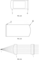
- the first single-directional collimating lens group 6 and the second single-directional collimating lens group 7 are composed of the first single-directional collimating lens group 6 and the second single-directional collimating lens group 7, wherein the first single-directional collimating lens group 6 and the second single-directional collimating lens group 7 jointly form the focus point or the focus area of the optical lens group of the present application, and the alignment direction of the first single-directional collimating lens group 6 and the alignment direction of the second single-directional collimating lens group 7 are perpendicular to each other.
- the optical lens of the present application it can be seen from the optical paths shown in FIGS.
- the first single-directional collimating lens group 6 and the second single-directional collimating lens group 7 respectively have the optical characteristics of one-directional collimation on the light emitted by the light source 3, that is, the collimation direction of the first single-directional collimating lens group 6 is the horizontal direction, and the collimation direction of the second single-directional collimating lens group 7 is the vertical direction.
- the first single-directional collimating lens group 6 and the second single-directional collimating lens group 7 are both composed of at least one single-directional collimating lens.
- FIG. 19 shows an example in which the first single-directional collimating lens group 6 and the second single-directional collimating lens group 7 are both composed of one single-directional collimating lens.
- first single-directional collimating lens group 6 and the second single-directional collimating lens group 7 are both composed of two single-directional collimating lenses.
- first single-directional collimating lens group 6 and the second single-directional collimating lens group 7 both can be composed of multiple single-directional collimating lenses, as long as the first single-directional collimating lens group 6 and the second single-directional collimating lens group 7 have the optical characteristics of single-directional collimation; that is, the collimating directions of the multiple single-directional collimating lenses in the first single-directional collimating lens group 6 are the same, and the collimating directions of the multiple single-directional collimating lenses in the second single-directional collimating lens group 7 are the same.
- the incident surface or the emergent surface of the single-directional collimating lenses is a single-directional collimating curved surface; or, it is also possible that, as shown in FIG. 19 , each of the incident surface and the emergent surface of the single-directional collimating lens is a single-directional collimating curved surface.
- the "single-directional collimating curved surface” refers to a curved surface having the same functions as the first single-directional alignment surface 1 or the second single-directional alignment surface 2 of the optical lens of the present application, and can specifically be a cylindrical surface, a cylinder-like surface or a stepped Fresnel cylindrical surface, etc.
- the two ends of the first single-directional collimating lens group 6 and the two ends of the second single-directional collimating lens group 7 are correspondingly respectively connected through the side walls, and the two are connected into one piece, which effectively ensures the stability of the optical system.
- the light source 3 is arranged near the focal point or in the focal area of the optical lens; or, as shown in FIG. 8 and FIG. 13 , the optical lens of the present application can also be used as a secondary optical element.
- the primary optical element 4 converges the light emitted from the light source 3 to the focal point or focus area of the optical lens, and then the light is injected into the optical lens.
- the primary optical element 4 is provided with a cut-off structure for forming cut-off lines of light and dark, with reference to FIG. 13 , a light shape with cut-off lines of light and dark as shown in FIG. 14 can be obtained.
- the primary optical element 4 can be an optical element such as a mirror, a condenser or a spotlight cup.
- the optical lens group of the present application can also be adapted to the general vehicle lamp system to obtain the same functions.
- FIG. 17 shows an embodiment of a lighting module in prior art.
- a hyperboloid collimating lens 5 is used as a secondary optical element.
- a primary optical element 4 converges the light emitted from the light source 3 and then emits it to the hyperboloid collimating lens 5.
- a cut-off structure provided on the primary optical element 4
- a light shape with cut-off lines of bright and dark as shown in FIG. 18 can be obtained. Comparing the light shapes shown in FIG. 14 and FIG. 18 , it can be clearly seen that the dimensions of the light shape in a horizontal direction and a vertical direction shown in FIG. 18 are relatively close to each other, approximately are square. However, the dimensions of the light shape in the horizontal direction and the vertical direction shown in FIG.
- the light emitted from the light source 3 has diffusion degree in the horizontal direction more than that in the vertical direction, and the light shape is approximately rectangular. It can be seen from the above comparison that the optical lens of the present application can make the light shape have relatively obvious asymmetry. Compared with the prior art, there is no need to add additional optical elements to make the dimensions of the light shapes in the horizontal direction and the vertical direction have a certain difference, which simplifies the structure of the vehicle lamp to a certain extent.
- the optical lens of the present application can form a rectangular light shape, when arranging a vehicle lamp system in a vehicle lamp, taking two vehicle lamp systems as an example, one vehicle lamp system is arranged in a conventional manner, that is, forming a rectangular light shape along the horizontal direction; and the other vehicle lamp system is arranged obliquely, so that the light shape formed by the emitting by the corresponding optical lens is a rectangular light shape with a certain inclination.
- the two parts of the rectangular light shape are overlapped to form a light shape with cut-off lines of light and dark that meets the requirements.
- the optical lens can also be replaced by the optical lens group of the present invention, and the same function can also be achieved.
- the vehicle lamp can be of a flat and wide shape, so that the front part of the vehicle can tend to a streamlined design, which is convenient to reduce the noise caused by the oncoming wind; and moreover, it has a better lighting effect.
Landscapes
- Engineering & Computer Science (AREA)
- General Engineering & Computer Science (AREA)
- Non-Portable Lighting Devices Or Systems Thereof (AREA)
- Lenses (AREA)
Applications Claiming Priority (3)
| Application Number | Priority Date | Filing Date | Title |
|---|---|---|---|
| CN202010367179 | 2020-04-30 | ||
| CN202010628888.9A CN113587041A (zh) | 2020-04-30 | 2020-07-01 | 光学透镜、光学透镜组、车灯系统及车辆 |
| PCT/CN2021/074835 WO2021218265A1 (zh) | 2020-04-30 | 2021-02-02 | 光学透镜、光学透镜组、车灯系统及车辆 |
Publications (2)
| Publication Number | Publication Date |
|---|---|
| EP4130557A1 true EP4130557A1 (de) | 2023-02-08 |
| EP4130557A4 EP4130557A4 (de) | 2023-08-30 |
Family
ID=74757079
Family Applications (1)
| Application Number | Title | Priority Date | Filing Date |
|---|---|---|---|
| EP21796757.9A Pending EP4130557A4 (de) | 2020-04-30 | 2021-02-02 | Optische linse, optische linsengruppe, fahrzeuglampensystem und fahrzeug |
Country Status (6)
| Country | Link |
|---|---|
| US (1) | US12474027B2 (de) |
| EP (1) | EP4130557A4 (de) |
| JP (1) | JP7490810B2 (de) |
| CN (2) | CN113587041A (de) |
| DE (1) | DE112021002606T5 (de) |
| WO (1) | WO2021218265A1 (de) |
Families Citing this family (8)
| Publication number | Priority date | Publication date | Assignee | Title |
|---|---|---|---|---|
| CN113587041A (zh) * | 2020-04-30 | 2021-11-02 | 华域视觉科技(上海)有限公司 | 光学透镜、光学透镜组、车灯系统及车辆 |
| CN113091014B (zh) * | 2021-04-06 | 2022-02-22 | 华域视觉科技(上海)有限公司 | 车灯光学元件、车灯模组和车辆 |
| CN117730230A (zh) | 2021-09-18 | 2024-03-19 | 华域视觉科技(上海)有限公司 | 用于车灯照明装置的光学反射系统和车灯照明装置 |
| WO2023039903A1 (zh) * | 2021-09-18 | 2023-03-23 | 华域视觉科技(上海)有限公司 | 车灯照明装置的光学透反系统和车灯照明装置 |
| CN115968071B (zh) * | 2022-01-30 | 2023-08-25 | 河北省交通规划设计研究院有限公司 | 一种亮度可调的隧道照明系统 |
| CN115507338B (zh) * | 2022-09-30 | 2025-09-30 | 广州维思车用部件有限公司 | 透镜、光学模组及车灯 |
| CN120604076A (zh) * | 2023-04-26 | 2025-09-05 | 华域视觉科技(上海)有限公司 | 一种光学模组及车灯 |
| CN116221647B (zh) * | 2023-05-08 | 2023-07-28 | 常州星宇车灯股份有限公司 | 车灯远光照明系统、照明模组及车辆 |
Family Cites Families (25)
| Publication number | Priority date | Publication date | Assignee | Title |
|---|---|---|---|---|
| JPS598202A (ja) * | 1982-07-05 | 1984-01-17 | 株式会社小糸製作所 | 車輌用灯具 |
| JPH04106802A (ja) | 1990-08-28 | 1992-04-08 | Matsushita Electric Works Ltd | ライトアップ照明装置 |
| JPH04106802U (ja) * | 1991-02-27 | 1992-09-16 | スタンレー電気株式会社 | 車両用照明装置 |
| JP2003100112A (ja) * | 2001-09-26 | 2003-04-04 | Ichikoh Ind Ltd | 車両用ハイマウントストップランプ |
| CN100588989C (zh) * | 2006-06-07 | 2010-02-10 | 本田技研工业株式会社 | 光学装置及移动装置 |
| CN202083837U (zh) * | 2010-11-03 | 2011-12-21 | 中航华东光电有限公司 | 激光投影显示系统 |
| CN102879908B (zh) * | 2012-10-24 | 2015-01-21 | 北京凯普林光电科技有限公司 | 补偿光源系统及列车运行故障动态图像检测设备 |
| CN202886733U (zh) * | 2012-10-24 | 2013-04-17 | 北京凯普林光电科技有限公司 | 补偿光源系统及列车运行故障动态图像检测设备 |
| DE102013102553B4 (de) * | 2013-03-13 | 2020-12-03 | LIMO GmbH | Vorrichtung zur Homogenisierung von Laserstrahlung |
| JP5683648B2 (ja) * | 2013-03-27 | 2015-03-11 | オムロンオートモーティブエレクトロニクス株式会社 | レーザレーダ装置 |
| CN203519855U (zh) * | 2013-11-06 | 2014-04-02 | 福州巴斯光电技术有限公司 | 一种用于车辆雷达传感器的柱面镜组件 |
| CN103728809B (zh) * | 2013-12-30 | 2016-05-11 | 深圳市墨克瑞光电子研究院 | 液晶透镜成像装置和液晶透镜成像方法 |
| AT517887B1 (de) | 2015-10-23 | 2018-06-15 | Zkw Group Gmbh | Mikroprojektions-Lichtmodul für Fahrzeugscheinwerfer |
| JP6690960B2 (ja) * | 2016-02-18 | 2020-04-28 | 株式会社小糸製作所 | 車両用灯具 |
| CN107091443B (zh) * | 2016-02-18 | 2019-10-18 | 株式会社小糸制作所 | 车辆用灯具 |
| JP6791644B2 (ja) * | 2016-03-24 | 2020-11-25 | 株式会社小糸製作所 | 車両用前照灯 |
| JP2018041664A (ja) * | 2016-09-08 | 2018-03-15 | スタンレー電気株式会社 | 車両用灯具 |
| CN206330082U (zh) * | 2016-09-28 | 2017-07-14 | 法雷奥照明湖北技术中心有限公司 | 光图案化装置与车灯 |
| CN108302470B (zh) * | 2016-09-28 | 2025-05-30 | 法雷奥照明湖北技术中心有限公司 | 光图案化装置与车灯 |
| DE102016125887A1 (de) * | 2016-12-29 | 2018-07-05 | Automotive Lighting Reutlingen Gmbh | Lichtmodul für Kraftfahrzeugscheinwerfer |
| DE102017117376A1 (de) * | 2017-08-01 | 2019-02-07 | HELLA GmbH & Co. KGaA | Scheinwerfer, insbesondere Scheinwerfer eines Kraftfahrzeugs |
| KR102036749B1 (ko) * | 2017-12-14 | 2019-10-28 | 에스엘 주식회사 | 차량용 램프 |
| US10642053B2 (en) * | 2018-03-26 | 2020-05-05 | Simmonds Precision Products, Inc. | Scanned linear illumination of distant objects |
| CN108549085B (zh) * | 2018-04-12 | 2024-03-19 | 北醒(北京)光子科技有限公司 | 一种发射镜头、面阵激光雷达及移动平台 |
| CN113587041A (zh) * | 2020-04-30 | 2021-11-02 | 华域视觉科技(上海)有限公司 | 光学透镜、光学透镜组、车灯系统及车辆 |
-
2020
- 2020-07-01 CN CN202010628888.9A patent/CN113587041A/zh active Pending
- 2020-07-01 CN CN202021274171.0U patent/CN212618084U/zh active Active
-
2021
- 2021-02-02 EP EP21796757.9A patent/EP4130557A4/de active Pending
- 2021-02-02 DE DE112021002606.2T patent/DE112021002606T5/de active Pending
- 2021-02-02 WO PCT/CN2021/074835 patent/WO2021218265A1/zh not_active Ceased
- 2021-02-02 JP JP2022561683A patent/JP7490810B2/ja active Active
- 2021-02-02 US US17/922,142 patent/US12474027B2/en active Active
Also Published As
| Publication number | Publication date |
|---|---|
| CN113587041A (zh) | 2021-11-02 |
| US20230213162A1 (en) | 2023-07-06 |
| EP4130557A4 (de) | 2023-08-30 |
| WO2021218265A1 (zh) | 2021-11-04 |
| DE112021002606T5 (de) | 2023-03-16 |
| CN212618084U (zh) | 2021-02-26 |
| JP7490810B2 (ja) | 2024-05-27 |
| JP2023521397A (ja) | 2023-05-24 |
| US12474027B2 (en) | 2025-11-18 |
Similar Documents
| Publication | Publication Date | Title |
|---|---|---|
| US12474027B2 (en) | Optical lens, optical lens group, vehicle lamp system, and vehicle | |
| US11333313B2 (en) | Vehicle lamp module and vehicle using same | |
| JP6948818B2 (ja) | 光ビームを放出するための自動車両ヘッドライト・モジュール | |
| US20220316676A1 (en) | Automotive lamp optical element and automotive headlamp | |
| US11731552B2 (en) | Low beam optical module, low beam illumination module, vehicle lamp and vehicle | |
| US11708021B2 (en) | Small-sized vehicle-mounted projector light system | |
| WO2020021825A1 (ja) | ヘッドライト装置 | |
| US12405480B2 (en) | Lens unit, optical lens, illumination module, vehicle light, and vehicle | |
| US11788702B2 (en) | Headlight module and headlight device | |
| CN113958921A (zh) | 照明模组、照明装置及车辆 | |
| CN209782494U (zh) | 棱镜全反射式近光模组以及车灯 | |
| CN216644082U (zh) | 光学系统、车灯模组、车灯和车辆 | |
| US11079084B2 (en) | Direct-type automobile headlamp module and automobile headlamp | |
| CN210219619U (zh) | 一种近光iii区照明模块、遮光板、照明装置及车辆 | |
| US11306892B2 (en) | Vehicle lamp III-zone illumination structure, vehicle lamp condenser, automobile illumination module and automobile | |
| US11454366B2 (en) | Automobile lamp lighting system, automobile lamp assembly and automobile | |
| CN219510649U (zh) | 一种照明装置和车灯 | |
| CN215372307U (zh) | 照明模组、照明装置及车辆 | |
| CN102661537B (zh) | 背光模组及液晶显示器 | |
| CN220958053U (zh) | 反射式造型的展宽光学系统、照明装置、车灯及车辆 | |
| US12510220B2 (en) | Optical element, vehicle light module, vehicle light and vehicle | |
| CN218032953U (zh) | 一种多角度均匀发光厚壁光导结构 | |
| CN223826104U (zh) | 一种提升点亮均匀性的光学系统 | |
| CN222597457U (zh) | 用于汽车前大灯的光学系统 | |
| JP7495702B2 (ja) | 照明装置 |
Legal Events
| Date | Code | Title | Description |
|---|---|---|---|
| STAA | Information on the status of an ep patent application or granted ep patent |
Free format text: STATUS: THE INTERNATIONAL PUBLICATION HAS BEEN MADE |
|
| PUAI | Public reference made under article 153(3) epc to a published international application that has entered the european phase |
Free format text: ORIGINAL CODE: 0009012 |
|
| STAA | Information on the status of an ep patent application or granted ep patent |
Free format text: STATUS: REQUEST FOR EXAMINATION WAS MADE |
|
| 17P | Request for examination filed |
Effective date: 20221027 |
|
| AK | Designated contracting states |
Kind code of ref document: A1 Designated state(s): AL AT BE BG CH CY CZ DE DK EE ES FI FR GB GR HR HU IE IS IT LI LT LU LV MC MK MT NL NO PL PT RO RS SE SI SK SM TR |
|
| DAV | Request for validation of the european patent (deleted) | ||
| DAX | Request for extension of the european patent (deleted) | ||
| STAA | Information on the status of an ep patent application or granted ep patent |
Free format text: STATUS: EXAMINATION IS IN PROGRESS |
|
| A4 | Supplementary search report drawn up and despatched |
Effective date: 20230727 |
|
| RIC1 | Information provided on ipc code assigned before grant |
Ipc: F21S 41/25 20180101AFI20230721BHEP |
|
| 17Q | First examination report despatched |
Effective date: 20230810 |
|
| RIC1 | Information provided on ipc code assigned before grant |
Ipc: F21S 41/25 20180101AFI20230810BHEP |