EP4130587A1 - Frischluftmodul und klimaanlage - Google Patents
Frischluftmodul und klimaanlage Download PDFInfo
- Publication number
- EP4130587A1 EP4130587A1 EP20929641.7A EP20929641A EP4130587A1 EP 4130587 A1 EP4130587 A1 EP 4130587A1 EP 20929641 A EP20929641 A EP 20929641A EP 4130587 A1 EP4130587 A1 EP 4130587A1
- Authority
- EP
- European Patent Office
- Prior art keywords
- air
- fresh air
- cavity
- partition plate
- middle partition
- Prior art date
- Legal status (The legal status is an assumption and is not a legal conclusion. Google has not performed a legal analysis and makes no representation as to the accuracy of the status listed.)
- Granted
Links
Images


Classifications
-
- F—MECHANICAL ENGINEERING; LIGHTING; HEATING; WEAPONS; BLASTING
- F24—HEATING; RANGES; VENTILATING
- F24F—AIR-CONDITIONING; AIR-HUMIDIFICATION; VENTILATION; USE OF AIR CURRENTS FOR SCREENING
- F24F13/00—Details common to, or for air-conditioning, air-humidification, ventilation or use of air currents for screening
- F24F13/08—Air-flow control members, e.g. louvres, grilles, flaps or guide plates
- F24F13/10—Air-flow control members, e.g. louvres, grilles, flaps or guide plates movable, e.g. dampers
-
- F—MECHANICAL ENGINEERING; LIGHTING; HEATING; WEAPONS; BLASTING
- F24—HEATING; RANGES; VENTILATING
- F24F—AIR-CONDITIONING; AIR-HUMIDIFICATION; VENTILATION; USE OF AIR CURRENTS FOR SCREENING
- F24F1/00—Room units for air-conditioning, e.g. separate or self-contained units or units receiving primary air from a central station
- F24F1/0007—Indoor units, e.g. fan coil units
- F24F1/0035—Indoor units, e.g. fan coil units characterised by introduction of outside air to the room
-
- F—MECHANICAL ENGINEERING; LIGHTING; HEATING; WEAPONS; BLASTING
- F24—HEATING; RANGES; VENTILATING
- F24F—AIR-CONDITIONING; AIR-HUMIDIFICATION; VENTILATION; USE OF AIR CURRENTS FOR SCREENING
- F24F1/00—Room units for air-conditioning, e.g. separate or self-contained units or units receiving primary air from a central station
- F24F1/0007—Indoor units, e.g. fan coil units
- F24F1/0011—Indoor units, e.g. fan coil units characterised by air outlets
- F24F1/0014—Indoor units, e.g. fan coil units characterised by air outlets having two or more outlet openings
-
- F—MECHANICAL ENGINEERING; LIGHTING; HEATING; WEAPONS; BLASTING
- F24—HEATING; RANGES; VENTILATING
- F24F—AIR-CONDITIONING; AIR-HUMIDIFICATION; VENTILATION; USE OF AIR CURRENTS FOR SCREENING
- F24F1/00—Room units for air-conditioning, e.g. separate or self-contained units or units receiving primary air from a central station
- F24F1/0007—Indoor units, e.g. fan coil units
- F24F1/0018—Indoor units, e.g. fan coil units characterised by fans
- F24F1/0022—Centrifugal or radial fans
-
- F—MECHANICAL ENGINEERING; LIGHTING; HEATING; WEAPONS; BLASTING
- F24—HEATING; RANGES; VENTILATING
- F24F—AIR-CONDITIONING; AIR-HUMIDIFICATION; VENTILATION; USE OF AIR CURRENTS FOR SCREENING
- F24F1/00—Room units for air-conditioning, e.g. separate or self-contained units or units receiving primary air from a central station
- F24F1/0007—Indoor units, e.g. fan coil units
- F24F1/0018—Indoor units, e.g. fan coil units characterised by fans
- F24F1/0033—Indoor units, e.g. fan coil units characterised by fans having two or more fans
-
- F—MECHANICAL ENGINEERING; LIGHTING; HEATING; WEAPONS; BLASTING
- F24—HEATING; RANGES; VENTILATING
- F24F—AIR-CONDITIONING; AIR-HUMIDIFICATION; VENTILATION; USE OF AIR CURRENTS FOR SCREENING
- F24F1/00—Room units for air-conditioning, e.g. separate or self-contained units or units receiving primary air from a central station
- F24F1/0007—Indoor units, e.g. fan coil units
- F24F1/0071—Indoor units, e.g. fan coil units with means for purifying supplied air
- F24F1/0073—Indoor units, e.g. fan coil units with means for purifying supplied air characterised by the mounting or arrangement of filters
-
- F—MECHANICAL ENGINEERING; LIGHTING; HEATING; WEAPONS; BLASTING
- F24—HEATING; RANGES; VENTILATING
- F24F—AIR-CONDITIONING; AIR-HUMIDIFICATION; VENTILATION; USE OF AIR CURRENTS FOR SCREENING
- F24F13/00—Details common to, or for air-conditioning, air-humidification, ventilation or use of air currents for screening
- F24F13/02—Ducting arrangements
-
- F—MECHANICAL ENGINEERING; LIGHTING; HEATING; WEAPONS; BLASTING
- F24—HEATING; RANGES; VENTILATING
- F24F—AIR-CONDITIONING; AIR-HUMIDIFICATION; VENTILATION; USE OF AIR CURRENTS FOR SCREENING
- F24F13/00—Details common to, or for air-conditioning, air-humidification, ventilation or use of air currents for screening
- F24F13/20—Casings or covers
-
- F—MECHANICAL ENGINEERING; LIGHTING; HEATING; WEAPONS; BLASTING
- F24—HEATING; RANGES; VENTILATING
- F24F—AIR-CONDITIONING; AIR-HUMIDIFICATION; VENTILATION; USE OF AIR CURRENTS FOR SCREENING
- F24F13/00—Details common to, or for air-conditioning, air-humidification, ventilation or use of air currents for screening
- F24F13/20—Casings or covers
- F24F2013/205—Mounting a ventilator fan therein
Definitions
- This application relates to the field of air conditioners, and in particular to a fresh air module and an air conditioner.
- air conditioners on the market are usually equipped with fresh air modules, which may be used to introduce fresh air from outdoor environment into indoor environment to replenish the fresh air of indoor environment and improve the air quality of indoor environment.
- the conventional fresh air module is usually configured with a fresh air duct in its interior for installing a fan assembly.
- the fresh air duct of this conventional fresh air module is usually an integral and large air cavity, and the wind pressure generated by the fan assembly installed in the fresh air duct is small, resulting in a small fresh air volume output from the fresh air module.
- the main object of this application is to propose a fresh air module, which aims to optimize the fresh air duct of the fresh air module and increase fresh air volume output from the fresh air module.
- this application provides a fresh air module, including:
- the housing includes a bottom case and a cover that fits and covers the bottom case, and wherein the bottom case is configured with a first cavity, and the middle partition plate is installed at an opening of the first cavity to cooperate with the first cavity to form the air outlet cavity.
- the bottom case is further provided with a second cavity located at a side of the first cavity, and the air inlet cavity is formed between the first cavity and the cover, and wherein the fresh air duct further includes an air passage cavity between the middle partition plate and the cover, and the ventilation hole of the middle partition plate is communicated with the air inlet cavity via the air passage cavity.
- the fan assembly is installed in the first cavity and includes a centrifugal wind wheel and a first motor, and wherein an end of the centrifugal wind wheel is connected with the first motor, and an other end of the centrifugal wind wheel forms an air inlet end and corresponds to the ventilation hole of the middle partition plate.
- the middle partition plate is provided with an air guide ring at a periphery of the ventilation hole, and the air guide ring is extended from the periphery of the ventilation hole toward the air inlet end of the centrifugal wind wheel in a tapered way.
- the air inlet end of the centrifugal wind wheel is configured with an air induction ring, a constricted end of the air guide ring is extended into the air induction ring, and a clearance gap is formed between an outer peripheral wall of the air guide ring and an inner peripheral wall of the air induction ring for the centrifugal wind wheel to rotate.
- a bottom portion of the bottom case has a motor installation cavity in a direction away from the middle partition plate, and the motor installation cavity is opened toward the first cavity for the first motor to be installed.
- the middle partition plate forms the ventilation hole in a central area of the middle partition plate, so as to correspond to the air inlet end of the centrifugal wind wheel, and wherein a ratio of a ventilation face area of the ventilation hole of the middle partition plate to a side face area of the middle partition plate is not less than 1/4 and not more than 3/4.
- a side wall of the bottom case corresponding to the first cavity is provided with a fresh air outlet, and the fresh air outlet outputs air forward
- a side wall of the bottom case corresponding to the second cavity is provided with a fresh air inlet, and the fresh air inlet intakes air from rear.
- the fresh air module further includes a temperature sensor, wherein a windward surface of the middle partition plate is configured with a sensor fixing member located at a position of the middle partition plate close to a front air inlet cavity and fixes the temperature sensor.
- the fresh air module further includes a purification assembly, wherein the purification assembly is installed on the middle partition plate in a drawable manner along an inner-outer direction of the housing and is located at an air inlet side of the ventilation hole of the middle partition plate.
- the fresh air module further includes a valve assembly, wherein the valve assembly includes a fresh air door rotatably installed at the fresh air inlet, and a second motor connected with the fresh air door, and wherein the second motor drives the fresh air door to turn over to open or close the fresh air inlet.
- the fresh air module includes a housing, a middle partition plate and a fan assembly.
- the housing is configured with a fresh air duct, and the fresh air duct includes an air inlet cavity and an air outlet cavity.
- the middle partition plate is arranged in the fresh air duct, is located between the air inlet cavity and the air outlet cavity, and is provided with a ventilation hole which communicates the air inlet cavity and the air outlet cavity.
- the fan assembly is installed in the air outlet cavity.
- the air inlet cavity of the fresh air module communicates with outdoor environment through a fresh air pipe, and the air outlet cavity of the fresh air module communicates with the second air outlet.
- the air conditioner is any one of a wall-mounted air conditioner indoor unit, a cabinet air conditioner indoor unit, an air machine, a ceiling-embedded air conditioner indoor unit, or a mobile air conditioner.
- the casing of the wall-mounted air conditioner indoor unit includes a chassis, a face frame and a panel; the fresh air module is installed at an end of the chassis, and an end of the panel is provided with the second air outlet.
- the middle partition plate is arranged in the fresh air duct of the fresh air module, so that the fresh air duct is divided into an air inlet cavity and an air outlet cavity, and the air inlet cavity and the air outlet cavity are communicated through the ventilation hole on the middle partition plate, so that for the entire fresh air duct, the volume of the air outlet cavity is smaller than that of the entire fresh air duct. Therefore, when the fan assembly rotates in the air outlet cavity, the fan assembly quickly sucks air from the ventilation hole of the middle partition plate and squeezes it into the air outlet cavity, thus making the air pressure in the air outlet cavity higher, and in turn increasing the rate at which the fan assembly outputs fresh air volume from the fresh air outlet and greatly increasing fresh air volume output from the fresh air module.
- reference sign name reference sign name 100 air conditioner 333 air passage cavity 110 casing 301 fresh air inlet 111 chassis 302 fresh air outlet 112 frame 400 fan assembly 113 panel 410 centrifugal wind wheel 101 air inlet 411 air induction ring 102 first air outlet 420 first motor 103 second air outlet 500 purification assembly 200 fresh air module 510 mounting frame 300 housing 520 purification member 310 bottom case 600 middle partition plate 311 first cavity 610 ventilation hole 312 second cavity 611 air guide ring 313 motor installation cavity 620 sensor fixing member 320 cover 700 valve assembly 330 fresh air duct 710 fresh air door 331 air inlet cavity 720 second motor 332 air outlet cavity 800 fresh air pipe
- a fresh air module 200 and an air conditioner including the fresh air module 200 are provided according to certain embodiments of the disclosure.
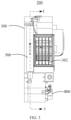
- the dotted arrow in FIG. 5 indicates the flow direction of airflow.
- the fresh air module 200 may improve and optimize the fresh air duct of the fresh air module 200 to increase the fresh air volume output from the fresh air module 200.
- the air conditioner may be any one of an indoor unit of a wall-mounted air conditioner, an indoor unit of a cabinet air conditioner, an air machine, an indoor unit of a ceiling-type air conditioner, or a mobile air conditioner.
- the introduction is mainly based on the case where the air conditioner is the indoor unit of the wall-mounted air conditioner indoor unit, which can provide reference for other types of air conditioners.
- the fresh air module 200 includes a housing 300, a middle partition plate 600 and a fan assembly 400.
- the housing 300 defines a fresh air duct 330, which includes an air inlet cavity 331 and an air outlet cavity 332.
- the middle partition plate 600 is also provided with a ventilation hole 610 which communicates the air inlet cavity 331 and the air outlet cavity 332.
- the fan assembly 400 is installed in the air outlet cavity 332.
- the housing 300 of the fresh air module 200 may have a fresh air inlet 301 at its bottom, and the fresh air inlet 301 communicates with the air inlet cavity 331.
- the housing 300 may be provided with a fresh air outlet 302 at its top or front side or left or right side, and the fresh air outlet 302 communicates with the air outlet cavity 332.
- the housing 300 may be provided with a fresh air inlet 301 at its bottom, which is open to the rear side of the fresh air module 200.
- the fresh air inlet 301 is communicated with the outdoor environment through a fresh air pipe 800, so that the air enters from the rear.
- the housing 300 may be provided with a fresh air outlet 302 at the front side thereof, so as to output air at the front side of the fresh air module 200.
- the fan assembly 400 when the fresh air module 200 is in operation, the fan assembly 400 is turned on, and the fresh air is driven to enter the air inlet cavity 331 of the fresh air duct 330 from the fresh air inlet 301 by the fan assembly 400, and then enters the air outlet cavity 332 through the ventilation hole 610 of the middle partition plate 600, and is moved to the fresh air outlet 302 by the fan assembly 400 in the air outlet cavity 332 along a radial direction of the fan assembly 400, and finally blows out from the fresh air outlet 302.
- the middle partition plate 600 divides the fresh air duct 330 into an air inlet cavity 331 and an air outlet cavity 332, the air outlet cavity 332 is communicated through the ventilation hole 610 on the middle partition plate 600, which is equivalent to dividing the fresh air duct 330 into segments. Therefore, for the entire fresh air duct 330, the volume of the air outlet cavity 332 is smaller than that of the entire fresh air duct 330.
- the fan assembly 400 when the fan assembly 400 rotates in the air outlet cavity 332, the fan assembly 400 quickly sucks air from the ventilation hole 610 of the middle partition plate 600 and pushes it to the air outlet cavity 332, thus making the air pressure in the air outlet cavity 332 higher, and in turn increasing the rate at which the fan assembly 400 outputs the fresh air from the fresh air outlet 302 and greatly increasing the fresh air volume output from the fresh air module 200.
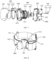
- the purification assembly 500 includes a mounting frame 510 and a purification member 520 mounted on the mounting frame 510 (as shown in FIG. 7 ).
- the purification member 520 may be used to remove any one or more of air pollutants such as dust, fine particles, microorganisms, and organic volatile gases (e.g., formaldehyde) in the air.
- the type of the purification member 520 may be selected according to its function.
- the purification member 520 may be any one or two of an ordinary filter screen, a HEPA screen, a formaldehyde remover or an IFD filter.
- the purification member 520 may be any one or more of a primary-efficiency filter, a mediumefficiency filter and a high-efficiency filter.
- the middle partition plate 600 is arranged in the fresh air duct 330 of the fresh air module 200, so that the fresh air duct 330 is divided into the air inlet cavity 331 and the air outlet cavity 332, and the air inlet cavity 331 and the air outlet cavity 332 are communicated through the ventilation hole 610 on the middle partition plate 600, so that for the entire fresh air duct 330, the volume of the air outlet cavity 332 is smaller than that of the entire fresh air duct 330.
- the fan assembly 400 when the fan assembly 400 rotates in the air outlet cavity 332, the fan assembly 400 quickly sucks air from the ventilation hole 610 of the middle partition plate 600 and pushes it into the air outlet cavity 332, thus making the air pressure in the air outlet cavity 332 higher, and in turn increasing the rate at which the fan assembly 400 outputs the fresh air from the fresh air outlet 302 and greatly increasing the fresh air volume output from the fresh air module 200.
- the housing 300 includes a bottom case 310 and a cover that fits and covers the bottom case 310.
- the bottom case 310 is provided with a first cavity 311
- the middle partition plate 600 is installed at an opening of the first cavity 311 to cooperate with the first cavity 311 to form the air outlet cavity 332.
- the middle partition plate 600 is substantially matched with a shape of the opening of the first cavity 311. During assembling, the middle partition plate 600 is assembled at the opening of the first cavity 311, and then the cover 320 is covered on the bottom case 310 to surround the middle partition plate 600 between the bottom case 310 and the cover 320.
- the bottom case 310 is further provided with a second cavity 312 located at one side of the first cavity 311, and the air inlet cavity 331 is formed between the first cavity 311 and the cover 320.
- An air passage cavity 333 is formed between the middle partition plate 600 and the cover 320, and the air passage cavity 333 communicates the ventilation hole 610 of the middle partition plate 600 with the air inlet cavity 331.
- the cover 320 is covered on the bottom case 310, and in particular, a part of the cover 320 covers above the second cavity 312 of the bottom case 310, and cooperates with the second cavity 312 to form the air inlet cavity 331.
- the airflow enters through the fresh air inlet, then enters the air outlet cavity 332 through the air inlet cavity 331, the air passage cavity 333 and the ventilation hole 610 of the middle partition plate 600, and finally blows out from the fresh air outlet 302.
- the middle partition plate 600 may be installed at the opening of the first cavity 311 of the bottom case 310, and then the middle partition plate 600 and the bottom case 310 may be snapconnected by a snap structure and/or connected into an integral piece by a screw structure. Then, the cover 320 is covered on the integral piece formed by connecting the bottom case 310 with the middle partition plate 600, and the cover 320 may be connected and fixed with the bottom case 310 and/or the middle partition plate 600 by any one or both of the snap structure and the screw structure.
- the fan assembly 400 is installed in the first cavity 311.
- the fan assembly 400 includes a centrifugal wind wheel 410 and a first motor 420.
- An end of the centrifugal wind wheel 410 is connected to the first motor 420, and the other end of the centrifugal wind wheel 410 forms an air inlet end and corresponds to the ventilation hole 610 of the middle partition plate 600.
- the airflow in the air inlet cavity 331 passes through the ventilation hole 610 of the middle partition plate 600, then directly enters the centrifugal wind wheel 410 from the air inlet end of the centrifugal wind wheel 410, and then is propelled by the centrifugal wind wheel 410 at a high speed, thus enhancing the air supply efficiency of the centrifugal wind wheel 410.
- the first motor 420 of the fan assembly 400 is usually installed on the bottom case 310 from the bottom surface of the bottom case 310 through a separately disposed motor cover. Therefore, the installation direction to install the first motor 420 is opposite to the assembling direction to assemble the centrifugal wind wheel 410, the middle partition plate 600 or the cover 320, and the assembling direction needs to be repeatedly adjusted during the assembly process, such as adjusting the direction of driving the screws. This assembling method is complicated and the assembling efficiency is low.
- a bottom portion of the bottom case 310 has a motor installation cavity 313 in a direction away from the middle partition plate 600, and the motor installation cavity 313 has an opening facing the first cavity 311 for the first motor 420 to be installed.
- the first motor 420 may be installed into the motor installation cavity 313 of the bottom case 310 from the opening of the bottom case 310, and then the centrifugal wind wheel 410 is installed in the first cavity 311 of the bottom case 310 and connected with the first motor 420.
- the assembling direction of the first motor 420 is the same as those of the centrifugal wind wheel 410, the middle partition plate 600, and the cover 320, and repeated adjustment of the assembling direction is not needed.
- the screws may be driven from the forward direction, which may achieve rapid assembling.
- the middle partition plate 600 is formed with a ventilation hole 610 in its central area to correspond to the air inlet end of the centrifugal wind wheel 410.
- a ventilation area of the ventilation hole 610 is substantially the same as or slightly smaller than an air inlet area of the air inlet end of the centrifugal wind wheel 410, such that most of the airflow passing through the ventilation hole 610 may enter the centrifugal wind wheel 410 to avoid the air volume loss caused by axial diffusion.
- a ratio of the ventilation area of the ventilation hole 610 of the middle partition plate 600 to the side area of the middle partition plate 600 is not less than 1/4 and not more than 3/4, so as to ensure that the size of the ventilation hole 610 is substantially the same as or slightly smaller than the air inlet area of the air inlet end of the centrifugal wind wheel 410.
- the middle partition plate 600 may be provided with an air guide ring 611 at the periphery of the ventilation hole 610, and the air guide ring 611 extends from the periphery of the ventilation hole 610 toward the air inlet end of the centrifugal wind wheel 410 in a tapered shape.
- the air guide ring 611 is protruded from the periphery of the ventilation hole 610 toward the air inlet end of the centrifugal wind wheel 410, and the diameter of the air guide ring 611 is gradually reduced, so that the air guide ring 611 is arranged in a tapered shape.
- a flared end of the air guide ring 611 is correspondingly located at the ventilation hole 610, and the constricted end of the air guide ring 611 faces the air inlet end of the centrifugal wind wheel 410.
- the air guide ring 611 may reduce the resistance of the airflow passing through the ventilation hole 610, which helps to guide the airflow to accurately flow into the air inlet end of the centrifugal wind wheel 410 after passing through the ventilation hole 610, so as to prevent the airflow from diffusing at the air outlet side of the ventilation hole 610 and failing to enter the centrifugal wind wheel 410.
- the air inlet end of the centrifugal wind wheel 410 is provided with an air induction ring 411, the constricted end of the air guide ring 611 extends into the air induction ring 411, and a clearance gap is formed between an outer peripheral wall of the air guide ring 611 and an inner peripheral wall of the air induction ring 411 for the centrifugal wind wheel 410 to rotate.
- the airflow guided by the air guide ring 611 may directly reach the inside of the centrifugal wind wheel 410 after being separated from the air guide ring 611, thus increasing the air intake volume of the centrifugal wind wheel 410, and in turn increasing the air volume and air supply efficiency of the centrifugal wind wheel 410.
- a clearance gap is provided between the outer peripheral wall of the air guide ring 611 and the inner peripheral wall of the air induction ring 411 in order to avoid the interference between the wind guide ring and the air induction ring, which may make the air induction ring 411 of the centrifugal wind wheel 410 rotate around the outer periphery of the air guide ring 611, thus ensuring that the wind guide ring and the air induction ring do not interfere each other during the rotation.
- the fresh air module 200 further includes a temperature sensor, which is suitable for detecting the temperature of fresh air.
- the windward surface of the middle partition plate 600 is provided with a sensor fixing member 620, which is located at a position of the middle partition plate 600 close to the front air inlet cavity 331, and is suitable for fixing the temperature sensor.
- the sensor fixing member 620 is used to fix the temperature sensor, the temperature sensor may be positioned closer to the fresh air inlet 301, which is beneficial to accurately detecting the temperature of fresh air.
- the sensor fixing member 620 may be a wire clamp for clamping and fixing the temperature sensor, a limiting slot for limiting the movement of the temperature sensor, or a fixing sleeve for the temperature sensor to pass through. It may be selected according to the cost and difficulty of design, which is not limited here.
- the fresh air module 200 further includes a purification assembly 500, which is of a pull-push type and installed on the middle partition plate 600 along an inner-outer direction of the housing 300, and is located at the air inlet side of the ventilation hole 610 of the middle partition plate 600.
- a purification assembly 500 which is of a pull-push type and installed on the middle partition plate 600 along an inner-outer direction of the housing 300, and is located at the air inlet side of the ventilation hole 610 of the middle partition plate 600.
- the housing 300 is provided with an installation opening at one side of the fresh air outlet 302, and the installation opening is arranged in a strip shape and extends in the same direction as one side of the fresh air outlet 302.
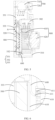
- the purification assembly 500 is installed on the middle partition plate 600 and drawable from the installation opening. The user may draw out the purification assembly 500 from the installation opening (in the direction indicated by "F" in FIG. 4 ) for cleaning or replacement.
- the purification assembly 500 may also be pushed into the air inlet side of the ventilation hole 610 of the middle partition plate 600 from the installation opening, so as to purify the airflow from the air inlet cavity 331 to the air outlet cavity 332 through the ventilation hole 610 and remove the pollutants in the air.
- the air inlet end of the fan assembly 400 corresponds to the ventilation hole 610
- the purification assembly 500 corresponds to the air inlet end of the fan assembly 400.
- the airflow in the air inlet cavity 331 is first purified into clean fresh air by the purification assembly 500, and then the clean fresh air enters the air inlet end of the fan assembly 400 from the ventilation hole 610, and is finally blown out by the fan assembly 400 along the radial direction of the fan assembly 400.
- the air passage cavity 333 between the middle partition plate 600 and the cover 320 have a larger space, so that a purification surface of the purification assembly 500 through which the air passes for purification may be designed to be larger according to the size of the ventilation hole 610, thereby increasing the air purification efficiency of the purification assembly 500. Since the purification assembly 500 is designed to be larger, the air volume that may be purified by the purification assembly 500 is correspondingly increased, thus prolonging the life of the purification assembly 500 and taking a longer period before a new purification assembly 500 is needed.
- the fresh air module 200 further includes a valve assembly 700 installed at the fresh air inlet 301, and the valve assembly 700 includes a fresh air door 710 which is rotatable relative to the fresh air inlet 301, and a second motor 720 connected with the fresh air door 710.
- the second motor 720 drives the fresh air door 710 to turn over, so that the fresh air door 710 opens or closes the fresh air inlet 301.
- the fresh air inlet 301 may be closed by the fresh air door to prevent the outdoor cold air from entering and freezing the fresh air module 200 or entering the indoor environment through the fresh air module 200.
- the present application also provides an air conditioner 100, which includes a casing 110 and a fresh air module 200 installed in the casing 110.
- the detained structure of the fresh air module 200 can be referred to the above embodiments.
- the air conditioner 100 can be any one of an indoor unit of a wall-mounted air conditioner, an indoor unit of a cabinet air conditioner, an air machine, an indoor unit of a ceiling-type air conditioner, or a mobile air conditioner.
- the description will be given by taking the air conditioner 100 as the indoor unit of the wall-mounted air conditioner as an example.
- the casing 110 is provided with an air inlet 101, a first air outlet 102 and a second air outlet 103.
- the air inlet 101 is communicated with the first air outlet 102.
- the fresh air module 200 is installed in the casing 110, the air inlet cavity 331 of the fresh air module 200 is suitable for communicating with the outdoor environment through the fresh air pipe 800, and the air outlet cavity 332 of the fresh air module 200 is suitable for communicating with the second air outlet 103.
- the air conditioner 100 has an indoor air circulation mode and a fresh air mode.
- the air from indoor environment enters the casing 110 through the air inlet 101, cold air or hot air is generated after the heat exchange by the heat exchange assembly inside the casing 110, and then the cold air or hot air is blown back to the indoor environment through the first air outlet 102 to achieve the indoor air circulation; and in the fresh air mode, the air from outdoor environment enters the fresh air module 200 through the fresh air pipe 800, and clean fresh air is generated after purification by the purification assembly of the fresh air module.
- the fresh air is blown from the fresh air outlet 302 of the fresh air module 200 to the second air outlet 103 of the casing 110, and finally blown from the second air outlet 103 to the indoor environment, so as to supplement fresh air for the indoor environment.
- the casing 110 includes a chassis 111, a frame 112 and a panel 113.
- the fresh air module 200 is installed at an end of the chassis 111, and the fresh air outlet 302 of the fresh air module 200 faces toward the panel 113.
- An end of the panel 113 is provided with a second air outlet 103, so that the air conditioner 100 may send fresh air forward, and so that the fresh air may accurately reach the position where the user is located.
- the second air outlet 103 may be composed of a plurality of micro-pores penetrating through the panel 113, so that the airflow is broken into strands of smaller filament airflow after the fresh air is blown out from the plurality of micro-pores, the wind speed is reduced, the airflow becomes soft and will not be blown directly to the user, thus avoiding causing discomfort to the user.
- an insertion part 340 is formed at the bottom and/or back of the housing 300 of the fresh air module 200 (the insertion part 340 may be seen in FIG. 4 ), and a fixing part 350 is formed at the front and/or top of the housing 300 (the fixing part 350 may be seen in FIG. 2 ).
- the chassis of the air conditioner is provided with a insertion slot for the insertion part 340 to be inserted correspondingly, and a connecting part for the fixing part 350 to be connected and fixed.
- the fresh air module 200 is placed in the chassis, and then the insertion part 340 of the fresh air module 200 is inserted and connected with the insertion slot of the chassis to position the fresh air module 200 on the chassis.
- the fixing part 350 of the fresh air module 200 and the connecting part of the chassis are connected through connectors (such as screws), so that the fresh air module 200 is fixed on the chassis, and the installation of the fresh air module 200 is completed.
Landscapes
- Engineering & Computer Science (AREA)
- Chemical & Material Sciences (AREA)
- Combustion & Propulsion (AREA)
- Mechanical Engineering (AREA)
- General Engineering & Computer Science (AREA)
- Air-Conditioning Room Units, And Self-Contained Units In General (AREA)
- Air-Flow Control Members (AREA)
- Structures Of Non-Positive Displacement Pumps (AREA)
Applications Claiming Priority (2)
| Application Number | Priority Date | Filing Date | Title |
|---|---|---|---|
| CN202010240347.9A CN111561744A (zh) | 2020-03-30 | 2020-03-30 | 新风模块及空调器 |
| PCT/CN2020/129244 WO2021196634A1 (zh) | 2020-03-30 | 2020-11-17 | 新风模块及空调器 |
Publications (3)
| Publication Number | Publication Date |
|---|---|
| EP4130587A1 true EP4130587A1 (de) | 2023-02-08 |
| EP4130587A4 EP4130587A4 (de) | 2023-09-20 |
| EP4130587B1 EP4130587B1 (de) | 2025-10-15 |
Family
ID=72071503
Family Applications (1)
| Application Number | Title | Priority Date | Filing Date |
|---|---|---|---|
| EP20929641.7A Active EP4130587B1 (de) | 2020-03-30 | 2020-11-17 | Frischluftmodul und klimaanlage |
Country Status (5)
| Country | Link |
|---|---|
| US (1) | US12504199B2 (de) |
| EP (1) | EP4130587B1 (de) |
| CN (1) | CN111561744A (de) |
| AU (1) | AU2020440046B2 (de) |
| WO (1) | WO2021196634A1 (de) |
Families Citing this family (16)
| Publication number | Priority date | Publication date | Assignee | Title |
|---|---|---|---|---|
| EP3734180B1 (de) * | 2019-03-03 | 2021-08-18 | GD Midea Air-Conditioning Equipment Co., Ltd. | Frischluftplattenanordnung, klimaanlageninnenraumeinheit und klimaanlage |
| CN111561744A (zh) * | 2020-03-30 | 2020-08-21 | 广东美的制冷设备有限公司 | 新风模块及空调器 |
| CN111878906B (zh) * | 2020-08-26 | 2025-06-27 | 广东美的制冷设备有限公司 | 引风模块及空调器 |
| CN112594215A (zh) * | 2020-11-26 | 2021-04-02 | 珠海格力电器股份有限公司 | 一种离心风机 |
| CN112747369B (zh) * | 2021-01-29 | 2024-06-04 | 广东美的制冷设备有限公司 | 空调器控制方法及空调器 |
| WO2022160730A1 (zh) * | 2021-01-29 | 2022-08-04 | 广东美的制冷设备有限公司 | 空调器控制方法及空调器 |
| CN115682162B (zh) * | 2021-07-30 | 2026-02-27 | 美的集团股份有限公司 | 空调室内机、空调器、空调室内机的控制方法 |
| CN113899020A (zh) * | 2021-10-20 | 2022-01-07 | 青岛海尔空调器有限总公司 | 新风风机和空调室内机 |
| CN116221874A (zh) * | 2021-12-03 | 2023-06-06 | 广东美的制冷设备有限公司 | 用于新风部件的壳体组件、新风部件和空调器 |
| CN114636196A (zh) * | 2022-03-21 | 2022-06-17 | 青岛海尔空调器有限总公司 | 壁挂空调器室内机 |
| CN115013873A (zh) * | 2022-06-02 | 2022-09-06 | 珠海格力节能环保制冷技术研究中心有限公司 | 新风结构、空调室内机及具有其的空调器 |
| CN115854530A (zh) * | 2022-12-23 | 2023-03-28 | Tcl空调器(武汉)有限公司 | 一种进风罩以及新风装置 |
| CN115978644B (zh) * | 2023-02-02 | 2025-02-07 | 海信空调有限公司 | 空调器 |
| CN116136222A (zh) * | 2023-03-14 | 2023-05-19 | 广东威灵电机制造有限公司 | 风机、新风系统和空调器 |
| CN116592493B (zh) * | 2023-05-29 | 2026-01-09 | 青岛海尔空调器有限总公司 | 空调器的控制方法 |
| CN116557968A (zh) * | 2023-06-07 | 2023-08-08 | Tcl空调器(中山)有限公司 | 新风模块及空调器 |
Family Cites Families (17)
| Publication number | Priority date | Publication date | Assignee | Title |
|---|---|---|---|---|
| US2286749A (en) * | 1939-05-01 | 1942-06-16 | John J Nesbitt Inc | Air conditioning apparatus |
| CH658899A5 (en) * | 1983-06-03 | 1986-12-15 | Sulzer Ag | Room air-conditioning device |
| JP3917319B2 (ja) * | 1999-02-26 | 2007-05-23 | 三菱電機株式会社 | 空気調和機 |
| KR20030006032A (ko) * | 2001-07-11 | 2003-01-23 | 만도공조 주식회사 | 룸 에어컨의 공기 흡입 구조 |
| JP3823988B2 (ja) * | 2004-06-24 | 2006-09-20 | ダイキン工業株式会社 | 空気調和機 |
| JP5228319B2 (ja) * | 2006-12-12 | 2013-07-03 | ダイキン工業株式会社 | 空気清浄機 |
| US9534801B2 (en) * | 2008-11-28 | 2017-01-03 | Lg Electronics Inc. | Humidifier |
| CN104406257B (zh) * | 2014-12-09 | 2017-09-22 | 深圳市普瑞美泰环保科技有限公司 | 离心风扇组合式空气净化器 |
| CN108644895A (zh) * | 2018-05-21 | 2018-10-12 | 青岛海尔空调器有限总公司 | 空调室内机及其控制方法 |
| CN209131015U (zh) * | 2018-09-20 | 2019-07-19 | 广东美的制冷设备有限公司 | 空调器 |
| CN209181103U (zh) * | 2018-11-07 | 2019-07-30 | 广州华凌制冷设备有限公司 | 空调器 |
| CN209181109U (zh) * | 2018-11-12 | 2019-07-30 | 广州华凌制冷设备有限公司 | 新风模块及具有其的空调器室内机 |
| CN116123614A (zh) * | 2018-11-27 | 2023-05-16 | 广东美的制冷设备有限公司 | 新风模块和具有其的空调室内机、空调器 |
| CN209181118U (zh) * | 2018-11-27 | 2019-07-30 | 广东美的制冷设备有限公司 | 空调室内机及空调器 |
| CN110657492B (zh) * | 2019-10-31 | 2024-11-29 | 珠海格力电器股份有限公司 | 新风装置及具有其的空调室内机 |
| CN111561744A (zh) * | 2020-03-30 | 2020-08-21 | 广东美的制冷设备有限公司 | 新风模块及空调器 |
| CN212132676U (zh) * | 2020-03-30 | 2020-12-11 | 广东美的制冷设备有限公司 | 新风模块及空调器 |
-
2020
- 2020-03-30 CN CN202010240347.9A patent/CN111561744A/zh not_active Withdrawn
- 2020-11-17 EP EP20929641.7A patent/EP4130587B1/de active Active
- 2020-11-17 WO PCT/CN2020/129244 patent/WO2021196634A1/zh not_active Ceased
- 2020-11-17 AU AU2020440046A patent/AU2020440046B2/en active Active
-
2022
- 2022-09-16 US US17/946,294 patent/US12504199B2/en active Active
Also Published As
| Publication number | Publication date |
|---|---|
| US12504199B2 (en) | 2025-12-23 |
| CN111561744A (zh) | 2020-08-21 |
| US20230016042A1 (en) | 2023-01-19 |
| AU2020440046B2 (en) | 2024-03-14 |
| EP4130587B1 (de) | 2025-10-15 |
| AU2020440046A1 (en) | 2022-12-01 |
| EP4130587A4 (de) | 2023-09-20 |
| WO2021196634A1 (zh) | 2021-10-07 |
Similar Documents
| Publication | Publication Date | Title |
|---|---|---|
| US12504199B2 (en) | Fresh air module and air conditioner | |
| US20230013394A1 (en) | Fresh air module and air conditioner | |
| CN212618748U (zh) | 新风模块及空调器 | |
| EP4130586A1 (de) | Innenraumeinheit für eine wandmontierte klimaanlage und klimaanlage | |
| EP4123231A1 (de) | Frischluftmodul und klimaanlage | |
| CN111306631B (zh) | 新风模块及空调器 | |
| CN212132676U (zh) | 新风模块及空调器 | |
| CN216244602U (zh) | 空调器 | |
| CN2449116Y (zh) | 多进风口分体落地式空调器 | |
| CN213453924U (zh) | 新风模块及空调室内机 | |
| CN214038685U (zh) | 空气处理模块及空调室内机 | |
| CN212511459U (zh) | 引风模块及空调器 | |
| CN212390489U (zh) | 空调器 | |
| CN212132677U (zh) | 新风模块及空调器 | |
| CN211854209U (zh) | 新风模块及空调器 | |
| CN117287753B (zh) | 送风组件和空调器 | |
| CN219177828U (zh) | 空调器 | |
| CN214370587U (zh) | 空调室内机和空调设备 | |
| CN217383237U (zh) | 一种帐篷空调空气滤网安装结构 | |
| CN217817061U (zh) | 一种新风空调室内机及空调器 | |
| CN217635904U (zh) | 室内空调机 | |
| CN218295972U (zh) | 立式空调 | |
| CN218972774U (zh) | 空调器室内机 | |
| CN222978279U (zh) | 一种挂式空调室内机 | |
| CN217357176U (zh) | 壁挂式空调室内机及空调器 |
Legal Events
| Date | Code | Title | Description |
|---|---|---|---|
| STAA | Information on the status of an ep patent application or granted ep patent |
Free format text: STATUS: THE INTERNATIONAL PUBLICATION HAS BEEN MADE |
|
| PUAI | Public reference made under article 153(3) epc to a published international application that has entered the european phase |
Free format text: ORIGINAL CODE: 0009012 |
|
| STAA | Information on the status of an ep patent application or granted ep patent |
Free format text: STATUS: REQUEST FOR EXAMINATION WAS MADE |
|
| 17P | Request for examination filed |
Effective date: 20221026 |
|
| AK | Designated contracting states |
Kind code of ref document: A1 Designated state(s): AL AT BE BG CH CY CZ DE DK EE ES FI FR GB GR HR HU IE IS IT LI LT LU LV MC MK MT NL NO PL PT RO RS SE SI SK SM TR |
|
| DAV | Request for validation of the european patent (deleted) | ||
| DAX | Request for extension of the european patent (deleted) | ||
| A4 | Supplementary search report drawn up and despatched |
Effective date: 20230823 |
|
| RIC1 | Information provided on ipc code assigned before grant |
Ipc: F24F 1/0022 20190101ALI20230817BHEP Ipc: F24F 1/0073 20190101ALI20230817BHEP Ipc: F24F 1/0038 20190101AFI20230817BHEP |
|
| GRAP | Despatch of communication of intention to grant a patent |
Free format text: ORIGINAL CODE: EPIDOSNIGR1 |
|
| STAA | Information on the status of an ep patent application or granted ep patent |
Free format text: STATUS: GRANT OF PATENT IS INTENDED |
|
| INTG | Intention to grant announced |
Effective date: 20250606 |
|
| GRAJ | Information related to disapproval of communication of intention to grant by the applicant or resumption of examination proceedings by the epo deleted |
Free format text: ORIGINAL CODE: EPIDOSDIGR1 |
|
| STAA | Information on the status of an ep patent application or granted ep patent |
Free format text: STATUS: REQUEST FOR EXAMINATION WAS MADE |
|
| GRAP | Despatch of communication of intention to grant a patent |
Free format text: ORIGINAL CODE: EPIDOSNIGR1 |
|
| STAA | Information on the status of an ep patent application or granted ep patent |
Free format text: STATUS: GRANT OF PATENT IS INTENDED |
|
| GRAS | Grant fee paid |
Free format text: ORIGINAL CODE: EPIDOSNIGR3 |
|
| GRAA | (expected) grant |
Free format text: ORIGINAL CODE: 0009210 |
|
| STAA | Information on the status of an ep patent application or granted ep patent |
Free format text: STATUS: THE PATENT HAS BEEN GRANTED |
|
| INTC | Intention to grant announced (deleted) | ||
| INTG | Intention to grant announced |
Effective date: 20250903 |
|
| AK | Designated contracting states |
Kind code of ref document: B1 Designated state(s): AL AT BE BG CH CY CZ DE DK EE ES FI FR GB GR HR HU IE IS IT LI LT LU LV MC MK MT NL NO PL PT RO RS SE SI SK SM TR |
|
| REG | Reference to a national code |
Ref country code: GB Ref legal event code: FG4D Ref country code: CH Ref legal event code: F10 Free format text: ST27 STATUS EVENT CODE: U-0-0-F10-F00 (AS PROVIDED BY THE NATIONAL OFFICE) Effective date: 20251015 |
|
| REG | Reference to a national code |
Ref country code: IE Ref legal event code: FG4D |
|
| REG | Reference to a national code |
Ref country code: DE Ref legal event code: R096 Ref document number: 602020060693 Country of ref document: DE |
|
| PGFP | Annual fee paid to national office [announced via postgrant information from national office to epo] |
Ref country code: DE Payment date: 20251124 Year of fee payment: 6 |
|
| REG | Reference to a national code |
Ref country code: NL Ref legal event code: MP Effective date: 20251015 |
|
| REG | Reference to a national code |
Ref country code: AT Ref legal event code: MK05 Ref document number: 1847249 Country of ref document: AT Kind code of ref document: T Effective date: 20251015 |
|
| PG25 | Lapsed in a contracting state [announced via postgrant information from national office to epo] |
Ref country code: NL Free format text: LAPSE BECAUSE OF FAILURE TO SUBMIT A TRANSLATION OF THE DESCRIPTION OR TO PAY THE FEE WITHIN THE PRESCRIBED TIME-LIMIT Effective date: 20251015 |
|
| PG25 | Lapsed in a contracting state [announced via postgrant information from national office to epo] |
Ref country code: ES Free format text: LAPSE BECAUSE OF FAILURE TO SUBMIT A TRANSLATION OF THE DESCRIPTION OR TO PAY THE FEE WITHIN THE PRESCRIBED TIME-LIMIT Effective date: 20251015 |
|
| REG | Reference to a national code |
Ref country code: LT Ref legal event code: MG9D |
|
| PG25 | Lapsed in a contracting state [announced via postgrant information from national office to epo] |
Ref country code: NO Free format text: LAPSE BECAUSE OF FAILURE TO SUBMIT A TRANSLATION OF THE DESCRIPTION OR TO PAY THE FEE WITHIN THE PRESCRIBED TIME-LIMIT Effective date: 20260115 |
|
| PG25 | Lapsed in a contracting state [announced via postgrant information from national office to epo] |
Ref country code: AT Free format text: LAPSE BECAUSE OF FAILURE TO SUBMIT A TRANSLATION OF THE DESCRIPTION OR TO PAY THE FEE WITHIN THE PRESCRIBED TIME-LIMIT Effective date: 20251015 Ref country code: HR Free format text: LAPSE BECAUSE OF FAILURE TO SUBMIT A TRANSLATION OF THE DESCRIPTION OR TO PAY THE FEE WITHIN THE PRESCRIBED TIME-LIMIT Effective date: 20251015 Ref country code: FI Free format text: LAPSE BECAUSE OF FAILURE TO SUBMIT A TRANSLATION OF THE DESCRIPTION OR TO PAY THE FEE WITHIN THE PRESCRIBED TIME-LIMIT Effective date: 20251015 |
|
| PG25 | Lapsed in a contracting state [announced via postgrant information from national office to epo] |
Ref country code: RS Free format text: LAPSE BECAUSE OF FAILURE TO SUBMIT A TRANSLATION OF THE DESCRIPTION OR TO PAY THE FEE WITHIN THE PRESCRIBED TIME-LIMIT Effective date: 20260115 |
|
| PG25 | Lapsed in a contracting state [announced via postgrant information from national office to epo] |
Ref country code: IS Free format text: LAPSE BECAUSE OF FAILURE TO SUBMIT A TRANSLATION OF THE DESCRIPTION OR TO PAY THE FEE WITHIN THE PRESCRIBED TIME-LIMIT Effective date: 20260215 |
|
| PG25 | Lapsed in a contracting state [announced via postgrant information from national office to epo] |
Ref country code: PT Free format text: LAPSE BECAUSE OF FAILURE TO SUBMIT A TRANSLATION OF THE DESCRIPTION OR TO PAY THE FEE WITHIN THE PRESCRIBED TIME-LIMIT Effective date: 20260216 |
|
| PG25 | Lapsed in a contracting state [announced via postgrant information from national office to epo] |
Ref country code: PL Free format text: LAPSE BECAUSE OF FAILURE TO SUBMIT A TRANSLATION OF THE DESCRIPTION OR TO PAY THE FEE WITHIN THE PRESCRIBED TIME-LIMIT Effective date: 20251015 |
|
| PG25 | Lapsed in a contracting state [announced via postgrant information from national office to epo] |
Ref country code: LV Free format text: LAPSE BECAUSE OF FAILURE TO SUBMIT A TRANSLATION OF THE DESCRIPTION OR TO PAY THE FEE WITHIN THE PRESCRIBED TIME-LIMIT Effective date: 20251015 |