EP4130698A1 - Sensor und elektronische vorrichtung - Google Patents
Sensor und elektronische vorrichtung Download PDFInfo
- Publication number
- EP4130698A1 EP4130698A1 EP21779355.3A EP21779355A EP4130698A1 EP 4130698 A1 EP4130698 A1 EP 4130698A1 EP 21779355 A EP21779355 A EP 21779355A EP 4130698 A1 EP4130698 A1 EP 4130698A1
- Authority
- EP
- European Patent Office
- Prior art keywords
- layer
- sensor
- pressure sensor
- pressure
- detection sensitivity
- Prior art date
- Legal status (The legal status is an assumption and is not a legal conclusion. Google has not performed a legal analysis and makes no representation as to the accuracy of the status listed.)
- Withdrawn
Links
Images






Classifications
-
- G—PHYSICS
- G01—MEASURING; TESTING
- G01L—MEASURING FORCE, STRESS, TORQUE, WORK, MECHANICAL POWER, MECHANICAL EFFICIENCY, OR FLUID PRESSURE
- G01L5/00—Apparatus for, or methods of, measuring force, work, mechanical power, or torque, specially adapted for specific purposes
- G01L5/0061—Force sensors associated with industrial machines or actuators
- G01L5/0076—Force sensors associated with manufacturing machines
- G01L5/009—Force sensors associated with material gripping devices
-
- G—PHYSICS
- G01—MEASURING; TESTING
- G01L—MEASURING FORCE, STRESS, TORQUE, WORK, MECHANICAL POWER, MECHANICAL EFFICIENCY, OR FLUID PRESSURE
- G01L1/00—Measuring force or stress, in general
- G01L1/14—Measuring force or stress, in general by measuring variations in capacitance or inductance of electrical elements, e.g. by measuring variations of frequency of electrical oscillators
- G01L1/142—Measuring force or stress, in general by measuring variations in capacitance or inductance of electrical elements, e.g. by measuring variations of frequency of electrical oscillators using capacitors
- G01L1/146—Measuring force or stress, in general by measuring variations in capacitance or inductance of electrical elements, e.g. by measuring variations of frequency of electrical oscillators using capacitors for measuring force distributions, e.g. using force arrays
-
- G—PHYSICS
- G01—MEASURING; TESTING
- G01L—MEASURING FORCE, STRESS, TORQUE, WORK, MECHANICAL POWER, MECHANICAL EFFICIENCY, OR FLUID PRESSURE
- G01L5/00—Apparatus for, or methods of, measuring force, work, mechanical power, or torque, specially adapted for specific purposes
- G01L5/16—Apparatus for, or methods of, measuring force, work, mechanical power, or torque, specially adapted for specific purposes for measuring several components of force
- G01L5/165—Apparatus for, or methods of, measuring force, work, mechanical power, or torque, specially adapted for specific purposes for measuring several components of force using variations in capacitance
-
- G—PHYSICS
- G01—MEASURING; TESTING
- G01L—MEASURING FORCE, STRESS, TORQUE, WORK, MECHANICAL POWER, MECHANICAL EFFICIENCY, OR FLUID PRESSURE
- G01L5/00—Apparatus for, or methods of, measuring force, work, mechanical power, or torque, specially adapted for specific purposes
- G01L5/22—Apparatus for, or methods of, measuring force, work, mechanical power, or torque, specially adapted for specific purposes for measuring the force applied to control members, e.g. control members of vehicles, triggers
- G01L5/226—Apparatus for, or methods of, measuring force, work, mechanical power, or torque, specially adapted for specific purposes for measuring the force applied to control members, e.g. control members of vehicles, triggers to manipulators, e.g. the force due to gripping
- G01L5/228—Apparatus for, or methods of, measuring force, work, mechanical power, or torque, specially adapted for specific purposes for measuring the force applied to control members, e.g. control members of vehicles, triggers to manipulators, e.g. the force due to gripping using tactile array force sensors
Definitions
- the present technology relates to a sensor that detects a force.
- Patent Literature 1 has disclosed a technology in which a sensor provided in a palm of a robot hand detects a force (slip) with respect to the palm when the robot hand grips a target object.
- the sensor includes a pressure detector as an upper layer, a pressure detector as a lower layer, and a deformation portion interposed between the two pressure detectors.
- a shear force is applied in a in-plane direction to the sensor, the deformation layer shear-deforms and a difference is generated between a pressure center position detected by the pressure detector as the upper layer and a pressure center position detected by the pressure detector as the lower layer. The difference is corelated to the applied shear force.
- Patent Literature 1 Japanese Patent Application Laid-open No. 2009-34742
- a sensor includes a sensor unit and a separation layer.
- the sensor unit includes a first pressure sensor on a front side and a second pressure sensor on a rear side that are opposite to each other and detects, on the basis of pressure detection positions in an in-plane direction by the first pressure sensor and the second pressure sensor, a force in the in-plane direction.
- the separation layer has a gap portion and is interposed between the first pressure sensor and the second pressure sensor.
- the detection sensitivity of the shear force can be made uniform irrespective of the position of the shear force in the in-plane direction of the sensor.
- An electronic apparatus includes a sensor.
- the sensor includes a sensor unit and a separation layer.
- the sensor unit includes a first pressure sensor on a front side and a second pressure sensor on a rear side that are opposite to each other and detects, on the basis of pressure detection positions in an in-plane direction by the first pressure sensor and the second pressure sensor, a force in the in-plane direction.
- the separation layer has a gap portion and is interposed between the first pressure sensor and the second pressure sensor.
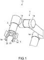
- Fig. 1 is a diagram showing a robot hand 10 according to a first embodiment of the present technology. As shown in Fig. 1 , the robot hand 10 includes an arm portion 1, a wrist portion 2, and a hand portion 3.
- the arm portion 1 has a plurality of joint portions 1a, and driving of the joint portions 1a can move the hand portion 3 to an arbitrary position.
- the wrist portion 2 is rotatably connected to the arm portion 1, and its rotation can rotate the hand portion 3.
- the hand portion 3 has two finger portions 3a opposite to each other, and driving of the two finger portions 3a can grip the target object between the two finger portions 3a. It should be noted that although the hand portion 3 is configured to have the two fingers in the example shown in Fig. 1 , the number of finger portions 3a can be modified as appropriate, e.g., three or four.
- the sensor 20 is capable of detecting a force applied in a perpendicular direction (Z-axis direction) to the sensor 20 and is also capable of detecting a force applied in an in-plane direction (X-axis direction and Y-axis direction) to the sensor 20. That is, the sensor 20 is a three-axis sensor capable of detecting a force corresponding to three-axis directions. It should be noted that the configuration of the sensor 20 will be described later with reference to Fig. 2 and the like.
- the robot hand 10 is driven under the control of a control apparatus (not shown).
- the control apparatus may be a dedicated apparatus in the robot hand 10 or may be a generally-used apparatus.
- the control apparatus may be, for example, a personal computer (PC), a mobile phone (including a smartphone), a server apparatus in a network, or the like.
- the control apparatus includes a control unit, a storage unit, and the like.
- the control unit is, for example, a central processing unit (CPU), and controls driving of the respective parts of the robot hand 10 on the basis of a program stored in the storage unit.
- the control unit acquires information about forces in the three-axis directions detected by the sensors 20, and controls driving of the hand portion 3 so as to grip the target object stably with a suitable gripping force on the basis of this information about the force.
- the storage unit includes a nonvolatile memory in which various programs and data necessary for processing of the control unit is stored and a volatile memory that is used as a working area for the control unit.
- the various programs may be read from a portable recording medium such as a semiconductor memory or may be downloaded from a server apparatus in a network.
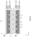
- Fig. 2 is a cross-sectional view of the sensor 20 as it is viewed from the side.
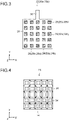
- Fig. 3 is a plan view showing sensor electrode layers 30 in the sensor 20.
- Fig. 4 is a diagram of a separation layer 23 in the sensor 20 as it is viewed from the rear side.
- the X-axis direction and the Y-axis direction are the in-plane direction parallel to a sensing surface of the sensor 20, and the Z-axis direction is a perpendicular direction perpendicular to the sensing surface.
- the upper side corresponds to a front side on which an external force is applied and the lower side corresponds to a rear side opposite thereto.
- the sensor 20 generally has a rectangular plate-like shape in a plan view.
- the shape of the sensor 20 in the plan view only needs to be set as appropriate depending on a shape of a portion in which the sensor 20 is disposed, and the shape of the sensor 20 in the plan view is not particularly limited.
- the shape of the sensor 20 in the plan view may be a polygonal shape, a circular shape, an elliptical shape, or the like other than the rectangular shape.
- the sensor 20 includes a sensor unit 21 having the first pressure sensor 22a on the front side and the second pressure sensor 22b on the rear side and the separation layer 23 interposed between a first pressure sensor 22a and a second pressure sensor 22b. That is, the sensor 20 has a laminate structure in which the second pressure sensor 22b, the separation layer 23, and the first pressure sensor 22a are stacked in order from the side of the lower layer in the perpendicular direction. It should be noted that the two pressure sensors 22a and 22b will be simply referred to as pressure sensors 22 in a case where the two pressure sensors 22a and 22b are not particularly distinguished from each other in the description below.
- a viscoelastic layer (not shown) having hardness similar to that of human skin, for example.
- the viscoelastic layer transmits the external force to the sensor 20 while deforming in accordance with the external force.
- the sensor unit 21 On the basis of the pressure center position (pressure detection position) in the in-plane direction based on the first pressure sensor 22a and the pressure center position (pressure detection position) in the in-plane direction based on the second pressure sensor 22b, the sensor unit 21 detects a force (shear force Fs) applied in the in-plane direction to the sensor 20. Further, on the basis of a pressure value detected by the first pressure sensor 22a, the sensor unit 21 detects a force (load Fz) applied from the upper side in the perpendicular direction to the sensor 20.
- the sensor unit 21 may detect a force applied from the upper side in the perpendicular direction to the sensor 20. That is, typically, on the basis of the pressure value detected by at least the first pressure sensor 22a of the first pressure sensor 22a and the second pressure sensor 22b, the sensor unit 21 only needs to be configured to detect a force applied from the upper side in the perpendicular direction.
- the first pressure sensor 22a and the second pressure sensor 22b are disposed opposite to each other in the perpendicular direction.
- the first pressure sensor 22a may have a laminate structure in which a sensor electrode layer 30a, a deformation layer 27a, and an electrode film layer 26a are stacked in order from the side of the lower layer in the perpendicular direction.
- the second pressure sensor 22b has a laminate structure in which an electrode film layer 26b, a deformation layer 27b, and a sensor electrode layer 30b are stacked in order from the side of the lower layer in the perpendicular direction.
- the first pressure sensor 22a and the second pressure sensor 22b are disposed so that they are inverted in the upper and lower directions. Therefore, the first pressure sensor 22a and the second pressure sensor 22b are configured so that the sensor electrode layers 30 of both are disposed on a side of the separation layer 23. It should be noted that the first pressure sensor 22a and the second pressure sensor 22b have basically similar configurations except for the point that they are inverted in the upper and lower directions. It should be noted that the first pressure sensor 22a and the second pressure sensor 22b may be disposed so that they are not inverted in the upper and lower directions.
- Each of the sensor electrode layers 30 is constituted by a flexible printed circuit or the like.
- the sensor electrode layer 30 includes a rectangular main body 36 in the plan view and an extending portion 37 extended outward from the main body 36.
- the extending portion 37 is provided to output information about a pressure detected by the pressure sensor 22 to the control unit or the like. It should be noted that the shape of the sensor electrode layer in the plan view is not limited to the rectangle, and can be modified as appropriate.
- the sensor electrode layer 30 includes a base material 29 having flexibility and a plurality of sensing portions 28 provided inside the base material 29.
- polymer resin such as polyethylene terephthalate, polycarbonate, and acrylic resin is used.
- the sensing portions 28 are regularly arranged at predetermined intervals vertically and horizontally (vertical: Y-axis direction, horizontal: X-axis direction). In the example shown in Fig. 3 , the number of sensing portions 28 is 5 x 5 (vertical x horizontal), 25 in total. It should be noted that the number of sensing portions 28 can be modified as appropriate.
- the sensing portions 28 are capacitive sensors capable of detecting changes in distance to a reference electrode layer 25 of an electrode film layer 26 as changes in capacitance.
- the sensing portions 28 has, for example, a comb teeth-like pulse electrode (not shown) and a comb teeth-like sense electrode.
- the comb teeth-like pulse electrode and the comb teeth-like sense electrode are disposed so that the comb teeth face each other, and also disposed so that one comb teeth are inserted into gaps between the other comb teeth.
- the type of the sensing portions 28 is not particularly limited, and any type may be used.
- Each of the electrode film layers 26 has flexibility and includes a film layer 24 and a reference electrode layer 25 provided on a side of one surface of the film layer 24 (on a side of a surface of a deformation layer 27).
- the reference electrode layer 25 is a so-called grounding electrode and has a ground potential.
- the electrode film layers 26 has a thickness of, for example, approximately 10 um to 100 um. Further, the reference electrode layer 25 has a thickness of, for example, approximately 0.05 um to 0.5 ⁇ m.
- polymer resin such as polyethylene terephthalate, polycarbonate, and acrylic resin is used.
- an inorganic electrically conductive material an organic electrically conductive material, an electrically conductive material including both an inorganic electrically conductive material and an organic electrically conductive material, or the like is used.
- examples of the inorganic electrically conductive material can include metal such as aluminum, copper, and silver, alloy such as stainless steel, and metal oxide such as oxide zinc and oxide indium.
- examples of the organic electrically conductive material can include a carbon material such as carbon black and carbon fibers and electrically conductive polymer such as substituted or non-substituted polyaniline and polypyrrole. It should be noted that regarding the material, any material may be used as long as it is an electrically conductive material.
- the reference electrode layer 25 is formed on the film layer 24, for example, by a technique such as vapor deposition, sputtering, bonding, and coating. It should be noted that the film layer 24 can also be omitted, and in this case, the reference electrode layer 25 is constituted by a metal thin plate of stainless steel, aluminum, or the like, electrically conductive fibers, electrically conductive non-woven fabric, or the like.
- the deformation layer 27 is interposed between the sensor electrode layers 30 and the electrode film layers 26 (reference electrode layer 25).
- the deformation layer 27 has a thickness of, for example, approximately 50 um to 300 ⁇ m.
- the deformation layer 27 is configured to be elastically deformable in accordance with the external force.
- the reference electrode layer 25 moves closer to the sensor electrode layer 30 while the deformation layer 27 elastically deforms in accordance with the external force.
- the sensing portions 28 the capacitance between the pulse electrode and the sense electrode changes, and therefore the sensing portions 28 are capable of detecting this change in capacitance as a pressure value.
- the thickness of the deformation layer 27 is more than 100 um and 1000 um or less and the weight per unit area of the deformation layer 27 is 50 mg/cm 2 or more. Setting the thickness and the weight per unit area of the deformation layer 27 to be in these ranges can improve the detection sensitivity of the pressure sensor 22 in the perpendicular direction.
- a lower-limit value of the thickness of the deformation layer 27 is not particularly limited as long as it is larger than 100 um, and the lower-limit value may be, for example, 150 um or more, 200 um or more, 250 um or more, 300 um or more, or the like.
- an upper-limit value of the thickness of the deformation layer 27 is not particularly limited as long as it is 1000 um or less, and the upper-limit value may be, for example, 950 um or more, 900 um or less, 850 um or less, 800 or less, or the like.
- the thickness of the deformation layer 27 is determined in the following manner. First of all, a cross-section is produced by working the pressure sensor 22 by a focused ion beam (IB) method or the like, and a cross-section image (hereinafter, referred to as "cross-section SEM image") is captured by the use of a scanning electron microscope (SEM). Next, a point is randomly selected from the deformation layer 27 in the cross-section SEM image, and the thickness of the deformation layer 27 is measured at the point.
- IB focused ion beam
- SEM image scanning electron microscope
- An upper-limit value of the weight per unit area of the deformation layer 27 is not particularly limited as long as it is 50 mg/cm 2 or more, and the upper-limit value may be, for example, 45 mg/cm 2 or less, 40 mg/cm 2 or less, 35 mg/cm 2 or less, or the like.
- a lower-limit value of the weight per unit area of the deformation layer 27 is not particularly limited, and the lower-limit value may be, for example, 3 mg/cm 2 or more, 5 mg/cm 2 or more, 7 mg/cm 2 or more, 10 mg/cm 2 or more, or the like.
- the deformation layer 27 includes a porous layer.
- the porous layer may be a fiber layer.
- the fiber layer is, for example, non-woven fabric or woven fabric. Fibers contained in the fiber layer may be nanofibers or may be thicker fibers. It should be noted that in a case where the deformation layer 27 is a nanofiber layer, the sensitivity of the pressure sensor 22 in the perpendicular direction can be further improved.
- the fibers may include polymer resin or may include inorganic material. It should be noted that in a case where the fibers include polymer resin, the sensitivity of the pressure sensor 22 in the perpendicular direction can be further improved.
- the porous layer includes a three-dimensional stereoscopic structure (irregular network structure like non-woven fabric) formed from a fibrous structure, and a plurality of clearances (thin holes) may be provided. Since the porous layer includes the three-dimensional stereoscopic structure, a structure having high porosity can be produced, and a reduction in the film thickness is also easy.
- the fibrous structure is a fibrous matter having a sufficient length with respect to a fiber diameter (diameter).
- the porous layer is configured by a plurality of fibrous structures assembling and randomly overlapping each other.
- the porous layer may be configured by a single fibrous structure randomly twisting.
- a porous layer of a single fibrous structure and porous layers of a plurality of fibrous structures may mix.
- the fibrous structure extends in a straight line shape, for example.
- the fibrous structure may have any shape, and may be curly or may be bent part way, for example. Alternatively, the fibrous structure may branch part way.
- a minimum fiber diameter of the fibrous structure is, for example, 500 nm or less, 300 nm or less, or the like.
- An average fiber diameter is, for example, 0.1 um or more and 10 um or less, or the like. Reducing the average fiber diameter increases the hole diameter of thin holes.
- the average fiber diameter can be measured by microscope observation using a scan-type electronic microscope or the like for example.
- the average length of the fibrous structure is arbitrary.
- the fibrous structure is formed by, for example, a phase separation method, a phase inversion method, an electrospinning method, a melt spinning method, a wet spinning method, a dry spinning method, a gel spinning method, a sol-gel method, a spraying method, or the like. Using such a method can easily and stably form a fibrous structure having a sufficient length with respect to the fiber diameter.
- the fibrous structure is formed from at least one of polymer material or inorganic material, and is constituted especially by nanofibers.
- the nanofibers have a fiber diameter of 1 nm or more and 1000 nm or less and are fibrous matters having a length equal to or larger than a length 100 times as large as the fiber diameter.
- the fibrous structure constituted by the nanofibers may be formed by the electrospinning method. Using the electrospinning method can easily and stably form a fibrous structure having a small fiber diameter.
- the deformation layer 27 may be constituted by a patterning structure having a pole structure, for example.
- a patterning structure having a pole structure, for example.
- a variety of structures such as a matrix pattern, a stripe pattern, a mesh pattern, a radial pattern, a geometric pattern, and a spiral pattern can be employed as the patterning structure.
- the separation layer 23 is fixed between the first pressure sensor 22a and the second pressure sensor 22b via an adhesive layer (not shown).
- the separation layer 23 is deformable in accordance with the external force.
- the separation layer 23 has gap portions 33 and includes a plurality of pole portions 34 that is formed by the gap portions 33 and extends in the perpendicular direction.
- the gap portions 33 are provided in the shape of grooves not penetrating the separation layer 23 in the perpendicular direction on a back surface side of the separation layer 23 (on a side of the second pressure sensor 22b).
- the separation layer 23 includes a filling layer 31 (first layer) of a filling structure without the gap portions 33 on the front side (on a side of the first pressure sensor 22a). Further, the separation layer 23 includes a pole layer 32 (second layer) having the gap portions 33 and having the plurality of pole portions 34 formed by the gap portions 33 on the rear side (on the side of the second pressure sensor 22b).
- Each of the plurality of pole portions 34 has a shape the thickness of which is not constant and different in the perpendicular direction.
- the plurality of pole portions 34 is formed to become gradually thinner from the front side (on the side of the first pressure sensor 22a) to the rear side (on the side of the second pressure sensor 22b) in the perpendicular direction.
- each of the plurality of pole portions 34 has an inverted truncated square pyramid shape.
- the pole portion 34 may be formed in a shape such as an inverted truncated cone shape, an inverted triangular cone shape, an inverted pentagonal frustum shape, and an inverted hexagonal frustum shape.
- the pole portions 34 are arranged vertically and horizontally regularly.
- the pole portions 34 are respectively provided at positions corresponding to the sensing portions 28 in the perpendicular direction, and therefore the gap portions 33 for forming the pole portions 34 are provided at positions not corresponding to the sensing portions 28 in the perpendicular direction.
- the number of pole portions 34 is the same as the number of sensing portions 28b in the second pressure sensor 22b, and is 5 x 5 (vertical x horizontal), 25 in total. It should be noted that the number of pole portions 34 can be modified as appropriate.
- the thickness of the separation layer 23 is, for example, approximately 1000 um to 5000 um.
- the height of the pole portion 34 in the perpendicular direction i.e., a depth of the gap portion 33 in the groove shape
- the height of the pole portion 34 in the perpendicular direction is 20% or more, 25% or more, 30% or more, 35% or more, 40% or more, 45% or more, or the like of the thickness of the separation layer 23.
- the height of the pole portion 34 is not problematic if it is tall (e.g., 1000 of the thickness of the separation layer 23), but there is a possibility that the pole portion 34 cannot effectively function if it is too short (e.g., lower than 20% of the thickness of the separation layer 23).
- An area (in the in-plane direction) of lower surfaces of the pole portions 34 (portions held in contact with the second pressure sensor 22b) is set in accordance with the sensing portions 28b of the second pressure sensor 22, and for example, is substantially the same as the area of the sensing portions 28b.
- the separation layer 23 is typically constituted by viscoelastic material having viscoelastic characteristics.
- a material that is used for the separation layer 23 can include silicone gel, urethane gel, synthetic rubber, and foam.
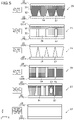
- Fig. 5 is a diagram showing the respective examples of the shape of the separation layer 23.
- Fig. 5 shows six patterns of shapes A to F as to the shape of the separation layer 23. It should be noted that Fig. 5 is depicted simplifying the first pressure sensor 22a and the second pressure sensor 22b.
- the shape A is a shape already described with reference to Figs. 2 and 4 .
- the gap portions 33 are provided in the shape of grooves not penetrating the separation layer 23 in the perpendicular direction on the back surface side of the separation layer 23 (on the side of the second pressure sensor 22b). Further, in the shape B, as in the shape A, a two-layer structure of the filling layer 31 and the pole layer 32 is provided.
- the thickness of the pole portion 34 is different in the perpendicular direction while in the shape B, the thickness of the pole portion 34 is the same in the perpendicular direction.
- the shape of the pole portion 34 includes a quadratic prism shape. It should be noted that the shape of the pole portion 34 may be formed in a shape such as a columnar shape, a triangular prism shape, a pentagonal prism shape, and a hexagonal prism shape.
- the pole portions 34 in the shape A are typically provided at positions corresponding to the sensing portions 28b of the second pressure sensor 22b in the perpendicular direction. It should be noted that the same applies to the shapes C to E.
- the gap portions 33 have the shape of the grooves not penetrating the separation layer 23 in the perpendicular direction while in the shape C, the gap portions 33 have the shape of the holes penetrating the separation layer 23 in the perpendicular direction.
- the height of the pole portion 34 is taller than those of the shape A and the shape B and the height of the pole portion 34 is identical to the thickness of the separation layer 23. That is, the height of the pole portion 34 is 100% with respect to the thickness of the separation layer 23.
- the separation layer 23 has the two-layer structure of the filling layer 31 and the pole layer 32 while in the shape C, the filling layer 31 is not provided and the separation layer 23 has a single-layer structure of the pole layer 32.
- the shape of the pole portion 34 is an inverted truncated square pyramid.
- the shape of the pole portion 34 may be an inverted truncated cone shape, an inverted triangular cone shape, an inverted pentagonal frustum shape, an inverted hexagonal prism shape, or the like.
- the gap portions 33 have the shape of holes penetrating the separation layer 23 in the perpendicular direction. Further, in the shape D, as in the shape C, the height of the pole portion 34 is identical to the thickness of the separation layer 23 and the height of the pole portion 34 is 100% with respect to the thickness of the separation layer 23.
- the thickness of the pole portion 34 is different in the perpendicular direction while in the shape D, the pole portion 34 has the same thickness in the perpendicular direction.
- the shape of the pole portion 34 includes a quadratic prism shape. It should be noted that the shape of the pole portion 34 may be formed in a shape such as a columnar shape, a triangular prism shape, a pentagonal prism shape, and a hexagonal prism shape.
- the shape E shows an example of a combination of the shapes A to D and the like. That is, the shapes A to D and the like can be combined as appropriate.
- the pole portion 34 on the leftmost-hand side corresponds to the pole portion 34 in the shape C.
- Four other pole portions 34 correspond to the pole portions 34 in the shape D but they have different thicknesses.
- the second pole portion 34 from the right has a circular gap portion 33 at a center position in the perpendicular direction (the gap portion 33 is in contact with neither the first pressure sensor 22a nor the second pressure sensor 22b).
- the shape F is a Comparative Example without the gap portions 33, and a separation layer 23' is a filling structure as the whole.
- Fig. 6 is a diagram of the separation layer 23 as it is viewed from the back surface side, and is a diagram showing respective patterns of the shape of the pole portions 34 in the plan view.
- the uppermost diagram in Fig. 6 shows a state in which the pole portions 34 have a quadratic prism shape.
- the second diagram from above in Fig. 6 shows a state in which the pole portions 34 have a hexagonal prism shape (honeycomb teeth structure).
- the third diagram from above in Fig. 6 shows a state in which the pole portions 34 in different shapes (cylinder, quadrangular prism, a triangular prism, and the like) are combined. It should be noted that the lowermost diagram in Fig. 6 corresponds to a Comparative Example without the gap portions 33.
- Fig. 7 is a diagram representing a state in which load Fz is applied downward in the perpendicular direction to the sensor 20 as a model.
- Fig. 8 is a diagram representing a state in which the shear force Fs is applied in the in-plane direction as a model with the load Fz in the perpendicular direction applied to the sensor 20. It should be noted that in Figs. 7 and 8 , contour lines of detected pressures are shown as the broken-line circular shapes.
- a pressure center position P in the in-plane direction that is detected by the first pressure sensor 22a is identical to the pressure center position Q in the in-plane direction that is detected by the second pressure sensor 22b.
- the pressure center position means a position in the in-plane direction that corresponds to the highest pressure in a detected pressure distribution.
- the pressure center position P in the in-plane direction that is detected by the first pressure sensor 22a is not identical to the pressure center position Q in the in-plane direction that is detected by the second pressure sensor 22b.
- the separation layer 23 deforms in accordance with the shear force Fs applied in the in-plane direction. At this time, the separation layer 23 generates shear stress ⁇ corresponding to the shear force Fs.
- the rigidity rate of the separation layer 23 is denoted by G and the thickness of the separation layer 23 is denoted by t.
- the rigidity rate G of the separation layer 23 is known on the right side in the equation. Therefore, when a difference d between the pressure center position P in the in-plane direction of the first pressure sensor 22a and the pressure center position Q in the in-plane direction of the second pressure sensor 22b is determined on the basis of them, shear stress Fs, i.e., a force in the in-plane direction can be detected.
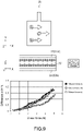
- Fig. 9 is a diagram showing the evaluation of the variation in the detection sensitivity of the shear force Fs in the separation layer 23' according to the comparative example.
- a diagram on the upper side of Fig. 9 is a top view showing the sensor 20 according to the comparative example, and shows points and directions in the in-plane direction in which the shear force Fs is applied.
- a diagram at the center of Fig. 9 is a side view showing the sensor 20 according to the comparative example.
- the separation layer 23' according to the comparative example does not have the gap portions 33 and is the filling structure as a whole.
- the load Fz in the perpendicular direction was applied and the shear force Fs was applied in the X-axis direction to a point A near the upper left angle, a point B near the lower left angle, and a point C at the center in the in-plane direction of the sensor 20 at different timings.
- a diagram on the lower side of Fig. 9 is a diagram when the shear force Fs was changed and the difference d between the pressure center position P and the pressure center position Q was measured at each of the point A, the point B, and the point C.
- the difference d is smaller at the point C near the center as compared to the point A and the point B near the corners.
- shear force Fs is calculated on the basis of each difference d.
- the shear force Fs determined for the point C is smaller than the shear force Fs determined for each of the point A and the point B. In this manner, in the comparative example, the detection sensitivity of the shear force Fs at the respective points in the in-plane direction is different.
- the separation layer 23' has larger shear stress ⁇ with respect to the shear force Fs as compared to that near a periphery in the in-plane direction, and it is unlikely to deform against the shear force Fs.
- the separation layer 23' has smaller shear stress ⁇ with respect to the shear force Fs as compared to that near the center in the in-plane direction, and it is likely to deform against the shear force Fs.
- the gradient of the graph shows the detection sensitivity of the shear force Fs at each point. That is, as the gradient becomes larger, the detection sensitivity of the shear force Fs becomes better, and as the gradient becomes smaller, the detection sensitivity of the shear force Fs becomes worse.
- the detection sensitivity of the shear force Fs is worse as compared to the point A and the point B near the corners. Further, at the point A and the point B near the corners, the detection sensitivity of the shear force Fs is relatively high as compared to the point C near the center, but this detection sensitivity is insufficient as the detection sensitivity of the shear force Fs. That is, in the comparative example, the detection sensitivity of the shear force Fs itself is bad.
- the pressure detection sensitivity of the second pressure sensor 22b is bad as the separation layer 23' is the filling structure as a whole. That is, in the comparative example, since the separation layer 23' is the filling structure as a whole, when the load Fz in the perpendicular direction is applied, the entire separation layer 23' serves as a buffer layer, and the force is unlikely to be transmitted to the second pressure sensor 22b. Therefore, the position of the pressure center position Q that is detected by the second pressure sensor 22b is inaccurate, and there is a possibility that the shear force Fs cannot be accurately measured.
- the comparative example has the following problems 1 to 3.
- the gap portions 33 are formed in the separation layer 23 and the separation layer 23 has a predetermined shape (e.g., a shape having the pole portions 34).
- Fig. 10 is a diagram showing the evaluation of the variation in the detection sensitivity of the shear force Fs in the separation layer 23 according to the present embodiment.
- a diagram on the upper side of Fig. 10 is a top view showing the sensor 20 according to the present embodiment, and shows points and directions in the in-plane direction in which the shear force Fs is applied.
- a diagram at the center of Fig. 10 is a side view showing the sensor 20 according to the present embodiment.
- the separation layer 23 in the shape B was used as the separation layer 23 according to the present embodiment.
- the separation layer 23 in the shape B has a two-layer structure of the filling layer 31 on the front side and the pole layer 32 on the rear side with the gap portions 33 in the shape of the grooves. Further, the pole portion 34 in the pole layer 32 has a quadratic prism shape.
- the diagram on the lower side of Fig. 10 is a diagram when the shear force Fs was changed and the difference d between the pressure center position P and the pressure center position Q was measured at each of the point A, the point B, and the point C.
- the gradient of the graph at each point in the present embodiment is larger than the gradient of the graph at each point according to the comparative example. It means that in the present embodiment, the detection sensitivity of the shear force Fs is higher than that of the comparative example.
- the detection sensitivity of the shear force Fs is uniform in the in-plane direction and the detection sensitivity of the shear force Fs is improved is that the gap portions 33 are provided in the separation layer 23. That is, in the present embodiment, since deformability (shear stress ⁇ ) of the separation layer 23 against the shear force Fs at each point in the in-plane direction is uniform due to the provision of the gap portions 33 in the separation layer 23, the detection sensitivity of the shear force Fs is uniform in the in-plane direction in the present embodiment.
- the gap portions 33 are provided. Therefore, when the shear force Fs is applied, the separation layer 23 locally deforms at a position corresponding to a point in the in-plane direction at which the shear force Fs is generated, and the deformation is not transmitted so much to a portion other than the local portion.
- the local deformability (shear stress ⁇ ) is uniform irrespective of the point in the in-plane direction. Therefore, in the present embodiment, the detection sensitivity of the shear force Fs is uniform in the in-plane direction.
- the separation layer 23 since the gap portions 33 are provided in the separation layer 23, the separation layer 23 easily deforms against the shear force Fs at each point in the in-plane direction (the shear stress ⁇ is smaller). Thus, the detection sensitivity of the shear force Fs is improved.
- the pole portions 34 formed by the gap portions 33 are provided at the positions corresponding to the sensing portions 28 of the second pressure sensor 22b. Therefore, when the load Fz in the perpendicular direction is applied to the sensor 20, the pole portions 34 locally push the positions corresponding to the sensing portions 28 in the second pressure sensor 22b, and therefore the force can be efficiently transmitted to the second pressure sensor 22b. Therefore, if the load Fz in the perpendicular direction is small, the pressure center position Q can be accurately detected by the second pressure sensor 22b, and the shear force Fs can be accurately measured.
- the pole layer 32 may be constituted by a relatively hard material as compared to the filling layer 31.
- the pole portions 34 in the relatively hard pole layer 32 locally push the positions corresponding to the sensing portions 28 in the second pressure sensor 22b, and therefore the force can be more efficiently transmitted in the second pressure sensor 22b.
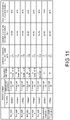
- FIG. 11 is a diagram showing the respective examples and the respective comparative examples of the separation layer 23.
- the sensors 20 including the separation layers 23 different in thickness, shape, and the like were prepared, and with respect to each of the sensors 20, the detection sensitivity of the shear force Fs in the in-plane direction, the variation in the detection sensitivity of the shear force Fs in the in-plane direction, and the resolution of the detection sensitivity of the shear force Fs in the in-plane direction were respectively evaluated.
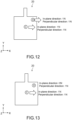
- Fig. 12 is a diagram showing a state when the detection sensitivity of the shear force Fs and a variation in the detection sensitivity of the shear force Fs were evaluated.
- the detection sensitivity (S/N) of the shear force Fs was measured by applying, through a keystroke element with ⁇ 6 in an evaluation apparatus, the shear force Fs of 1N in the in-plane direction in a state in which the load Fz of 1N is applied downward in the perpendicular direction with respect to the point C at the center. That is, the detection sensitivity of the shear force Fs for the point C at the center was used as a representative of the detection sensitivity of the sensor 20.
- the detection sensitivity (S/N) of the shear force Fs was measured by applying, through the keystroke element with ⁇ 6 in the evaluation apparatus, the shear force Fs of 1N in the in-plane direction in a state in which the load Fz of 1N is applied downward in the perpendicular direction with respect to the point D near the right corner.
- Fig. 13 is a diagram showing a state when the resolution of the detection sensitivity of the shear force Fs in the in-plane direction was evaluated.
- the load Fz of 1N is applied through the keystroke element with ⁇ 6 in the evaluation apparatus downward in the perpendicular direction at the point C at the center and the point D near the right corner at the same time.
- the shear force Fs of 1N is applied in the in-plane direction only at the point C at the center.
- the resolution is higher as it is closer to 0%.
- the resolution of the detection sensitivity of the shear force Fs in the in-plane direction is, in a case where it is necessary to detect the shear force Fs at two or more points, an indication as to whether, when the shear force Fs is applied to a certain point, the shear force Fs can be properly detected only at that point while the shear force Fs does not affect the other peripheral point(s).
- Example 1 the thickness of the separation layer 23 was 2000 ⁇ m, and silicone gel having hardness that was penetration of 100 degrees was used as the material of the separation layer 23. Further, in Example 1, the separation layer 23, which was the separation layer 23 in the shape D (see Fig. 5 ), in which the pole portions 34 were arranged in the form of vertically and horizontally 3 x 3 was used. It should be noted that as for the material of the separation layer 23, the same material was used in the respective examples and the respective comparative examples (silicone gel having the hardness that was penetration of 100 degrees).
- Example 1 the detection sensitivity of the shear force Fs was 4.5, and the variation in the detection sensitivity of the shear force Fs in the in-plane direction was 130%. Further, in Example 1, the resolution of the detection sensitivity of the shear force Fs in the in-plane direction was 50%.
- Example 2 the thickness of the separation layer 23 was 4000 um. Further, in Example 2, the separation layer 23, which was the separation layer 23 in the shape D (see Fig. 5 ), in which the pole portions 34 were arranged in the form of vertically and horizontally 3 x 3 was used.
- Example 2 the detection sensitivity of the shear force Fs was 7.5, and the variation in the detection sensitivity of the shear force Fs in the in-plane direction was 130%. Further, in Example 2, the resolution of the detection sensitivity of the shear force Fs in the in-plane direction was 50%.
- Example 2 comparing Example 1 with Example 2, their separation layers 23 have the same material and shape and the separation layers 23 have different thicknesses.
- the detection sensitivity of the shear force Fs is higher than Example 1.
- Example 3 the thickness of the separation layer 23 was 4000 um. Further, in Example 3, the separation layer 23, which was the separation layer 23 in the shape C (see Fig. 5 ), in which the pole portions 34 were arranged in the form of vertically and horizontally 3 x 3 was used.
- Example 3 the detection sensitivity of the shear force Fs was 7.5, and the variation in the detection sensitivity of the shear force Fs in the in-plane direction was 130%. Further, in Example 3, the resolution of the detection sensitivity of the shear force Fs in the in-plane direction was 50%.
- Example 2 comparing Example 2 with Example 3, their separation layers 23 have the same thickness and material and the separation layers 23 have different shapes (shape D, shape C).
- the detection sensitivity, variation, and resolution of the shear force Fs each have the same value. Therefore, it can be seen that the separation layers 23 in the shape D and the shape C have substantially the same performance.
- Example 4 the thickness of the separation layer 23 was 4000 um. Further, in Example 4, the separation layer 23, which was the separation layer 23 in the shape B (see Fig. 5 ), in which the pole portions 34 were arranged in the form of vertically and horizontally 3 x 3 was used.
- Example 4 the detection sensitivity of the shear force Fs was 10.0, and the variation in the detection sensitivity of the shear force Fs in the in-plane direction was 100%. Further, in Example 4, the resolution of the detection sensitivity of the shear force Fs in the in-plane direction was 25%.
- Example 4 comparing Example 4 with Example 2 and Example 3, their separation layers 23 have the same thickness and material and the separation layers 23 have different shapes (shape B, shape D, and shape C).
- the detection sensitivity, variation, and resolution of the shear force Fs are respectively enhanced. Therefore, it can be seen that the separation layer 23 in the shape B has higher performance than the separation layers 23 in the shape D and the shape C.
- the separation layer 23 in the shape B has improved performance as compared to the separation layers 23 in the shape D and the shape C is that the separation layer 23 in the shape B has the two-layer structure including the filling layer 31 and the pole layer 32. That is, since in the shape B, the filling layer 31 sufficiently supports the first pressure sensor 22a from below, the first pressure sensor 22a is capable of properly detecting a pressure (pressure center position) based on the external force. In addition, since in the shape B, the pole portions 34 of the pole layer 32 locally push the second pressure sensor 22b, the second pressure sensor 22b is capable of properly detecting a pressure (pressure center position) based on the external force.
- Example 5 the thickness of the separation layer 23 was 4000 um. Further, in Example 5, the separation layer 23, which was the separation layer 23 in the shape A (see Fig. 5 ), in which the pole portions 34 were arranged in the form of vertically and horizontally 3 x 3 was used.
- Example 5 the detection sensitivity of the shear force Fs was 10.0, and the variation in the detection sensitivity of the shear force Fs in the in-plane direction was 100%. Further, in Example 5, the resolution of the detection sensitivity of the shear force Fs in the in-plane direction was 25%.
- Example 4 comparing Example 4 with Example 5, their separation layers 23 have the same thickness and material and the separation layers 23 have different shapes (shape B, shape A).
- the detection sensitivity, variation, and resolution of the shear force Fs each have the same value. Therefore, it can be seen that the separation layers 23 in the shape B and the shape A have substantially the same performance. It should be noted that the separation layers 23 in the shape B and the shape A both have the two-layer structure including the filling layer 31 and the pole layer 32.
- Example 6 the thickness of the separation layer 23 was 4000 um. Further, in Example 6, the separation layer 23, which was the separation layer 23 in the shape A (see Fig. 5 ), in which the pole portions 34 were arranged in the form of vertically and horizontally 9 x 9 was used.
- Example 6 the detection sensitivity of the shear force Fs was 10.0, and the variation in the detection sensitivity of the shear force Fs in the in-plane direction was 100%. Further, in Example 6, the resolution of the detection sensitivity of the shear force Fs in the in-plane direction was 10%.
- Example 5 comparing Example 5 with Example 6, their separation layers 23 have the same thickness, material, and shape, and the finesse of the gap portions in the separation layers 23 is different (the number of divisions of the separation layer 23 is different).
- Example 6 as compared to Example 5, the resolution of the shear force Fs is improved. It is because the shear force Fs at a certain point is more unlikely to be transmitted to a peripheral point due to the provision of the finer gap portions 33 in the separation layer 23 in Example 6 as compared to Example 5.
- the thickness of the separation layer 23 was 2000 um. Further, in Comparative Example 1, the separation layer 23' in the shape F (see Fig. 5 ), i.e., the separation layer 23' that was entirely the filling structure was used.
- the thickness of the separation layer 23 was 4000 um. Further, in Comparative Example 2, the separation layer 23' in the shape F (see Fig. 5 ), i.e., the separation layer 23' that was entirely the filling structure was used.
- the detection sensitivity of the shear force Fs was 5.0, and the variation in the detection sensitivity of the shear force Fs in the in-plane direction was 200%. Further, in Comparative Example 2, the resolution of the detection sensitivity of the shear force Fs in the in-plane direction was 80%.
- Comparative Example 2 comparing Comparative Example 1 with Comparative Example 2, their separation layers 23 have the same material and shape and the separation layers 23 have different thicknesses.
- Comparative Example 2 since the thickness of the separation layer 23 is larger than Comparative Example 1, the detection sensitivity, variation, and resolution of the shear force Fs are each improved than Comparative Example 1, but it is insufficient as the performance.
- the resolution in the in-plane direction of the shear force Fs is improved is that the gap portions 33 are provided in the separation layer 23. That is, since the gap portions 33 are provided in the separation layer 23, when the shear force Fs is applied to the sensor 20, the separation layer 23 locally deforms at the position corresponding to the point in the in-plane direction at which the shear force Fs is generated, and the deformation is not transmitted so much to a portion other than the local portion. Therefore, the resolution is improved.
- the first pressure sensor 22a and the second pressure sensor 22b each have a three-layer structure in which the sensor electrode layer 30, the deformation layer 27, and the electrode film layer 26 (reference electrode layer 25) are stacked.
- an improvement in the detection sensitivity to the load Fz in the perpendicular direction is achieved by reducing the thickness of the deformation layer 27 and making the deformation layer 27 softer.
- the thickness of the deformation layer 27 is more than 100 um and 1000 um or less and the weight per unit area of the deformation layer 27 is 50 mg/cm 2 or more.
- Fig. 14 is a diagram showing the respective examples and the respective comparative examples of the deformation layer 27 (see Fig. 2 ).
- Fig. 14 shows the thickness, weight per unit area, commodity name, and material of the deformation layer 27 in the respective examples and the respective comparative examples. Further, in Fig. 14 , the detection sensitivity (S/N) of the sensor 20 in the perpendicular direction when the load Fz of 1 kPa, 100 kPa was applied to the sensor 20 downward in the perpendicular direction is shown.
- the load Fz to the sensor 20 in the perpendicular direction can be determined on the basis of a pressure value detected by the first pressure sensor 22a, and therefore as to the detection sensitivity of the sensor 20 in the perpendicular direction, the detection sensitivity of the first pressure sensor 22a in the perpendicular direction is used for evaluation.
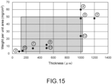
- Fig. 15 is a diagram showing a relationship between the thickness and the weight per unit area of the deformation layer 27 in the respective examples and the respective comparative examples.
- Example 7 the thickness of the deformation layer 27 was 300 um, and the weight per unit area was 7.2 mg/cm 2 . Further, in Example 7, PORON (registered trademark) SS-24DP, which is a foam film including polyurethane, was used as the material of the deformation layer 27.
- Example 7 the detection sensitivity of the sensor 20 in the perpendicular direction when the load Fz of 1 kPa and 100 kPa was applied to the sensor 20 in the perpendicular direction was respectively 3.0 and 80. This detection sensitivity was a high value during a low-pressure time and during a high-pressure time.
- Example 8 the thickness of the deformation layer 27 was 500 um, and the weight per unit area was 12 mg/cm 2 . Further, in Example 8, PORON (registered trademark) SS-24DP, which is a foam film including polyurethane, was used as the material of the deformation layer 27.
- Example 8 the detection sensitivity of the sensor 20 in the perpendicular direction when the load Fz of 1 kPa and 100 kPa was applied to the sensor 20 in the perpendicular direction was respectively 2.5 and 120. This detection sensitivity was a high value during a low-pressure time and during a high-pressure time.
- Example 9 the thickness of the deformation layer 27 was 1000 um, and the weight per unit area was 24 mg/cm 2 . Further, in Example 9, PORON (registered trademark) SS-24DP, which is a foam film including polyurethane, was used as the material of the deformation layer 27.
- Example 9 the detection sensitivity of the sensor 20 in the perpendicular direction when the load Fz of 1 kPa and 100 kPa was applied to the sensor 20 in the perpendicular direction was respectively 2.0 and 150. This detection sensitivity was a high value during a low-pressure time and during a high-pressure time.
- Example 10 the thickness of the deformation layer 27 was 150 um, and the weight per unit area was 4 mg/cm 2 . Further, in Example 10, PORON (registered trademark) SS-15DP, which is a foam film including polyurethane, was used as the material of the deformation layer 27.
- Example 10 the detection sensitivity of the sensor 20 in the perpendicular direction when the load Fz of 1 kPa and 100 kPa was applied to the sensor 20 in the perpendicular direction was respectively 4.0 and 200. This detection sensitivity was a high value during a low-pressure time and during a high-pressure time.
- Example 11 the thickness of the deformation layer 27 was 500 um, and the weight per unit area was 7.5 mg/cm 2 . Further, in Example 11, a nanofiber including polyurethane was used as the material of the deformation layer 27.
- Example 11 the detection sensitivity of the sensor 20 in the perpendicular direction when the load Fz of 1 kPa and 100 kPa was applied to the sensor 20 in the perpendicular direction was respectively 2.0 and 60. This detection sensitivity was a high value during a low-pressure time and during a high-pressure time.
- Example 12 the thickness of the deformation layer 27 was 1000 um, and the weight per unit area was 48 mg/cm 2 . Further, in Example 12, PORON (registered trademark) SR-S-48, which is a foam film including polyurethane, was used as the material of the deformation layer 27.
- Example 12 the detection sensitivity of the sensor 20 in the perpendicular direction when the load Fz of 1 kPa and 100 kPa was applied to the sensor 20 in the perpendicular direction was respectively 1.5 and 80. This detection sensitivity was a high value during a low-pressure time and during a high-pressure time.
- the thickness of the deformation layer 27 was 100 um, and the weight per unit area was 3 mg/cm 2 . Further, in Example 3, Purecell (registered trademark) S010, which is a foam film including polyurethane, was used as the material of the deformation layer 27.
- the detection sensitivity of the sensor 20 in the perpendicular direction when the load Fz of 1 kPa and 100 kPa was applied to the sensor 20 in the perpendicular direction was respectively 2.0 and 20.
- Comparative Example 3 the detection sensitivity when the load Fz of 1 kPa is applied is not problematic, but the detection sensitivity when the load Fz of 100 kPa is applied is too low. That is, in Comparative Example 3, since the thickness of the deformation layer 27 is 100 ⁇ m, which is too small, the deformation amount during a high-pressure time is small and the detection sensitivity is bad. Therefore, in the present embodiment, the thickness of the deformation layer 27 is typically larger than 100 um (also see the fact that a good result was obtained with the thickness of 150 um in Example 10).
- the thickness of the deformation layer 27 was 1000 um, and the weight per unit area was 60 mg/cm 2 . Further, in Example 4, PORON (registered trademark) NU60, which is a foam film including polyurethane, was used as the material of the deformation layer 27.
- the detection sensitivity of the sensor 20 in the perpendicular direction when the load Fz of 1 kPa and 100 kPa was applied to the sensor 20 in the perpendicular direction was respectively 1 or less and 30.
- the detection sensitivity when the load Fz of 1 kPa is applied and the detection sensitivity when the load Fz of 100 kPa is applied are both too low. It is because the weight per unit area is 60 mg/cm 2 and the weight per unit area is too large in Comparative Example 4, so the deformation layer 27 is too hard. Therefore, in the present embodiment, the weight per unit area of the deformation layer 27 typically is 50 mg/cm 2 or more (also see the fact that a good result was obtained with the weight per unit area of 48 mg/cm 2 in Example 12).
- the thickness of the deformation layer 27 was 1200 um, and the weight per unit area was 48 mg/cm 2 . Further, in Example 5, PORON (registered trademark) MS40, which is a foam film including polyurethane, was used as the material of the deformation layer 27.
- the detection sensitivity of the sensor 20 in the perpendicular direction when the load Fz of 1 kPa and 100 kPa was applied to the sensor 20 in the perpendicular direction was respectively 1 or less and 80.
- the detection sensitivity when the load Fz of 100 kPa is applied is not problematic, but the detection sensitivity when the load Fz of 1 kPa is applied is too low. That is, in Comparative Example 5, since the thickness of the deformation layer 27 is 1200 ⁇ m, which is too large, and with the deformation amount during a low-pressure time, the distance between the sensor electrode layer 30 and the reference electrode layer 25 is too long, and the detection sensitivity is bad. Therefore, in the present embodiment, the thickness of the deformation layer 27 typically is 1000 um or less (also see the fact that a good result was obtained with the thickness of 1000 um in Example 9, Example 12).
- the detection sensitivity to the load Fz in the perpendicular direction can be improved.
- the gap portions 33 are provided in the separation layer 23.
- the detection sensitivity of the shear force Fs becomes uniform in the in-plane direction, the detection sensitivity of the shear force Fs is improved, and also the resolution in the in-plane direction of the shear force Fs is improved.
- the separation layer 23 since the gap portions 33 are provided in the separation layer 23, when the shear force Fs is applied, the separation layer 23 locally deforms at the position corresponding to the point in the in-plane direction at which the shear force Fs is generated, and the deformation is not transmitted so much to a portion other than the local portion.
- the local deformability (shear stress ⁇ ) is uniform irrespective of the point in the in-plane direction. Therefore, in the present embodiment, the detection sensitivity of the shear force Fs is uniform in the in-plane direction. Further, in the present embodiment, due to the characteristic that the separation layer 23 locally deforms at the position corresponding to the point in the in-plane direction at which the shear force Fs is applied, the resolution is also improved.
- the separation layer 23 since the gap portions 33 are provided in the separation layer 23, the separation layer 23 easily deforms against the shear force Fs at each point in the in-plane direction (the shear stress ⁇ is smaller), and accordingly, the detection sensitivity of the shear force Fs can be improved.
- the pole portions 34 formed by the gap portions 33 are provided at the positions corresponding to the sensing portions 28 of the second pressure sensor 22b. Therefore, when the load Fz in the perpendicular direction is applied to the sensor 20, the pole portions 34 locally push the positions corresponding to the sensing portions 28 in the second pressure sensor 22b, and therefore the force can be efficiently transmitted to the second pressure sensor 22b. Therefore, if the load Fz in the perpendicular direction is small, the pressure center position Q can be accurately detected by the second pressure sensor 22b, and the shear force Fs can be accurately measured.
- the first pressure sensor 22a is capable of properly detecting a pressure (pressure center position) based on the external force in such a manner that the filling layer 31 sufficiently supports the first pressure sensor 22a from below.
- the second pressure sensor 22b is capable of properly detecting a pressure (pressure center position) based on the external force.
- the pole layer 32 is constituted by a relatively hard material as compared to the filling layer 31, when the load Fz in the perpendicular direction is applied to the sensor 20, the pole portions 34 in the relatively hard pole layer 32 locally push the positions corresponding to the sensing portions 28 in the second pressure sensor 22b, and therefore the force can be more efficiently transmitted in the second pressure sensor 22b.
- the thickness of the deformation layer 27 is more than 100 um and 1000 um or less and the weight per unit area of the deformation layer 27 is 50 mg/cm 2 or more. With this, the detection sensitivity to the load Fz in the perpendicular direction can be improved.
- Fig. 16 is a cross-sectional view of a pressure sensor 22' according to the second embodiment as it is viewed from the side.
- the pressure sensor 22' includes a first electrode film layer 43 (first reference electrode layer 42), a sensor electrode layer 45, and a first deformation layer 44 interposed between the electrode film layer 43 (first reference electrode layer 42) and the sensor electrode layer 47. Further, the pressure sensor 22' includes a second electrode film layer 51 (second reference electrode layer 50) and a second deformation layer 48 interposed between the second electrode film layer 51 (second reference electrode layer 50) and the sensor electrode layer 47.
- the pressure sensor 22' has a laminate structure in which the second electrode film layer 51 (second reference electrode layer 50), the second deformation layer 48, the sensor electrode layer 47, the first deformation layer 44, the first electrode film layer 43 (first reference electrode layer 42) are stacked in order from the side of the lower layer in the perpendicular direction.
- the first electrode film layer 43 includes a film layer 41 and a first reference electrode layer 42.
- the second electrode film layer 51 includes a film layer 49 and a second reference electrode layer 50.
- the sensor electrode layer 47 includes a base material 46 and a plurality of sensing portions 45.
- the first electrode film layer 43 corresponds to the electrode film layer 26 in the first embodiment and the first deformation layer 44 corresponds to the deformation layer 27 in the first embodiment. Further, the sensor electrode layer 47 corresponds to the sensor electrode layers 30 in the first embodiment. Further, the second electrode film layer 51 has a configuration similar to that of the first electrode film layer 43 except for the point that they are inverted in the upper and lower directions.
- the second deformation layer 48 is constituted by a material such as a double-sided tape, silicone gel, urethane gel, synthetic rubber, and foam, for example.
- the second deformation layer 48 may be constituted by a patterning structure including the pole portion 34 for example.
- a variety of structures such as a matrix pattern, a stripe pattern, a mesh pattern, a radial pattern, a geometric pattern, and a spiral pattern can be employed as the patterning structure.
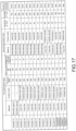
- Fig. 17 is a diagram showing the respective examples and the respective comparative examples according to the second embodiment.
- the material, commodity name, thickness, area occupation rate, and weight per unit area of the first deformation layer 44 in the respective examples and the respective comparative examples are shown.
- the material and commodity name of the second deformation layer 48 are shown.
- Fig. 17 the detection sensitivity of the pressure sensor 22' in the perpendicular direction when the load Fz of 10 gf, 1 kgf was applied to the pressure sensor 22 downward in the perpendicular direction is shown. It should be noted that the detection sensitivity of the pressure sensor 22' in the perpendicular direction shown in Fig. 17 is not the sensitivity of the entire sensor 20, and represents the detection sensitivity of the pressure sensor 22' alone.
- Example 13 a nanofiber was used as the material of the first deformation layer 44, the thickness of the first deformation layer 44 was 150 um, and the area occupation rate was 100%. Further, in Example 13, the weight per unit area was 4 mg/cm 2 . Further, in Example 13, Neofix (registered trademark) 100, which is a double-sided tape, was used as the material of the second deformation layer 48.
- Example 13 the detection sensitivity of the pressure sensor 22' in the perpendicular direction when the load Fz of 10 gf and 1 kgf was applied to the pressure sensor 22' in the perpendicular direction was 10 and 150, respectively. This detection sensitivity was a high value during a low-pressure time and during a high-pressure time.
- Example 14 a nanofiber was used as the material of the first deformation layer 44, the thickness of the first deformation layer 44 was 400 um, and the area occupation rate was 100%. Further, in Example 14, the weight per unit area was 10 mg/cm 2 . Further, in Example 14, Neofix (registered trademark) 100, which is a double-sided tape, was used as the material of the second deformation layer 48.
- Example 14 the detection sensitivity of the pressure sensor 22' in the perpendicular direction when the load Fz of 10 gf and 1 kgf was applied to the pressure sensor 22' in the perpendicular direction was 40 and 300, respectively. This detection sensitivity was a high value during a low-pressure time and during a high-pressure time.
- Example 15 In Example 15, PORON (registered trademark) SR-S-32P, which is a foam film, was used as the material of the first deformation layer 44, the thickness of the first deformation layer 44 was 200 um, and the area occupation rate was 100%. Further, in Example 15, the weight per unit area was 6 mg/cm 2 . Further, in Example 15, Neofix (registered trademark) 100, which is a double-sided tape, was used as the material of the second deformation layer 48.
- PORON registered trademark
- SR-S-32P which is a foam film
- Example 15 the detection sensitivity of the pressure sensor 22' in the perpendicular direction when the load Fz of 10 gf and 1 kgf was applied to the pressure sensor 22' in the perpendicular direction was 10 and 200, respectively. This detection sensitivity was a high value during a low-pressure time and during a high-pressure time.
- Example 16 PORON (registered trademark) SS-32P, which is a foam film, was used as the material of the first deformation layer 44, the thickness of the first deformation layer 44 was 500 um, and the area occupation rate was 100%. Further, in Example 16, the weight per unit area was 16 mg/cm 2 . Further, in Example 16, Neofix (registered trademark) 100, which is a double-sided tape, was used as the material of the second deformation layer 48.
- Example 16 the detection sensitivity of the pressure sensor 22' in the perpendicular direction when the load Fz of 10 gf and 1 kgf was applied to the pressure sensor 22' in the perpendicular direction was 30 and 350, respectively. This detection sensitivity was a high value during a low-pressure time and during a high-pressure time.
- Example 17 PORON (registered trademark) SS-24P, which is a foam film, was used as the material of the first deformation layer 44, the thickness of the first deformation layer 44 was 300 um, and the area occupation rate was 100%. Further, in Example 17, the weight per unit area was 7 mg/cm 2 . Further, in Example 17, Neofix (registered trademark) 100, which is a double-sided tape, was used as the material of the second deformation layer 48.
- Example 17 the detection sensitivity of the pressure sensor 22' in the perpendicular direction when the load Fz of 10 gf and 1 kgf was applied to the pressure sensor 22' in the perpendicular direction was 50 and 350, respectively. This detection sensitivity was a high value during a low-pressure time and during a high-pressure time.
- Example 18 PORON (registered trademark) SS-24P, which is a foam film, was used as the material of the first deformation layer 44, the thickness of the first deformation layer 44 was 500 um, and the area occupation rate was 100%. Further, in Example 18, the weight per unit area was 12 mg/cm 2 . Further, in Example 18, Neofix (registered trademark) 100, which is a double-sided tape, was used as the material of the second deformation layer 48.
- Example 18 the detection sensitivity of the pressure sensor 22' in the perpendicular direction when the load Fz of 10 gf and 1 kgf was applied to the pressure sensor 22' in the perpendicular direction was 40 and 400, respectively. This detection sensitivity was a high value during a low-pressure time and during a high-pressure time.
- Example 19 PORON (registered trademark) SS-15P, which is a foam film, was used as the material of the first deformation layer 44, the thickness of the first deformation layer 44 was 500 um, and the area occupation rate was 100%. Further, in Example 19, the weight per unit area was 8 mg/cm 2 . Further, in Example 19, Neofix (registered trademark) 100, which is a double-sided tape, was used as the material of the second deformation layer 48.
- Example 19 the detection sensitivity of the pressure sensor 22' in the perpendicular direction when the load Fz of 10 gf and 1 kgf was applied to the pressure sensor 22' in the perpendicular direction was 50 and 400, respectively. This detection sensitivity was a high value during a low-pressure time and during a high-pressure time.
- Example 20 PORON (registered trademark) SR-S-40P, which is a foam film, was used as the material of the first deformation layer 44, the thickness of the first deformation layer 44 was 1000 um, and the area occupation rate was 100%. Further, in Example 20, the weight per unit area was 40 mg/cm 2 . Further, in Example 20, Neofix (registered trademark) 100, which is a double-sided tape, was used as the material of the second deformation layer 48.
- Example 20 the detection sensitivity of the pressure sensor 22' in the perpendicular direction when the load Fz of 10 gf and 1 kgf was applied to the pressure sensor 22' in the perpendicular direction was 15 and 200, respectively. This detection sensitivity was a high value during a low-pressure time and during a high-pressure time.
- Example 21 PORON (registered trademark) HH48, which is a foam film, was used as the material of the first deformation layer 44, the thickness of the first deformation layer 44 was 1000 um, and the area occupation rate was 100%. Further, in Example 21, the weight per unit area was 50 mg/cm 2 . Further, in Example 21, Neofix (registered trademark) 100, which is a double-sided tape, was used as the material of the second deformation layer 48.
- Example 21 the detection sensitivity of the pressure sensor 22' in the perpendicular direction when the load Fz of 10 gf and 1 kgf was applied to the pressure sensor 22' in the perpendicular direction was 10 and 150, respectively. This detection sensitivity was a high value during a low-pressure time and during a high-pressure time.
- Example 22 PORON (registered trademark) SS-24P, which is a foam film, was used as the material of the first deformation layer 44, the thickness of the first deformation layer 44 was 500 um, and the area occupation rate was 100%. Further, in Example 22, the weight per unit area was 12 mg/cm 2 . Further, in Example 22, PORON (registered trademark) SS-24P, which is a foam film, was used as the material of the second deformation layer 48.
- Example 22 the detection sensitivity of the pressure sensor 22' in the perpendicular direction when the load Fz of 10 gf and 1 kgf was applied to the pressure sensor 22' in the perpendicular direction was 60 and 500, respectively. This detection sensitivity was a high value during a low-pressure time and during a high-pressure time.
- Example 23 PORON (registered trademark) SS-24P, which is a foam film, was used as the material of the first deformation layer 44, the thickness of the first deformation layer 44 was 500 um, and the area occupation rate was 100%. Further, in Example 23, the weight per unit area was 12 mg/cm 2 . Further, in Example 23, as the material of the second deformation layer 48, PORON (registered trademark) SS-32P, which is a foam film, was used.
- Example 23 the detection sensitivity of the pressure sensor 22' in the perpendicular direction when the load Fz of 10 gf and 1 kgf was applied to the pressure sensor 22' in the perpendicular direction was 50 and 600, respectively. This detection sensitivity was a high value during a low-pressure time and during a high-pressure time.
- Example 24 PORON (registered trademark) SS-24P, which is a foam film, was used as the material of the first deformation layer 44, the thickness of the first deformation layer 44 was 500 um, and the area occupation rate was 100%. Further, in Example 24, the weight per unit area was 12 mg/cm 2 . Further, in Example 24, as the material of the second deformation layer 48, silicone gel, FFG-42100-1t was used.
- Example 24 the detection sensitivity of the pressure sensor 22' in the perpendicular direction when the load Fz of 10 gf and 1 kgf was applied to the pressure sensor 22' in the perpendicular direction was 40 and 400, respectively. This detection sensitivity was a high value during a low-pressure time and during a high-pressure time.
- Comparative Example 6 Purecell (registered trademark) S010, which is a foam film, was used as the material of the first deformation layer 44, the thickness of the first deformation layer 44 was 100 um, and the area occupation rate was 100%. Further, in Comparative Example 6, the weight per unit area was 3 mg/cm 2 . Further, in Comparative Example 6, Neofix (registered trademark) 100, which is a double-sided tape, was used as the material of the second deformation layer 48.
- the detection sensitivity of the pressure sensor 22 in the perpendicular direction when the load Fz of 10 gf and 1 kgf was applied to the pressure sensor 22 in the perpendicular direction was 5 and 100, respectively. This detection sensitivity was a low value during a low-pressure time and during a high-pressure time.
- Comparative Example 6 since the thickness of the first deformation layer 44 is 100 ⁇ m, which is too small, the deformation amount during a low-pressure time and during a high-pressure time is small and the detection sensitivity is bad.
- Comparative Example 7 PORON (registered trademark) H48, which is a foam film, was used as the material of the first deformation layer 44, the thickness of the first deformation layer 44 was 1500 um, and the area occupation rate was 100%. Further, in Comparative Example 7, the weight per unit area was 70 mg/cm 2 . Further, in Comparative Example 7, Neofix (registered trademark) 100, which is a double-sided tape, was used as the material of the second deformation layer 48.
- the detection sensitivity of the pressure sensor 22 in the perpendicular direction when the load Fz of 10 gf and 1 kgf was applied to the pressure sensor 22 in the perpendicular direction was 5 and 30, respectively. This detection sensitivity was a low value during a low-pressure time and during a high-pressure time.
- Comparative Example 7 since the weight per unit area of the first deformation layer 44 is 70, which is too large, the first deformation layer 44 is hard, the deformation amount during a low-pressure time and during a high-pressure time is small, and the detection sensitivity is bad. Further, in Comparative Example 7, since the thickness of the first deformation layer 44 is 1500 ⁇ m, which is too large, with the deformation amount during a low-pressure time, the distance between the sensor electrode layer 47 and the first reference electrode layer 42 and the second reference electrode layer 50 is too long, and the detection sensitivity is bad.
- the detection sensitivity of the pressure sensor 22 in the perpendicular direction when the load Fz of 10 gf and 1 kgf was applied to the pressure sensor 22 in the perpendicular direction was 5 and 50, respectively. This detection sensitivity was a low value during a low-pressure time and during a high-pressure time.
- Comparative Example 8 since the weight per unit area of the first deformation layer 44 is 70, which is too large, the first deformation layer 44 is hard, the deformation amount during a low-pressure time and during a high-pressure time is small, and the detection sensitivity is bad. Further, in Comparative Example 8, since the thickness of the first deformation layer 44 is 1500 ⁇ m, which is too large, and with the deformation amount during a low-pressure time, the distance between the sensor electrode layer 47 and the first reference electrode layer 42 and the second reference electrode layer 50 is too long, and the detection sensitivity is bad.
- the detection sensitivity to the load Fz in the perpendicular direction can be improved.
- the pressure sensor 22' according to the third embodiment has a laminate structure in which the second electrode film layer 51 (second reference electrode layer 50), the second deformation layer 48, the sensor electrode layer 47, the first deformation layer 44, the first electrode film layer 43 (first reference electrode layer 42) are stacked in order from the side of the lower layer in the perpendicular direction.
- the thickness of the first deformation layer 44 is 100 um or less and the weight per unit area of the first deformation layer 44 is 3 mg/cm 2 or less. Further, in the third embodiment, the thickness of the second deformation layer 48 is more than 100 um and 1000 um or less and the weight per unit area of the second deformation layer 48 is 50 mg/cm 2 or more.
- the detection sensitivity during a low-pressure time is improved by the first deformation layer 44 while the detection sensitivity during a low-pressure time and during a high-pressure time is improved by the second deformation layer 48.
- Fig. 18 is a diagram showing the respective examples and the respective comparative examples according to the third embodiment.
- the thickness, weight per unit area, commodity name, and material of the first deformation layer 44 in the respective examples and the respective comparative examples are shown.
- the thickness, weight per unit area, commodity name, and material of the second deformation layer 48 are shown.
- Fig. 18 to the sensor 20 downward in the perpendicular direction 10 kPa, the detection sensitivity of the sensor 20 when the load Fz of 100 kPa was applied in the perpendicular direction is shown. Further, in Fig. 18 , the displacement detection sensitivity when the displacement was 5 um is shown.
- Example 25 the thickness of the first deformation layer 44 was 100pm, and the weight per unit area was 2.5 mg/cm 2 . Further, in Example 25, a nanofiber including polyurethane was used as the material of the first deformation layer 44.
- Example 25 the thickness of the second deformation layer 48 was 500 um, and the weight per unit area was 12 mg/cm 2 . Further, in Example 25, as the material of the second deformation layer 48, PORON (registered trademark) SS-24DP, which is a foam film including polyurethane, was used.
- Example 25 the detection sensitivity of the sensor 20 in the perpendicular direction when the load Fz of 1 kPa and 100 kPa was applied to the sensor 20 in the perpendicular direction was 3 and 120, respectively. This detection sensitivity was a high value during a low-pressure time and during a high-pressure time. Further, in Example 25, the displacement detection sensitivity when the displacement was 5 um was 5, a high value.
- Example 26 the thickness of the first deformation layer 44 was 25um, and the weight per unit area was 0.9 mg/cm 2 . Further, in Example 26, a nanofiber including polyurethane was used as the material of the first deformation layer 44.
- Example 26 the thickness of the second deformation layer 48 was 500 um, and the weight per unit area was 12 mg/cm 2 . Further, in Example 26, as the material of the second deformation layer 48, PORON (registered trademark) SS-24DP, which is a foam film including polyurethane, was used.
- Example 26 the detection sensitivity of the sensor 20 in the perpendicular direction when the load Fz of 1 kPa and 100 kPa was applied to the sensor 20 in the perpendicular direction was 3 and 120, respectively. This detection sensitivity was a high value during a low-pressure time and during a high-pressure time. Further, in Example 26, the displacement detection sensitivity when the displacement was 5 um was 10, a high value.
- Example 27 the thickness of the first deformation layer 44 was 25um, and the weight per unit area was 0.9 mg/cm 2 . Further, in Example 27, a nanofiber including polyurethane was used as the material of the first deformation layer 44.
- Example 27 the thickness of the second deformation layer 48 was 500 um, was the weight per unit area was 7.5 mg/cm 2 . Further, in Example 27, as the material of the second deformation layer 48, PORON (registered trademark) SS-15DP, which is a foam film including polyurethane, was used.
- Example 27 the detection sensitivity of the sensor 20 in the perpendicular direction when the load Fz of 1 kPa and 100 kPa was applied to the sensor 20 in the perpendicular direction was 10 and 200, respectively. This detection sensitivity was a high value during a low-pressure time and during a high-pressure time. Further, in Example 27, the displacement detection sensitivity when the displacement was 5 um was 15, a high value.
- the thickness of the first deformation layer 44 was 500pm, and the weight per unit area was 12 mg/cm 2 . Further, in Comparative Example 9, PORON (registered trademark) SS-24DP, which is a foam film including polyurethane, was used as the material of the first deformation layer 44.
- the thickness of the second deformation layer 48 was 100 ⁇ m, and as the material of the second deformation layer 48, Neofix (registered trademark) 100, which is a double-sided tape, was used.
- the detection sensitivity of the sensor 20 in the perpendicular direction when the load Fz of 1 kPa and 100 kPa was applied to the sensor 20 in the perpendicular direction was 3 and 120, respectively. This detection sensitivity was a high value during a low-pressure time and during a high-pressure time. On the other hand, in Comparative Example 9, the displacement detection sensitivity when the displacement was 5 um was 1 or less, a low value.
- the thickness of the first deformation layer 44 was 25um, and the weight per unit area was 0.9 mg/cm 2 . Further, in Comparative Example 10, a nanofiber including polyurethane was used as the material of the first deformation layer 44.
- the thickness of the second deformation layer 48 was 100 ⁇ m, and as the material of the second deformation layer 48, Neofix (registered trademark) 100, which is a double-sided tape, was used.
- the detection sensitivity of the sensor 20 in the perpendicular direction when the load Fz of 1 kPa and 100 kPa was applied to the sensor 20 in the perpendicular direction was 2 and 20, respectively. This detection sensitivity was not problematic during a low-pressure time while the detection sensitivity was a low value during a high-pressure time. Further, in Comparative Example 10, the displacement detection sensitivity when the displacement was 20 um was 20, a high value.
- the robot hand 10 has been described as an example of an electronic apparatus on which the sensor 20 is mounted.
- the electronic apparatus on which the sensor 20 is mounted is not limited to the robot hand 10, and may be another apparatus such as a mobile phone (including a smartphone) and a PC.
- any apparatus can be considered as the electronic apparatus as long as it is an apparatus on which the sensor 20 is mounted.
- the present technology can also take the following configurations.
Landscapes
- Chemical & Material Sciences (AREA)
- Analytical Chemistry (AREA)
- Physics & Mathematics (AREA)
- General Physics & Mathematics (AREA)
- Engineering & Computer Science (AREA)
- Power Engineering (AREA)
- Force Measurement Appropriate To Specific Purposes (AREA)
Applications Claiming Priority (2)
| Application Number | Priority Date | Filing Date | Title |
|---|---|---|---|
| JP2020065244 | 2020-03-31 | ||
| PCT/JP2021/009800 WO2021200014A1 (ja) | 2020-03-31 | 2021-03-11 | センサ及び電子機器 |
Publications (2)
| Publication Number | Publication Date |
|---|---|
| EP4130698A1 true EP4130698A1 (de) | 2023-02-08 |
| EP4130698A4 EP4130698A4 (de) | 2023-10-11 |
Family
ID=77928636
Family Applications (1)
| Application Number | Title | Priority Date | Filing Date |
|---|---|---|---|
| EP21779355.3A Withdrawn EP4130698A4 (de) | 2020-03-31 | 2021-03-11 | Sensor und elektronische vorrichtung |
Country Status (4)
| Country | Link |
|---|---|
| US (1) | US12345591B2 (de) |
| EP (1) | EP4130698A4 (de) |
| JP (1) | JP7597109B2 (de) |
| WO (1) | WO2021200014A1 (de) |
Families Citing this family (2)
| Publication number | Priority date | Publication date | Assignee | Title |
|---|---|---|---|---|
| CN116323120A (zh) * | 2020-11-17 | 2023-06-23 | 索尼集团公司 | 传感器装置和机器人装置 |
| JP7558054B2 (ja) * | 2020-12-24 | 2024-09-30 | 横河電機株式会社 | 力検出器及び力検出システム |
Family Cites Families (17)
| Publication number | Priority date | Publication date | Assignee | Title |
|---|---|---|---|---|
| CH609774A5 (de) * | 1977-01-21 | 1979-03-15 | Semperit Ag | |
| US6809529B2 (en) * | 2001-08-10 | 2004-10-26 | Wacoh Corporation | Force detector |
| JP5101078B2 (ja) * | 2006-10-19 | 2012-12-19 | 旭化成ホームズ株式会社 | 柱状体の制振構造 |
| JP5003336B2 (ja) * | 2007-07-31 | 2012-08-15 | ソニー株式会社 | 検出装置、ロボット装置、および入力装置 |
| EP2071312B1 (de) * | 2007-12-13 | 2015-09-16 | Yamaha Corporation | Drucksensor und Dateneingabevorrichtung |
| US9524020B2 (en) * | 2010-10-12 | 2016-12-20 | New York University | Sensor having a mesh layer with protrusions, and method |
| US9158369B2 (en) * | 2010-10-12 | 2015-10-13 | Tactonic Technologies, Llc | Sensors having a connecting frame and method for composite sensors |
| JP2012247297A (ja) * | 2011-05-27 | 2012-12-13 | Tokai Rubber Ind Ltd | 触覚センサ |
| GB201219632D0 (en) * | 2012-10-31 | 2012-12-12 | Univ Southampton | Apparatus for sensing and measuring pressure and shear components of a force at an interface between two surfaces |
| US9848775B2 (en) * | 2013-05-22 | 2017-12-26 | The Board Of Trustees Of The Leland Stanford Junior University | Passive and wireless pressure sensor |
| US20170177114A1 (en) * | 2014-08-07 | 2017-06-22 | 3M Innovative Properties Company | Force-sensing capacitor elements, deformable membranes and electronic devices fabricated therefrom |
| JP6643647B2 (ja) | 2015-03-19 | 2020-02-12 | パナソニックIpマネジメント株式会社 | 感圧素子 |
| KR102553036B1 (ko) * | 2016-06-29 | 2023-07-07 | 엘지이노텍 주식회사 | 압력 감지 센서 |
| JP6904358B2 (ja) * | 2016-08-15 | 2021-07-14 | ソニーグループ株式会社 | センサ、入力装置および電子機器 |
| WO2019135401A1 (ja) * | 2018-01-05 | 2019-07-11 | ソニー株式会社 | センサ、入力装置および電子機器 |
| US11946821B2 (en) * | 2018-07-10 | 2024-04-02 | The Board Of Trustees Of The Leland Stanford Junior University | Capacitive and tactile sensors and related sensing methods |
| JP6757530B2 (ja) * | 2018-09-20 | 2020-09-23 | Nissha株式会社 | 圧力センサーシート |
-
2021
- 2021-03-11 US US17/908,051 patent/US12345591B2/en active Active
- 2021-03-11 EP EP21779355.3A patent/EP4130698A4/de not_active Withdrawn
- 2021-03-11 JP JP2022511757A patent/JP7597109B2/ja active Active
- 2021-03-11 WO PCT/JP2021/009800 patent/WO2021200014A1/ja not_active Ceased
Also Published As
| Publication number | Publication date |
|---|---|
| US20230009475A1 (en) | 2023-01-12 |
| JPWO2021200014A1 (de) | 2021-10-07 |
| WO2021200014A1 (ja) | 2021-10-07 |
| EP4130698A4 (de) | 2023-10-11 |
| JP7597109B2 (ja) | 2024-12-10 |
| US12345591B2 (en) | 2025-07-01 |
Similar Documents
| Publication | Publication Date | Title |
|---|---|---|
| US20220171502A1 (en) | Flexible capacitive tactile sensor and method for manufacturing same and tactile sensing system | |
| EP4130698A1 (de) | Sensor und elektronische vorrichtung | |
| CN101065674B (zh) | 用于检测坠落的系统和方法 | |
| US8446360B2 (en) | Force sensor for use in an input device and methods for constructing and using the sensor | |
| KR101597861B1 (ko) | 센서, 센서를 포함하는 디스플레이, 및 센서를 사용하는 방법 | |
| Chun et al. | A highly sensitive force sensor with fast response based on interlocked arrays of indium tin oxide nanosprings toward human tactile perception | |
| US10078027B2 (en) | Pressure sensing element including electrode having protrusion | |
| US20160378255A1 (en) | Self-Calibration of Force Sensors and Inertial Compensation | |
| EP3037797A1 (de) | Druckmesselement mit elektrode mit protrusion mit elastischen eigenschaften | |
| US20080011080A1 (en) | Microelectromechanical inertial sensor, in particular for free-fall detection applications | |
| TWI464406B (zh) | 三軸式加速度感測器 | |
| US20130167641A1 (en) | Mems acceleration sensor | |
| KR20100019808A (ko) | 누름힘의 세기 및 작용위치 검출용 터치입력구조, 이를 이용한 터치입력장치 및 누름힘의 세기 및 작용위치 검출방법 | |
| US20220144624A1 (en) | Electrode layer partitioning | |
| US6840106B1 (en) | Sensor using an actuator for self-test and method therefor | |
| EP4249878A1 (de) | Sensorvorrichtung und robotervorrichtung | |
| US20240269829A1 (en) | Robot apparatus, sensor apparatus, and control device | |
| CN112798156A (zh) | 一种纳米线压力传感器及传感器阵列 | |
| EP4491355A1 (de) | Robotervorrichtung und sensorvorrichtung | |
| EP4563959A1 (de) | Eingabevorrichtung mit filmartigem kraftsensor und lastdetektionsverfahren dafür | |
| CN112798163B (zh) | 一种纳米线压力传感器制备方法 | |
| JP2011174881A (ja) | 静電容量型加速度センサ | |
| CN114052717B (zh) | 一种生物步态特征识别装置 | |
| JP2009008414A (ja) | 落下検知センサ | |
| DE102019101585A1 (de) | Bedienanordnung mit verbesserter Betätigungskraft getriggerter Vornahme einer Schalt- und Steuerfunktion |
Legal Events
| Date | Code | Title | Description |
|---|---|---|---|
| STAA | Information on the status of an ep patent application or granted ep patent |
Free format text: STATUS: THE INTERNATIONAL PUBLICATION HAS BEEN MADE |
|
| PUAI | Public reference made under article 153(3) epc to a published international application that has entered the european phase |
Free format text: ORIGINAL CODE: 0009012 |
|
| STAA | Information on the status of an ep patent application or granted ep patent |
Free format text: STATUS: REQUEST FOR EXAMINATION WAS MADE |
|
| 17P | Request for examination filed |
Effective date: 20220914 |
|
| AK | Designated contracting states |
Kind code of ref document: A1 Designated state(s): AL AT BE BG CH CY CZ DE DK EE ES FI FR GB GR HR HU IE IS IT LI LT LU LV MC MK MT NL NO PL PT RO RS SE SI SK SM TR |
|
| DAV | Request for validation of the european patent (deleted) | ||
| DAX | Request for extension of the european patent (deleted) | ||
| A4 | Supplementary search report drawn up and despatched |
Effective date: 20230908 |
|
| RIC1 | Information provided on ipc code assigned before grant |
Ipc: G01L 5/00 20060101ALI20230904BHEP Ipc: G01L 5/165 20200101AFI20230904BHEP |
|
| STAA | Information on the status of an ep patent application or granted ep patent |
Free format text: STATUS: THE APPLICATION HAS BEEN WITHDRAWN |
|
| 18W | Application withdrawn |
Effective date: 20250424 |