EP4130948B1 - Dispositif électronique, et procédé de commande et module de commande associés - Google Patents
Dispositif électronique, et procédé de commande et module de commande associés Download PDFInfo
- Publication number
- EP4130948B1 EP4130948B1 EP21774272.5A EP21774272A EP4130948B1 EP 4130948 B1 EP4130948 B1 EP 4130948B1 EP 21774272 A EP21774272 A EP 21774272A EP 4130948 B1 EP4130948 B1 EP 4130948B1
- Authority
- EP
- European Patent Office
- Prior art keywords
- region
- display screen
- charged region
- conductive part
- fingerprint module
- Prior art date
- Legal status (The legal status is an assumption and is not a legal conclusion. Google has not performed a legal analysis and makes no representation as to the accuracy of the status listed.)
- Active
Links
Images

Classifications
-
- G—PHYSICS
- G06—COMPUTING OR CALCULATING; COUNTING
- G06F—ELECTRIC DIGITAL DATA PROCESSING
- G06F3/00—Input arrangements for transferring data to be processed into a form capable of being handled by the computer; Output arrangements for transferring data from processing unit to output unit, e.g. interface arrangements
- G06F3/01—Input arrangements or combined input and output arrangements for interaction between user and computer
- G06F3/03—Arrangements for converting the position or the displacement of a member into a coded form
- G06F3/041—Digitisers, e.g. for touch screens or touch pads, characterised by the transducing means
- G06F3/0416—Control or interface arrangements specially adapted for digitisers
-
- G—PHYSICS
- G06—COMPUTING OR CALCULATING; COUNTING
- G06V—IMAGE OR VIDEO RECOGNITION OR UNDERSTANDING
- G06V40/00—Recognition of biometric, human-related or animal-related patterns in image or video data
- G06V40/10—Human or animal bodies, e.g. vehicle occupants or pedestrians; Body parts, e.g. hands
- G06V40/12—Fingerprints or palmprints
- G06V40/13—Sensors therefor
-
- G—PHYSICS
- G06—COMPUTING OR CALCULATING; COUNTING
- G06F—ELECTRIC DIGITAL DATA PROCESSING
- G06F21/00—Security arrangements for protecting computers, components thereof, programs or data against unauthorised activity
- G06F21/30—Authentication, i.e. establishing the identity or authorisation of security principals
- G06F21/31—User authentication
- G06F21/32—User authentication using biometric data, e.g. fingerprints, iris scans or voiceprints
-
- G—PHYSICS
- G06—COMPUTING OR CALCULATING; COUNTING
- G06F—ELECTRIC DIGITAL DATA PROCESSING
- G06F3/00—Input arrangements for transferring data to be processed into a form capable of being handled by the computer; Output arrangements for transferring data from processing unit to output unit, e.g. interface arrangements
- G06F3/01—Input arrangements or combined input and output arrangements for interaction between user and computer
- G06F3/03—Arrangements for converting the position or the displacement of a member into a coded form
- G06F3/041—Digitisers, e.g. for touch screens or touch pads, characterised by the transducing means
- G06F3/0416—Control or interface arrangements specially adapted for digitisers
- G06F3/04166—Details of scanning methods, e.g. sampling time, grouping of sub areas or time sharing with display driving
-
- G—PHYSICS
- G06—COMPUTING OR CALCULATING; COUNTING
- G06F—ELECTRIC DIGITAL DATA PROCESSING
- G06F3/00—Input arrangements for transferring data to be processed into a form capable of being handled by the computer; Output arrangements for transferring data from processing unit to output unit, e.g. interface arrangements
- G06F3/01—Input arrangements or combined input and output arrangements for interaction between user and computer
- G06F3/03—Arrangements for converting the position or the displacement of a member into a coded form
- G06F3/041—Digitisers, e.g. for touch screens or touch pads, characterised by the transducing means
- G06F3/044—Digitisers, e.g. for touch screens or touch pads, characterised by the transducing means by capacitive means
-
- G—PHYSICS
- G06—COMPUTING OR CALCULATING; COUNTING
- G06V—IMAGE OR VIDEO RECOGNITION OR UNDERSTANDING
- G06V40/00—Recognition of biometric, human-related or animal-related patterns in image or video data
- G06V40/10—Human or animal bodies, e.g. vehicle occupants or pedestrians; Body parts, e.g. hands
- G06V40/12—Fingerprints or palmprints
- G06V40/13—Sensors therefor
- G06V40/1306—Sensors therefor non-optical, e.g. ultrasonic or capacitive sensing
-
- G—PHYSICS
- G06—COMPUTING OR CALCULATING; COUNTING
- G06V—IMAGE OR VIDEO RECOGNITION OR UNDERSTANDING
- G06V40/00—Recognition of biometric, human-related or animal-related patterns in image or video data
- G06V40/10—Human or animal bodies, e.g. vehicle occupants or pedestrians; Body parts, e.g. hands
- G06V40/12—Fingerprints or palmprints
- G06V40/13—Sensors therefor
- G06V40/1324—Sensors therefor by using geometrical optics, e.g. using prisms
Definitions
- the present invention relates to the field of communications technologies, and in particular, to an electronic device, a control method and a control module of the same, and a computer-readable storage medium.
- an electronic device With the rapid development of electronic devices, an electronic device is used more and more widely, and electronic devices such as a mobile phone, a tablet computer, and the like play an increasingly important role in people's work, life, entertainment, and other aspects.
- electronic devices such as a mobile phone, a tablet computer, and the like play an increasingly important role in people's work, life, entertainment, and other aspects.
- a screen-to-body ratio of an electronic device is increasing.
- a fingerprint module for unlocking or payment may be disposed in or under a screen of the electronic device; and a fingerprint recognition function may be implemented through an optical fingerprint recognition module or an ultrasonic module. Therefore, an impact of the fingerprint module on the screen-to-body ratio of the electronic device can be avoided.
- the fingerprint module can only be fixed at a certain position in or under the screen of the electronic device.
- a user needs to accurately touch the position of the fingerprint module, which seriously affects user's experience.
- CN109375714A discloses a terminal for full-screen identification fingerprint and a method for full-screen identification fingerprint of the terminal.
- the terminal comprises a touch screen, a movement module and an optical fingerprint module positioned below the touch screen, wherein the touch screen is used for detecting a touch operation and calculating a touch position when the touch operation is detected;
- the moving module is used for moving the optical fingerprint module directly below the touch position;
- the optical fingerprint module is configured to identify a fingerprint at the touch position.
- the invention firstly calculates the touch position of the finger on the terminal touch screen, and then moves the optical fingerprint module to the touch position, so that the terminal user can realize fingerprint identification at any position on the terminal touch screen, instead of being limited to a fixed position on the terminal touch screen, thereby improving the user's sense of use.
- CN109241957A discloses an electronic device, a fingerprint acquisition method, a device, a mobile terminal and a storage medium.
- the electronic device comprises a display screen; a position sensor for acquiring a touch position of a user's finger on the display screen; a fingerprint sensor movable relative to the display screen, the fingerprint sensor movable to a touch position on the display screen to collect a user's fingerprint.
- a location sensor is arranged to detect a touch position of a user's fin on that display screen, the movable fingerprint sensor moves to the touch position to collect the fingerprint information of the user's finger, without the user knowing the input fingerprint position, and without the user changing the touch position when the user touches the wrong position, the fingerprint sensor automatically adjusts the position to collect the user's fingerprint.
- the operation of user input fingerprint is simplified and the efficiency of fingerprint collection is improved.
- the present invention discloses an electronic device, as well as a control method and a control module of the same, to resolve a problem that a fingerprint module in an existing electronic device is inconvenient to use.
- an embodiment of the present invention provides an electronic device.
- the electronic device includes:
- an embodiment of the present invention provides a control method of an electronic device.
- the control method includes:
- an embodiment of the present invention provides an electronic device.
- the electronic device includes a processor, a memory, and a computer program stored in the memory and executable on the processor, where when the computer program is executed by the processor, the actions of the foregoing control method are implemented.
- a drive mechanism can drive a fingerprint module to move in an inner cavity, so that the fingerprint module can move to a position corresponding to any region of a display screen.
- An existing electronic device can be unlocked only by touching a specified region of the electronic device by user's finger.
- the fingerprint module can move to a region corresponding to user's finger, so that user's finger can touch any position of the display screen to unlock the electronic device, thereby increasing unlock efficiency. Therefore, a user can unlock the electronic device conveniently, thereby having better use experience.
- the electronic device further includes a rubber frame 750.
- the rubber frame 750 is disposed in the inner cavity 300.
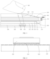
- the reflection part 740 is connected to the rubber frame 750 via optical clear adhesive 800. Based on this, compared with the existing electronic device, the electronic device in this embodiment of the present invention does not need an iron frame, which facilitates thinning design of the electronic device.
- the electronic device further includes a light-emitting component 900.
- the light-emitting component 900 may be disposed in the shell 100.
- the fingerprint module 400 is an optical fingerprint module.
- the light-emitting component 900 emits light to the first region of the display screen 200, so that the light-emitting component 900 emits the light to user's finger 500.
- the light shone on user's finger 500 is reflected to shine on the fingerprint module 400.
- a first arrow 910 in FIG. 1 is an emergent direction of the light; and a second arrow 920 in FIG.
- the 3M material is a reflection material formed by compounding a reflection layer of glass beads with a polymer material such as PVC (Polyvinyl chloride) and PU (Polyurethane).
- PVC Polyvinyl chloride
- PU Polyurethane
- action 200 specifically includes the following actions:
- the user when using the fingerprint unlocking function of the electronic device, the user first triggers a fingerprint recognition function of the electronic device by touching any position of the display screen 200.
- a mainboard of the electronic device senses position information of the user's finger 500 based on a change of a capacitance of the display screen 200, thereby receiving the tactile signal generated when user's finger 500 touches the display screen 200.
- position recognition is perform on the position of user's finger 500 in response to the tactile signal, to obtain the position corresponding to the first region.
- the first charged region is controlled to be disposed opposite the second charged region, and the polarity of the first charge carried in the first charged region is controlled to be the same as that of the second charge carried in the second charged region, so that the fingerprint module 400 can be suspended in the inner cavity 300. Therefore, movement of the fingerprint module 400 can be implemented conveniently.
- Action 320 Control a polarity of at least part of a third charge carried in the third charged region to be opposite to that of the first charge carried in the first charged region, thereby driving the fingerprint module 400 to move to a position corresponding to the third charged region, where the third charged region is disposed opposite the first region.
- an embodiment of the present invention further provides a control module.
- the control module includes:
- the controlling module includes a first control unit and a second control unit.
- the first control unit is configured to control the first charged region to be disposed opposite the second charged region, and a polarity of a first charge carried in the first charged region to be the same as that of a second charge carried in the second charged region.
- the second control unit is configured to control a polarity of at least part of a third charge carried in the third charged region to be opposite to that of the first charge carried in the first charged region, thereby driving the fingerprint module 400 to move to the position corresponding to the first region.
- An embodiment of the present invention further discloses an electronic device, including a processor, a memory, and a computer program stored in the memory and executable on the processor.
- the computer program is executed by the processor, the actions of the control method in any one of the foregoing embodiments are implemented.
- An embodiment of the present invention further discloses a computer-readable storage medium.
- the computer-readable storage medium stores a computer program, where when the computer program is executed by a processor, the actions of the control method in any one of the foregoing embodiments are implemented.
- the electronic device disclosed in this embodiment of the present invention may be a smart phone, a tablet computer, an ebook reader, a wearable device (for example, a smart watch), a video game console, and the like.
- a specific type of the electronic device is not limited in this embodiment of the present invention.
Landscapes
- Engineering & Computer Science (AREA)
- Theoretical Computer Science (AREA)
- Physics & Mathematics (AREA)
- General Engineering & Computer Science (AREA)
- General Physics & Mathematics (AREA)
- Human Computer Interaction (AREA)
- Multimedia (AREA)
- Computer Security & Cryptography (AREA)
- Optics & Photonics (AREA)
- Computer Hardware Design (AREA)
- Software Systems (AREA)
- Image Input (AREA)
- Telephone Function (AREA)
- User Interface Of Digital Computer (AREA)
Claims (10)
- Module de commande d'un dispositif électronique mettant en œuvre le procédé selon l'une quelconque des revendications 7 à 9, dans lequel le dispositif électronique comprend :une coque (100) ;un écran d'affichage (200), dans lequel l'écran d'affichage (200) est disposé dans la coque (100), et une cavité interne (300) est formée entre la coque (100) et l'écran d'affichage (200);un module d'empreintes digitales (400), dans lequel le module d'empreintes digitales (400) est disposé de manière mobile dans la cavité interne (300) ; etun mécanisme d'entraînement, dans lequel le mécanisme d'entraînement est connecté au module d'empreintes digitales (400) et dans un cas où l'écran d'affichage (200) est touché, entraîne le module d'empreintes digitales (400) à se déplacer vers une position correspondant à une première zone, et la première zone est une zone de l'écran d'affichage (200) et qui est touchée ;dans lequel le module de commande est caractérisé en ce que, le module de commande comprend :un module de réception, configuré pour recevoir une entrée du doigt de l'utilisateur (500) sur l'écran d'affichage (200) ;un module d'obtention, configuré pour obtenir une position de l'entrée sur l'écran d'affichage (200) en réponse à l'entrée ; etun module de commande, configuré pour commander le mécanisme d'entraînement pour entraîner le module d'empreintes digitales (400) à se déplacer vers une position correspondant à une première zone, dans laquelle la position de l'entrée sur l'écran d'affichage (200) est la position qui correspond à la première zone ;dans lequel le mécanisme d'entraînement comprend une première partie conductrice (610) et une seconde partie conductrice (620), où la première partie conductrice (610) est disposée dans le module d'empreintes digitales (400), la seconde partie conductrice (620) est disposée dans la cavité interne (300), la première partie conductrice (610) est disposée à l'opposé de la seconde partie conductrice (620), la première partie conductrice (610) comprend une première zone chargée, la seconde partie conductrice (620) comprend une seconde zone chargée et une troisième zone chargée, et le module de commande comprend en outre :une première unité de commande, configurée pour commander la première zone chargée à être disposée à l'opposé de la seconde zone chargée, et une polarité d'une première charge transportée dans la première zone chargée pour être la même que celle d'une seconde charge transportée dans la seconde zone chargée ; etune deuxième unité de commande, configurée pour commander une polarité d'au moins une partie d'une troisième charge transportée dans la troisième zone chargée à être opposée à celle de la première charge transportée dans la première zone chargée, ainsi entraînant le module d'empreintes digitales (400) à se déplacer vers une position qui correspond à la troisième zone chargée, où la troisième zone chargée est disposée à l'opposé de la première zone.
- Module de commande selon la revendication 1, comprenant en outre :une unité de réception, configurée pour recevoir un signal tactile généré au moment où le doigt de l'utilisateur (500) touche l'écran d'affichage (200) ; etune unité de reconnaissance, configurée pour effectuer une reconnaissance de position de la position du doigt de l'utilisateur (500) en réponse au signal tactile afin d'obtenir la position qui correspond à la première zone.
- Module de commande selon la revendication 1, dans lequel la coque (100) comprend un cadre intermédiaire (110), l'écran d'affichage (200) est connecté au cadre intermédiaire (110), la cavité interne (300) est formée entre l'écran d'affichage (200) et le cadre intermédiaire (110), la première partie conductrice (610) est disposée sur une surface du module d'empreintes digitales (400) éloignée de l'écran d'affichage (200), et la seconde partie conductrice (620) est disposée sur une surface du cadre intermédiaire (110) faisant face au module d'empreintes digitales (400).
- Module de commande selon la revendication 3, dans lequel le dispositif électronique comprend en outre un module de rétroéclairage, où le module de rétroéclairage est monté sur un côté de l'écran d'affichage (200) faisant face à la cavité interne (300), et comprend une partie d'amélioration de la lumière (710), une partie de diffusion (720), une partie de guidage de la lumière (730) et une partie de réflexion (740) qui sont disposées séquentiellement en direction de la cavité interne (300).
- Module de commande selon la revendication 4, dans lequel le dispositif électronique comprend en outre un cadre en caoutchouc (750), où le cadre en caoutchouc (750) est disposé dans la cavité interne (300), et la partie de réflexion (740) est connectée au cadre en caoutchouc (750) par un adhésif optique transparent (800).
- Module de commande selon la revendication 1, dans lequel le dispositif électronique comprend en outre un composant électroluminescent (900), où le composant électroluminescent (900) est disposé dans la coque (100), le module d'empreinte digitale (400) est un module d'empreinte digitale optique, et dans un cas où l'écran d'affichage (200) est touché, le composant électroluminescent (900) émet de la lumière vers la première zone.
- Procédé de commande d'un dispositif électronique qui est mis en œuvre par le dispositif électronique selon l'une quelconque des revendications 1 à 6, caractérisé en ce que le procédé de commande comprend :recevoir une entrée du doigt de l'utilisateur (500) sur l'écran d'affichage (200) ;obtenir une position de l'entrée sur l'écran d'affichage (200) en réponse à l'entrée ; etcommander le mécanisme d'entraînement à entraîner le module d'empreintes digitales (400) pour se déplacer vers une position qui correspond à la première zone, où la position de l'entrée sur l'écran d'affichage (200) est la position qui correspond à la première zone.
- Procédé selon la revendication 7, dans lequel l'obtention d'une position de l'entrée sur l'écran d'affichage (200) en réponse à l'entrée comprend spécifiquement :recevoir un signal tactile qui est généré au moment où le doigt de l'utilisateur (500) touche l'écran d'affichage (200) ; eteffectuer une reconnaissance de position sur la position du doigt de l'utilisateur (500) en réponse au signal tactile pour obtenir la position qui correspond à la première zone.
- Procédé selon la revendication 7, dans lequel le mécanisme d'entraînement comprend une première partie conductrice (610) et une seconde partie conductrice (620), où la première partie conductrice (610) est disposée dans le module d'empreintes digitales (400), la seconde partie conductrice (620) est disposée dans la cavité interne (300), la première partie conductrice (610) est disposée à l'opposé de la seconde partie conductrice (620), la première partie conductrice (610) comprend une première zone chargée, et la seconde partie conductrice (620) comprend une seconde zone chargée et une troisième zone chargée ;
la commande du mécanisme d'entraînement pour entraîner le module d'empreintes digitales (400) à se déplacer vers une position correspondant à la première zone comprend spécifiquement:commander que la première zone chargée est disposée à l'opposé de la seconde zone chargée, et que la polarité d'une première charge transportée dans la première zone chargée est la même que celle d'une seconde charge transportée dans la seconde zone chargée ; etcontrôler qu'une polarité d'au moins une partie d'une troisième charge transportée dans la troisième zone chargée est opposée à celle de la première charge transportée dans la première zone chargée, ainsi entraînant le module d'empreintes digitales (400) à se déplacer vers une position qui correspond à la troisième zone chargée, où la troisième zone chargée est disposée à l'opposé de la première zone. - Support de stockage lisible par ordinateur qui stocke un programme informatique, caractérisé en ce que le programme informatique exécuté par un processeur effectue les actions du procédé de commande selon l'une quelconque des revendications 7 à 9.
Applications Claiming Priority (2)
| Application Number | Priority Date | Filing Date | Title |
|---|---|---|---|
| CN202010218348.3A CN111443825B (zh) | 2020-03-25 | 2020-03-25 | 电子设备及其控制方法、控制模块 |
| PCT/CN2021/082353 WO2021190493A1 (fr) | 2020-03-25 | 2021-03-23 | Dispositif électronique, et procédé de commande et module de commande associés |
Publications (3)
| Publication Number | Publication Date |
|---|---|
| EP4130948A1 EP4130948A1 (fr) | 2023-02-08 |
| EP4130948A4 EP4130948A4 (fr) | 2023-09-20 |
| EP4130948B1 true EP4130948B1 (fr) | 2025-07-09 |
Family
ID=71629608
Family Applications (1)
| Application Number | Title | Priority Date | Filing Date |
|---|---|---|---|
| EP21774272.5A Active EP4130948B1 (fr) | 2020-03-25 | 2021-03-23 | Dispositif électronique, et procédé de commande et module de commande associés |
Country Status (5)
| Country | Link |
|---|---|
| US (1) | US11966547B2 (fr) |
| EP (1) | EP4130948B1 (fr) |
| CN (1) | CN111443825B (fr) |
| ES (1) | ES3037664T3 (fr) |
| WO (1) | WO2021190493A1 (fr) |
Families Citing this family (7)
| Publication number | Priority date | Publication date | Assignee | Title |
|---|---|---|---|---|
| CN111443825B (zh) * | 2020-03-25 | 2022-09-23 | 维沃移动通信有限公司 | 电子设备及其控制方法、控制模块 |
| CN113206904B (zh) * | 2021-05-11 | 2023-10-17 | 维沃移动通信有限公司 | 电子设备 |
| CN113361421B (zh) * | 2021-06-10 | 2024-10-29 | 维沃移动通信有限公司 | 电子设备 |
| CN113406476B (zh) * | 2021-06-16 | 2024-07-02 | 上海摩软通讯技术有限公司 | 一种指纹模组测试装置 |
| CN113486832B (zh) * | 2021-07-15 | 2024-05-28 | 维沃移动通信有限公司 | 显示模组和电子设备 |
| CN116682149A (zh) | 2023-06-28 | 2023-09-01 | 惠科股份有限公司 | 显示装置及指纹识别方法 |
| CN120108008A (zh) * | 2025-01-02 | 2025-06-06 | 深圳市中诺通讯有限公司 | 屏下指纹检测组件、指纹检测方法、装置以及电子设备 |
Family Cites Families (15)
| Publication number | Priority date | Publication date | Assignee | Title |
|---|---|---|---|---|
| JP4343644B2 (ja) * | 2003-10-15 | 2009-10-14 | オリンパス株式会社 | シャッタ装置 |
| US8508340B2 (en) * | 2004-11-12 | 2013-08-13 | Koninklijke Philips N.V. | Distinctive user identification and authentication for multiple user access to display devices |
| US8319604B2 (en) * | 2010-02-01 | 2012-11-27 | Ping-Hsun Weng | Electric release fastening device for thin-profile space |
| US9946375B2 (en) * | 2015-06-30 | 2018-04-17 | Synaptics Incorporated | Active matrix capacitive fingerprint sensor with 2-TFT pixel architecture for display integration |
| TWI734861B (zh) * | 2016-12-19 | 2021-08-01 | 瑞典商指紋卡公司 | 包括顯示功能之電容式指紋感測裝置 |
| JP2018133021A (ja) * | 2017-02-17 | 2018-08-23 | 富士通コンポーネント株式会社 | 触感提示装置及びタッチパネル |
| KR102295068B1 (ko) * | 2017-03-31 | 2021-08-31 | 삼성디스플레이 주식회사 | 표시 장치 및 그의 구동 방법 |
| KR102496531B1 (ko) * | 2018-01-24 | 2023-02-07 | 삼성전자주식회사 | 지문 인식을 위한 방법, 전자 장치 및 저장 매체 |
| KR102507281B1 (ko) * | 2018-03-23 | 2023-03-08 | 삼성전자주식회사 | 지문 센서를 포함하는 전자 장치 및 그 동작 방법 |
| CN108834354B (zh) * | 2018-07-10 | 2020-10-30 | 北京小米移动软件有限公司 | 功能组件、功能组件的控制方法和终端 |
| CN108923689B (zh) * | 2018-07-26 | 2020-09-11 | 维沃移动通信有限公司 | 一种电子设备和传动组件 |
| CN109241957B (zh) * | 2018-11-19 | 2020-12-11 | Oppo广东移动通信有限公司 | 电子装置、指纹采集方法、装置、存储介质及移动终端 |
| CN109375714A (zh) * | 2018-12-14 | 2019-02-22 | 上海摩软通讯技术有限公司 | 全屏识别指纹的终端及终端全屏识别指纹的方法 |
| CN110287909B (zh) * | 2019-06-28 | 2021-10-22 | 京东方科技集团股份有限公司 | 一种显示装置 |
| CN111443825B (zh) * | 2020-03-25 | 2022-09-23 | 维沃移动通信有限公司 | 电子设备及其控制方法、控制模块 |
-
2020
- 2020-03-25 CN CN202010218348.3A patent/CN111443825B/zh active Active
-
2021
- 2021-03-23 WO PCT/CN2021/082353 patent/WO2021190493A1/fr not_active Ceased
- 2021-03-23 ES ES21774272T patent/ES3037664T3/es active Active
- 2021-03-23 EP EP21774272.5A patent/EP4130948B1/fr active Active
-
2022
- 2022-09-22 US US17/951,066 patent/US11966547B2/en active Active
Also Published As
| Publication number | Publication date |
|---|---|
| ES3037664T3 (en) | 2025-10-03 |
| US20230020296A1 (en) | 2023-01-19 |
| CN111443825B (zh) | 2022-09-23 |
| EP4130948A4 (fr) | 2023-09-20 |
| WO2021190493A1 (fr) | 2021-09-30 |
| EP4130948A1 (fr) | 2023-02-08 |
| US11966547B2 (en) | 2024-04-23 |
| CN111443825A (zh) | 2020-07-24 |
Similar Documents
| Publication | Publication Date | Title |
|---|---|---|
| EP4130948B1 (fr) | Dispositif électronique, et procédé de commande et module de commande associés | |
| JP5862898B2 (ja) | 動作モードを変更する方法および装置 | |
| KR102496531B1 (ko) | 지문 인식을 위한 방법, 전자 장치 및 저장 매체 | |
| JP6161078B2 (ja) | 表示領域エッジでのユーザ入力の検知 | |
| CN103744542B (zh) | 混合式指向装置 | |
| EP3425478A2 (fr) | Dispositif électronique comportant un affichage | |
| KR102850421B1 (ko) | 슬라이드 아웃 디스플레이를 포함하는 전자 장치 | |
| KR20140147557A (ko) | 제스처를 감지하여 기능을 제어하는 휴대 단말 및 방법 | |
| US11209914B1 (en) | Method and apparatus for detecting orientation of electronic device, and storage medium | |
| CN104508605A (zh) | 与计算机连用的改良型装置 | |
| WO2011031785A2 (fr) | Écran tactile avec une amélioration de vitesse z | |
| EP4296977B1 (fr) | Dispositif électronique et son procédé de reconnaissance d'empreinte digitale | |
| JP4374049B2 (ja) | 電子機器 | |
| KR101530517B1 (ko) | 촬영 기능을 수행하는 사용자 단말기 및 사용자 단말기의 촬영 아이콘 위치 조정 방법 | |
| KR20210151655A (ko) | 복수의 디스플레이들을 포함하는 전자 장치 및 그 동작 방법 | |
| KR102911745B1 (ko) | 플렉서블 디스플레이를 포함하는 전자 장치 및 이의 동작 방법 | |
| KR102872755B1 (ko) | 플렉서블 디스플레이를 포함하는 전자 장치 | |
| KR20160129996A (ko) | 가요성 터치 패널을 포함하는 디스플레이 장치 및 이의 구동 방법 | |
| CN107066105B (zh) | 具有视觉反馈的输入设备、处理系统和电子系统 | |
| EP4603957A1 (fr) | Dispositif électronique ayant une région active de pavé tactile et un clavier | |
| JP2014063212A (ja) | タッチパネル装置 | |
| US20260064223A1 (en) | Touch panel, electronic device including the same and method for operating electronic device | |
| US12067166B2 (en) | Touch panel with haptical feedback and reduced reflection | |
| KR20240085801A (ko) | 롤러블 디스플레이를 포함하는 전자 장치 및 상기 전자 장치의 제어 방법 | |
| KR20240140731A (ko) | 저전력 터치를 지원하는 웨어러블 전자 장치 및 그의 동작 방법 |
Legal Events
| Date | Code | Title | Description |
|---|---|---|---|
| STAA | Information on the status of an ep patent application or granted ep patent |
Free format text: STATUS: THE INTERNATIONAL PUBLICATION HAS BEEN MADE |
|
| PUAI | Public reference made under article 153(3) epc to a published international application that has entered the european phase |
Free format text: ORIGINAL CODE: 0009012 |
|
| STAA | Information on the status of an ep patent application or granted ep patent |
Free format text: STATUS: REQUEST FOR EXAMINATION WAS MADE |
|
| 17P | Request for examination filed |
Effective date: 20221014 |
|
| AK | Designated contracting states |
Kind code of ref document: A1 Designated state(s): AL AT BE BG CH CY CZ DE DK EE ES FI FR GB GR HR HU IE IS IT LI LT LU LV MC MK MT NL NO PL PT RO RS SE SI SK SM TR |
|
| DAV | Request for validation of the european patent (deleted) | ||
| DAX | Request for extension of the european patent (deleted) | ||
| A4 | Supplementary search report drawn up and despatched |
Effective date: 20230821 |
|
| RIC1 | Information provided on ipc code assigned before grant |
Ipc: G06V 40/13 20220101ALI20230814BHEP Ipc: G06F 21/32 20130101ALI20230814BHEP Ipc: G06F 3/044 20060101ALI20230814BHEP Ipc: G06F 3/041 20060101AFI20230814BHEP |
|
| GRAP | Despatch of communication of intention to grant a patent |
Free format text: ORIGINAL CODE: EPIDOSNIGR1 |
|
| STAA | Information on the status of an ep patent application or granted ep patent |
Free format text: STATUS: GRANT OF PATENT IS INTENDED |
|
| RIC1 | Information provided on ipc code assigned before grant |
Ipc: G06V 40/13 20220101ALI20250401BHEP Ipc: G06F 21/32 20130101ALI20250401BHEP Ipc: G06F 3/044 20060101ALI20250401BHEP Ipc: G06F 3/041 20060101AFI20250401BHEP |
|
| GRAS | Grant fee paid |
Free format text: ORIGINAL CODE: EPIDOSNIGR3 |
|
| INTG | Intention to grant announced |
Effective date: 20250502 |
|
| GRAA | (expected) grant |
Free format text: ORIGINAL CODE: 0009210 |
|
| STAA | Information on the status of an ep patent application or granted ep patent |
Free format text: STATUS: THE PATENT HAS BEEN GRANTED |
|
| AK | Designated contracting states |
Kind code of ref document: B1 Designated state(s): AL AT BE BG CH CY CZ DE DK EE ES FI FR GB GR HR HU IE IS IT LI LT LU LV MC MK MT NL NO PL PT RO RS SE SI SK SM TR |
|
| REG | Reference to a national code |
Ref country code: GB Ref legal event code: FG4D |
|
| REG | Reference to a national code |
Ref country code: CH Ref legal event code: EP |
|
| REG | Reference to a national code |
Ref country code: IE Ref legal event code: FG4D |
|
| REG | Reference to a national code |
Ref country code: DE Ref legal event code: R096 Ref document number: 602021033850 Country of ref document: DE |
|
| REG | Reference to a national code |
Ref country code: NL Ref legal event code: FP |
|
| REG | Reference to a national code |
Ref country code: ES Ref legal event code: FG2A Ref document number: 3037664 Country of ref document: ES Kind code of ref document: T3 Effective date: 20251003 |
|
| PG25 | Lapsed in a contracting state [announced via postgrant information from national office to epo] |
Ref country code: PT Free format text: LAPSE BECAUSE OF FAILURE TO SUBMIT A TRANSLATION OF THE DESCRIPTION OR TO PAY THE FEE WITHIN THE PRESCRIBED TIME-LIMIT Effective date: 20251110 |
|
| REG | Reference to a national code |
Ref country code: AT Ref legal event code: MK05 Ref document number: 1812434 Country of ref document: AT Kind code of ref document: T Effective date: 20250709 |
|
| PG25 | Lapsed in a contracting state [announced via postgrant information from national office to epo] |
Ref country code: IS Free format text: LAPSE BECAUSE OF FAILURE TO SUBMIT A TRANSLATION OF THE DESCRIPTION OR TO PAY THE FEE WITHIN THE PRESCRIBED TIME-LIMIT Effective date: 20251109 |
|
| PG25 | Lapsed in a contracting state [announced via postgrant information from national office to epo] |
Ref country code: NO Free format text: LAPSE BECAUSE OF FAILURE TO SUBMIT A TRANSLATION OF THE DESCRIPTION OR TO PAY THE FEE WITHIN THE PRESCRIBED TIME-LIMIT Effective date: 20251009 |
|
| REG | Reference to a national code |
Ref country code: LT Ref legal event code: MG9D |
|
| PG25 | Lapsed in a contracting state [announced via postgrant information from national office to epo] |
Ref country code: AT Free format text: LAPSE BECAUSE OF FAILURE TO SUBMIT A TRANSLATION OF THE DESCRIPTION OR TO PAY THE FEE WITHIN THE PRESCRIBED TIME-LIMIT Effective date: 20250709 |
|
| PG25 | Lapsed in a contracting state [announced via postgrant information from national office to epo] |
Ref country code: FI Free format text: LAPSE BECAUSE OF FAILURE TO SUBMIT A TRANSLATION OF THE DESCRIPTION OR TO PAY THE FEE WITHIN THE PRESCRIBED TIME-LIMIT Effective date: 20250709 |
|
| PG25 | Lapsed in a contracting state [announced via postgrant information from national office to epo] |
Ref country code: HR Free format text: LAPSE BECAUSE OF FAILURE TO SUBMIT A TRANSLATION OF THE DESCRIPTION OR TO PAY THE FEE WITHIN THE PRESCRIBED TIME-LIMIT Effective date: 20250709 |
|
| PG25 | Lapsed in a contracting state [announced via postgrant information from national office to epo] |
Ref country code: GR Free format text: LAPSE BECAUSE OF FAILURE TO SUBMIT A TRANSLATION OF THE DESCRIPTION OR TO PAY THE FEE WITHIN THE PRESCRIBED TIME-LIMIT Effective date: 20251010 |
|
| PG25 | Lapsed in a contracting state [announced via postgrant information from national office to epo] |
Ref country code: SE Free format text: LAPSE BECAUSE OF FAILURE TO SUBMIT A TRANSLATION OF THE DESCRIPTION OR TO PAY THE FEE WITHIN THE PRESCRIBED TIME-LIMIT Effective date: 20250709 |
|
| PG25 | Lapsed in a contracting state [announced via postgrant information from national office to epo] |
Ref country code: LV Free format text: LAPSE BECAUSE OF FAILURE TO SUBMIT A TRANSLATION OF THE DESCRIPTION OR TO PAY THE FEE WITHIN THE PRESCRIBED TIME-LIMIT Effective date: 20250709 |
|
| PG25 | Lapsed in a contracting state [announced via postgrant information from national office to epo] |
Ref country code: BG Free format text: LAPSE BECAUSE OF FAILURE TO SUBMIT A TRANSLATION OF THE DESCRIPTION OR TO PAY THE FEE WITHIN THE PRESCRIBED TIME-LIMIT Effective date: 20250709 Ref country code: PL Free format text: LAPSE BECAUSE OF FAILURE TO SUBMIT A TRANSLATION OF THE DESCRIPTION OR TO PAY THE FEE WITHIN THE PRESCRIBED TIME-LIMIT Effective date: 20250709 |
|
| PG25 | Lapsed in a contracting state [announced via postgrant information from national office to epo] |
Ref country code: RS Free format text: LAPSE BECAUSE OF FAILURE TO SUBMIT A TRANSLATION OF THE DESCRIPTION OR TO PAY THE FEE WITHIN THE PRESCRIBED TIME-LIMIT Effective date: 20251009 |
|
| PGFP | Annual fee paid to national office [announced via postgrant information from national office to epo] |
Ref country code: NL Payment date: 20260213 Year of fee payment: 6 |
|
| PG25 | Lapsed in a contracting state [announced via postgrant information from national office to epo] |
Ref country code: SM Free format text: LAPSE BECAUSE OF FAILURE TO SUBMIT A TRANSLATION OF THE DESCRIPTION OR TO PAY THE FEE WITHIN THE PRESCRIBED TIME-LIMIT Effective date: 20250709 |
|
| PGFP | Annual fee paid to national office [announced via postgrant information from national office to epo] |
Ref country code: GB Payment date: 20260202 Year of fee payment: 6 |
|
| PG25 | Lapsed in a contracting state [announced via postgrant information from national office to epo] |
Ref country code: DK Free format text: LAPSE BECAUSE OF FAILURE TO SUBMIT A TRANSLATION OF THE DESCRIPTION OR TO PAY THE FEE WITHIN THE PRESCRIBED TIME-LIMIT Effective date: 20250709 |
|
| PGFP | Annual fee paid to national office [announced via postgrant information from national office to epo] |
Ref country code: DE Payment date: 20260128 Year of fee payment: 6 |
|
| PGFP | Annual fee paid to national office [announced via postgrant information from national office to epo] |
Ref country code: IT Payment date: 20260220 Year of fee payment: 6 |
|
| PGFP | Annual fee paid to national office [announced via postgrant information from national office to epo] |
Ref country code: FR Payment date: 20260209 Year of fee payment: 6 |
|
| PG25 | Lapsed in a contracting state [announced via postgrant information from national office to epo] |
Ref country code: CZ Free format text: LAPSE BECAUSE OF FAILURE TO SUBMIT A TRANSLATION OF THE DESCRIPTION OR TO PAY THE FEE WITHIN THE PRESCRIBED TIME-LIMIT Effective date: 20250709 |
|
| PG25 | Lapsed in a contracting state [announced via postgrant information from national office to epo] |
Ref country code: SK Free format text: LAPSE BECAUSE OF FAILURE TO SUBMIT A TRANSLATION OF THE DESCRIPTION OR TO PAY THE FEE WITHIN THE PRESCRIBED TIME-LIMIT Effective date: 20250709 Ref country code: EE Free format text: LAPSE BECAUSE OF FAILURE TO SUBMIT A TRANSLATION OF THE DESCRIPTION OR TO PAY THE FEE WITHIN THE PRESCRIBED TIME-LIMIT Effective date: 20250709 |