EP4131316A1 - Dispositif de puissance permettant de détecter en continu des positions d'entrée et de sortie - Google Patents
Dispositif de puissance permettant de détecter en continu des positions d'entrée et de sortie Download PDFInfo
- Publication number
- EP4131316A1 EP4131316A1 EP21780263.6A EP21780263A EP4131316A1 EP 4131316 A1 EP4131316 A1 EP 4131316A1 EP 21780263 A EP21780263 A EP 21780263A EP 4131316 A1 EP4131316 A1 EP 4131316A1
- Authority
- EP
- European Patent Office
- Prior art keywords
- circuit breaker
- power device
- breaker body
- cradle
- contact
- Prior art date
- Legal status (The legal status is an assumption and is not a legal conclusion. Google has not performed a legal analysis and makes no representation as to the accuracy of the status listed.)
- Pending
Links
Images


Classifications
-
- H—ELECTRICITY
- H01—ELECTRIC ELEMENTS
- H01H—ELECTRIC SWITCHES; RELAYS; SELECTORS; EMERGENCY PROTECTIVE DEVICES
- H01H71/00—Details of the protective switches or relays covered by groups H01H73/00 - H01H83/00
- H01H71/10—Operating or release mechanisms
- H01H71/50—Manual reset mechanisms which may be also used for manual release
- H01H71/52—Manual reset mechanisms which may be also used for manual release actuated by lever
- H01H71/522—Manual reset mechanisms which may be also used for manual release actuated by lever comprising a cradle-mechanism
-
- H—ELECTRICITY
- H02—GENERATION; CONVERSION OR DISTRIBUTION OF ELECTRIC POWER
- H02B—BOARDS, SUBSTATIONS OR SWITCHING ARRANGEMENTS FOR THE SUPPLY OR DISTRIBUTION OF ELECTRIC POWER
- H02B1/00—Frameworks, boards, panels, desks, casings; Details of substations or switching arrangements
- H02B1/26—Casings; Parts thereof or accessories therefor
- H02B1/30—Cabinet-type casings; Parts thereof or accessories therefor
- H02B1/32—Mounting of devices therein
- H02B1/34—Racks
- H02B1/36—Racks with withdrawable units
-
- H—ELECTRICITY
- H01—ELECTRIC ELEMENTS
- H01H—ELECTRIC SWITCHES; RELAYS; SELECTORS; EMERGENCY PROTECTIVE DEVICES
- H01H71/00—Details of the protective switches or relays covered by groups H01H73/00 - H01H83/00
- H01H71/04—Means for indicating condition of the switching device
-
- H—ELECTRICITY
- H01—ELECTRIC ELEMENTS
- H01H—ELECTRIC SWITCHES; RELAYS; SELECTORS; EMERGENCY PROTECTIVE DEVICES
- H01H71/00—Details of the protective switches or relays covered by groups H01H73/00 - H01H83/00
- H01H71/06—Distinguishing marks, e.g. colour coding
-
- H—ELECTRICITY
- H02—GENERATION; CONVERSION OR DISTRIBUTION OF ELECTRIC POWER
- H02B—BOARDS, SUBSTATIONS OR SWITCHING ARRANGEMENTS FOR THE SUPPLY OR DISTRIBUTION OF ELECTRIC POWER
- H02B11/00—Switchgear having carriage withdrawable for isolation
- H02B11/02—Details
-
- H—ELECTRICITY
- H02—GENERATION; CONVERSION OR DISTRIBUTION OF ELECTRIC POWER
- H02B—BOARDS, SUBSTATIONS OR SWITCHING ARRANGEMENTS FOR THE SUPPLY OR DISTRIBUTION OF ELECTRIC POWER
- H02B11/00—Switchgear having carriage withdrawable for isolation
- H02B11/02—Details
- H02B11/10—Indicating electrical condition of gear; Arrangement of test sockets
-
- H—ELECTRICITY
- H02—GENERATION; CONVERSION OR DISTRIBUTION OF ELECTRIC POWER
- H02B—BOARDS, SUBSTATIONS OR SWITCHING ARRANGEMENTS FOR THE SUPPLY OR DISTRIBUTION OF ELECTRIC POWER
- H02B11/00—Switchgear having carriage withdrawable for isolation
- H02B11/12—Switchgear having carriage withdrawable for isolation with isolation by horizontal withdrawal
- H02B11/127—Withdrawal mechanism
- H02B11/133—Withdrawal mechanism with interlock
-
- H—ELECTRICITY
- H02—GENERATION; CONVERSION OR DISTRIBUTION OF ELECTRIC POWER
- H02B—BOARDS, SUBSTATIONS OR SWITCHING ARRANGEMENTS FOR THE SUPPLY OR DISTRIBUTION OF ELECTRIC POWER
- H02B11/00—Switchgear having carriage withdrawable for isolation
- H02B11/12—Switchgear having carriage withdrawable for isolation with isolation by horizontal withdrawal
- H02B11/167—Switchgear having carriage withdrawable for isolation with isolation by horizontal withdrawal truck type
Definitions
- the present disclosure relates to a power device for continuously detecting extended and retracted positions of a circuit breaker body, and more specifically to a power device for continuously detecting accurate extended and retracted positions of a circuit breaker body moving in a cradle.
- a power device refers to any device that may receive and transmit power and convert the power.
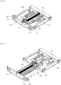
- FIG. 1 is a perspective view showing a conventional power device.
- the conventional power device includes a cradle terminal 110 connected to a power line connected to an external power source or a load. Further, the power device includes a cradle 100 fixed to a switchboard, a circuit breaker body 200 mechanically and electrically connected to or disconnected from the terminal 110 of the cradle 100, and a girder 300 and a truck 400 to bring the circuit breaker body 200 to a contact or disconnection position in which the body is mechanically and electrically connected to or disconnected from the terminal 110 of the cradle 100.
- the contact position means a position in which the circuit breaker body 200 approaches the cradle terminal 110 at the maximum level and electrically contacts the terminal 110.
- the disconnection position means a position in which the circuit breaker body 200 is spaced from the cradle terminal 110 by the maximum spacing and thus is electrically disconnected from the cradle terminal 110.
- a test position means a position corresponding to a process in which the body is being displaced from the contact position to the disconnection position or from the disconnection position to the contact position.
- FIG. 2 and FIG. 3 are perspective views showing the girder 300 and the truck 400 according to the disconnection position and the contact position in FIG. 1 , respectively.
- FIG. 4 shows cross-sectional views of the girder 300 and the truck 400 according to disconnection, test, and contact positions in the conventional power device, respectively.
- the girder 300 includes a pair of handle bars 310 formed on a front face thereof, support ribs 320 respectively formed at both opposing sides thereof, and a spindle 330 having one end rotatably coupled to a center of the front face thereof, and a switch actuation bar 340 formed on one side of the spindle 330.
- the truck 400 includes a plurality of wheels 410 formed at each of both opposing sides thereof and a plurality of micro switches 420 actuated by the switch actuation bar 340. As the spindle 330 rotates, a spacing between the truck 400 and the girder 300 is adjusted as shown in FIGS. 2 and 3 .
- the switch actuation bar 340 includes an elongate groove 341 formed to correspond to a movement range of the truck 400, a rear end inclined portion 342 formed at one end of the groove 341, and a top planar portion 343 constituting a top face except for the groove 341 and the rear end inclined portion 342.
- micro switch 420 includes first to third micro switches 421, 422, and 423.
- the first micro switch 421 includes a first contact lever 421a formed on a bottom thereof so as to contact the switch actuation bar 340, and is closest to the girder 300.
- the second micro switch 422 includes a second contact lever 422a formed on a bottom thereof so as to contact the switch actuation bar 340, and is adjacent to a rear end of the first micro switch 421.
- the third micro switch 423 includes a third contact lever 423a formed on a bottom thereof so as to contact the switch actuation bar 340, and is adjacent to a rear end of the truck 400.
- a method for detecting a relative position between the terminal 110 of the cradle 100 and the circuit breaker body 200 using the truck 300 in this conventional power device is as follows.
- the spacing between the truck 400 and the girder 300 becomes minimum at the disconnection position of the conventional power device.
- the distance between the circuit breaker body 200 and the cradle terminal 110 becomes maximum.
- first contact lever 421a is in contact with the top planar portion 343, while each of the second contact lever 422a and the third contact lever 423a is in contact with the groove 341.
- each of the first contact lever 421a and the second contact lever 422a comes into contact with the groove 341.
- the third contact lever 423a passes by the rear end inclined portion 342 and then comes into contact with the top planar portion 343.
- circuit breaker body 200 is in contact with and thus electrically connected to the cradle terminal 110.
- the first contact lever 421a comes into contact with the groove 341, and the second contact lever 422a passes by the rear end inclined portion 342 and comes into contact with the top planar portion 343.
- the spacing the truck 400 and the girder 300 is adjusted in a state in which the switch actuation bar 340 is coupled to the girder 300.
- the position of the circuit breaker body 200 is detected based on whether the plurality of micro switches 420 fixedly installed on the truck 400 are in contact with the switch actuation bar 340.
- the position of the circuit breaker body 200 may be detected at each of the disconnection, test, and contact positions of the power device.
- a varying distance between the circuit breaker body 200 and the cradle terminal 110 cannot be detected.
- the position of the circuit breaker body 200 cannot be accurately detected due to frequent occurrence of the deformation of or the damage to the coupling portion between the micro switch 420 and the truck 400.
- a purpose of the present disclosure is to provide a power device for continuously detecting extended and retracted positions of a circuit breaker body which is capable of linearly detecting a position of the circuit breaker body over an entirety of a movement range.
- a purpose of the present disclosure is to provide a power device for continuously detecting extended and retracted positions of a circuit breaker body in which physical contact between components in order to detect the position of the circuit breaker body is minimized.
- the present disclosure provides a power device for continuously detecting extended and retracted positions of a circuit breaker body, wherein the power device for continuously detecting each of extended and retracted positions of the circuit breaker body includes a cradle having a cradle terminal; a circuit breaker body mechanically and electrically connected to or disconnected from the cradle terminal; and a girder and a truck as transporting means for moving the circuit breaker body to a contact or disconnection position with or from the cradle terminal, wherein the power device is capable of linearly detecting a position of the circuit breaker body over an entirety of a movement range.
- the power device includes: a position detected area portion formed on at least one of both opposing side faces of the circuit breaker body; and a sensor module fixed to at least one of both opposing inner side faces of the cradle, wherein the sensor module includes at least one sensor facing the position detected area portion so to detect a displaced position of the position detected area portion and thus to detect a position of the circuit breaker body, based on the detected displaced position.
- the position detected area portion may include at least one of: a position sticker having a shade varying in a movement direction of the truck; a plurality of position protrusions, wherein at least one of a number, a shape, or a position thereof varies in the movement direction of the truck; or a position inclined portion having one face inclined downwardly or upwardly in the truck movement direction.
- the senor may include at least one of a non-contact type sensor or a contact type sensor.
- the contact type sensor may be embodied as a roller-type sensor having a roller rotating while being in contact with a side face of the circuit breaker body.
- the senor may include a contact type sensor configured to contact the position inclined portion and to detect a varying height of the position inclined portion and to detect the position of the circuit breaker body based on the detected varying height.
- the device may further include a cleaner disposed in front or rear of the sensor module so as to remove dust or foreign substance deposited on the position detected area portion.
- the power device for continuously detecting extended and retracted positions may linearly detect the position of the circuit breaker body over an entirety of a movement range, thereby achieving an advantage of being able to identify an accurate position of the circuit breaker body in real time.
- first element or layer when a first element or layer is referred to as being present "on” or “beneath” a second element or layer, the first element may be disposed directly on or beneath the second element or may be disposed indirectly on or beneath the second element with a third element or layer being disposed between the first and second elements or layers.
- a and/or B includes any and all combinations of one or more of A and B unless otherwise specified.
- C to D this means C inclusive to D inclusive unless otherwise specified.
- the same reference numerals are allocated to the same components of the power device for continuously detecting the extended and retracted positions of the circuit breaker body according to the present disclosure as those of the conventional power device.
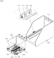
- FIG. 5 is a perspective view showing a state before a circuit breaker body is mounted to a cradle in a power device for continuously detecting extended and retracted positions according to an embodiment of the present disclosure.
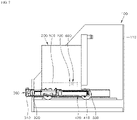
- FIG. 6 to FIG. 8 are side cross-sectional views respectively at disconnection, operation, and contact positions in a power device for continuously detecting extended and retracted positions according to an embodiment of the present disclosure.
- the power device for continuously detecting the extended and retracted positions of the circuit breaker body includes the cradle 100 having the cradle terminal 110 connected to a power line connected to an external power source or a load, and fixed to a switchboard, the circuit breaker body 200 that is mechanically and electrically connected to or disconnected from the terminal 110 of the cradle 100, and the girder 300 and the truck 400 as a transport device that moves the circuit breaker body 200 to a disconnection or contact position.
- the circuit breaker body 200 is fixedly mounted to the truck 400. Accordingly, as the truck 400 moves, a spacing between the circuit breaker body 200 and the cradle terminal 110 is adjusted.
- the circuit breaker includes the circuit breaker body, 200 the girder 300 and the truck 400.
- the disconnection position means a position in which the circuit breaker body 200 is spaced from the cradle terminal 110 by the maximum spacing and thus is electrically disconnected from the cradle terminal 110.
- the disconnection position means a state in which the spacing between the girder 300 and the truck 400 is minimized as shown in FIG. 6 .
- the contact position means a position in which the circuit breaker body 200 approaches the cradle terminal 110 at the maximum level and electrically contacts the terminal 110.
- the contact position means a state in which the spacing between the girder 300 and the truck 400 is maximized as shown in FIG. 8 .
- the operation position means a state in which the spacing between the girder 300 and the truck 400 is adjusted in a process in which the body is being displaced from the contact position to the disconnection position or from the disconnection position to the contact position, as shown in FIG. 7 .
- the girder 300 includes a pair of handle bars 310 formed on a front face thereof, support ribs 320 respectively formed at both opposing sides thereof, and a spindle 330 having one end rotatably coupled to a center of the front face thereof.
- the handle bar 310 may refer to a part gripped by an operator when the girder 300 and the truck 400 are mounted to or disconnected from the cradle 100 and be formed in various shapes.
- the girder 300 is fixed to the cradle 100 while each of the support ribs 320 is inserted into and fixed to each of both opposing sides of the cradle 100.
- the spindle 330 is coupled to the truck 400 such that one end of the spindle is coupled to a central portion of the girder 300 and the other end thereof faces the cradle terminal 110.
- the spacing between the girder 300 and the truck 400 is adjusted.
- the rotation of the spindle 330 may be achieved by an operator inserting a handle to a hole formed in a front face of the girder and manually rotating the handle, or may be automatically achieved by a driving motor.
- the power device for continuously detecting extended and retracted positions includes a position detected area portion 500 formed on a side face of the circuit breaker body 200, and a sensor module 600 fixed to an inner side face of the cradle 100, wherein the sensor module includes a non-contact type sensor 610 facing the position detected area portion 500 to detect a displaced position of the position detected area portion 500 and thus detect a position of the circuit breaker body 200 based on the detected displaced position.
- the position detected area portion 500 is positioned such that an end thereof adjacent to the cradle terminal 110 faces the sensor module 600 at the disconnection position, and an end thereof adjacent to the girder 300 faces the sensor module 600 at the contact position.
- the position detected area portion 500 is formed on a side face of the circuit breaker body 200 and has a length proportional to a movement distance of the truck 400.
- a pair of position detected area portions 500 may be respectively formed on left and right side faces of the circuit breaker body 200 so as to be symmetrical with each other.
- a pair of sensor modules 600 may be respectively disposed on both opposing side faces of the cradle 100.
- FIG. 9 is a perspective view showing a position detected area portion in a power device for continuously detecting extended and retracted positions according to an embodiment of the present disclosure.
- the position detected area portion 500 may extend along the movement range of the truck 400 as described above. More preferably, the position detected area portion 500 may be embodied as a position sticker 510 having a shade varying depending on a position, such as a gradation sticker.
- the position detected area portion 500 may have a groove defined therein having a depth equal to or larger than a thickness of the position sticker 510.
- the position sticker 510 may be prevented from being redisplaced from the circuit breaker body 200.
- the position sticker 510 may be embodied as a gradation tape formed so that a portion thereof adj acent to the girder 300 is darker and a portion thereof adj acent to the cradle terminal 110 is brighter as shown in (a) of FIG. 9 .
- the position sticker 510 may be embodied as a gradation tape formed so that a portion thereof adj acent to the girder 300 is brighter and a portion thereof adj acent to the cradle terminal 110 is darker.
- the position sticker 510 may be embodied as a gradation tape formed so that a portion thereof adjacent to the girder 300 is brighter and a portion thereof adjacent to the cradle terminal 110 is brighter, while a middle portion thereof is darker.
- the position sticker 510 may be divided into at least two portions.
- the position sticker 510 may be embodied as a gradation tape having an area size varying in a movement direction of the truck 400 as shown in (b) of FIG. 9 .
- the position detected area portion 500 may embodied as a position inclined portion 520 as shown in (c) of FIG. 9 .
- a distance between a top face of the position inclined portion 520 and the sensor module 600 may vary.
- the position inclined portion 520 may be formed such that a spacing between the cradle 100 and the position inclined portion 520 gradually decreases or increases as the position inclined portion 520 extends along a direction from one end to the other end thereof.
- position inclined portion 520 may be formed so as to protrude beyond a side face of the circuit breaker body 200 or so as to be recessed downwardly of a side face of the circuit breaker body 200.
- the position sticker 510 may be attached to a top face of the position inclined portion 520.
- the position detected area portion 500 may include a plurality of position protrusions 530 arranged and spaced from each other by a predefined spacing as shown in (d) of FIG. 9 .
- the numbers or shapes of the position protrusions 530 may vary in the movement direction of the truck 400 so that the position of the circuit breaker body 200 may be detected by the sensor module 600.
- the position detected area portion 500 may include a combination of the position protrusions 530 and the position tape 510.
- the non-contact type sensor 610 may be embodied as each of various sensors capable of detecting a shade or a distance of the position detected area portion 500 while being not in contact with the position detected area portion 500.
- the non-contact type sensor 610 may be embodied as an optical sensor and may be configured to detect a shade, a distance, a shape, etc. of a predefined area in the position detected area portion 510.
- the non-contact type sensor 610 may sense the movement distance of the position detected area portion 500 even in the operation position corresponding to the process in which the circuit breaker body 200 moves from the contact position to the disconnection position, or moves from the disconnection position to the contact position.
- the position of the circuit breaker body 200 may be linearly detected.
- the non-contact type sensor 610 is embodied as the optical sensor, it is preferable that the non-contact type sensor 610 is positioned into a recessed space defined in the sensor module 600 in order to minimize a detection error due to a shade caused by each of other components.
- the power device for continuously detecting extended and retracted positions may linearly detect the position of the circuit breaker body 200 throughout the entire movement range thereof and thus may determine the exact position of the circuit breaker body 200 in real time.
- the sensor module 600 may include a contact type sensor 620.
- the contact type sensor 620 may contact the position detected area portion 500 via an FPCB (Flexible Printed Circuit Board) or an elastic member.
- FPCB Flexible Printed Circuit Board
- the contact type sensor 620 may be embodied as a roller type sensor in which a roller may rotate under the movement of the circuit breaker body 200 while being in contact with a side face of the circuit breaker body 200.
- the contact type sensor 620 when the contact type sensor 620 is embodied as the roller type sensor, the sensor 620 may detect a rotation angle of the roller and detect the position of the circuit breaker body 200 based on the detected rotation angle.
- the contact type sensor 620 may contact the position inclined portion 520 and may detect a varying height of the position inclined portion 520 and thus detect the position of the circuit breaker body 200 based on the varying height.
- both the non-contact type sensor 610 and the contact type sensor 620 may linearly detect the position of the circuit breaker body 200 throughout the entire movement range thereof simultaneously.
- the exact position of the circuit breaker body 200 may be determined in real time.
- the cradle terminal 110 which the circuit breaker body 200 electrically and mechanically contacts may include terminals of three-phases (R, S, T). In this case, when contacts between the circuit breaker body 200 and these terminals 110 fail to occur concurrently, damage to the power device and power accident may occur.
- the power device for continuously detecting extended and retracted positions may be configured such that the position detected area portion 500 is formed on each of both opposing side faces of the circuit breaker body 200 and accordingly, the sensor module 600 is formed on each of both opposing inner side faces of the cradle 100 so that contacts or disconnections between the circuit breaker body 200 and these terminals 110 occur concurrently.
- a monitoring unit (not shown) for generating an alarm when two positions of the circuit breaker body 200 respectively detected by the two sensor modules 600 do not coincide with each other may be further included in the power device.
- the circuit breaker body 200 may contact or may be disconnected from the cradle terminal 110 to prevent device damage and power accidents.
- the position detected area portion 500 may be formed on an inner side face of the cradle 100, while the sensor module 600 may be disposed on a side face of the circuit breaker body 200.
- the sensor module 600 is disposed on the inner side face of the cradle 100 as described above such that connection, control, and inspection of the sensor module 600 is facilitated.
- the position detected area portion 500 may be formed on an inner side face of the cradle 100, and the sensor module 600 may be disposed on the side face of the breaker body 200, according to a design specification.
- the power device for continuously detecting extended and retracted positions may further include a cleaner 700 configured to remove dust or foreign matter deposited on the position detected area portion 500.
- the cleaner 700 may be disposed in front or rear of the sensor module 600 as shown in FIG. 5 .
- the cleaner 700 may be formed in a shape such as a brush or a roller and may remove dust or foreign substances deposited on the position detected area portion 500 under the movement of the circuit breaker body 200 while being in contact with the position detected area portion 500. This may minimize a detection error of the sensor module 600 due to the dust or foreign substances.
- the cleaner 700 is installed in front of the sensor module 600.
- the cleaner 700 When the cleaner 700 is adjacent to the cradle terminal 110, arc may occur such that the cleaner 700 may be damaged or an electrical problem may occur. Thus, the cleaner 700 may be spaced from the cradle terminal 110 by a maximum spacing.
- the position detected area portion 500 may be formed on the cradle 100, and the sensor module 600 may be formed on the circuit breaker body 200.
Landscapes
- Engineering & Computer Science (AREA)
- Power Engineering (AREA)
- Breakers (AREA)
- Trip Switchboards (AREA)
- Current-Collector Devices For Electrically Propelled Vehicles (AREA)
- Control Or Security For Electrophotography (AREA)
- Details Of Connecting Devices For Male And Female Coupling (AREA)
Applications Claiming Priority (2)
| Application Number | Priority Date | Filing Date | Title |
|---|---|---|---|
| KR1020200041146A KR102378389B1 (ko) | 2020-04-03 | 2020-04-03 | 인입출 위치를 연속적으로 검출하기 위한 전력기기 |
| PCT/KR2021/003874 WO2021201538A1 (fr) | 2020-04-03 | 2021-03-29 | Dispositif de puissance permettant de détecter en continu des positions d'entrée et de sortie |
Publications (2)
| Publication Number | Publication Date |
|---|---|
| EP4131316A1 true EP4131316A1 (fr) | 2023-02-08 |
| EP4131316A4 EP4131316A4 (fr) | 2023-09-06 |
Family
ID=77927958
Family Applications (1)
| Application Number | Title | Priority Date | Filing Date |
|---|---|---|---|
| EP21780263.6A Pending EP4131316A4 (fr) | 2020-04-03 | 2021-03-29 | Dispositif de puissance permettant de détecter en continu des positions d'entrée et de sortie |
Country Status (6)
| Country | Link |
|---|---|
| US (1) | US12009642B2 (fr) |
| EP (1) | EP4131316A4 (fr) |
| JP (1) | JP7458501B2 (fr) |
| KR (1) | KR102378389B1 (fr) |
| CN (1) | CN115335946B (fr) |
| WO (1) | WO2021201538A1 (fr) |
Families Citing this family (2)
| Publication number | Priority date | Publication date | Assignee | Title |
|---|---|---|---|---|
| KR102364757B1 (ko) * | 2020-04-03 | 2022-02-17 | 엘에스일렉트릭(주) | 전력기기의 모니터링 시스템 |
| CN119864730B (zh) * | 2025-03-21 | 2025-07-25 | 红光电气集团有限公司 | 一种铠装移开式开关柜 |
Family Cites Families (28)
| Publication number | Priority date | Publication date | Assignee | Title |
|---|---|---|---|---|
| US5684282A (en) * | 1996-03-22 | 1997-11-04 | General Electric Company | Drawout circuit breaker, position switch and reset arrangements |
| KR100269400B1 (ko) * | 1997-12-27 | 2000-10-16 | 이종수 | 진공차단기용포지션스위치 |
| JP2000213916A (ja) * | 1999-01-25 | 2000-08-04 | Shimizu Corp | 変位計測方法 |
| KR200340100Y1 (ko) * | 2003-08-19 | 2004-01-31 | 현대중공업 주식회사 | 배전반용 진공차단기 위치의 외부 표시장치 |
| JP4876233B2 (ja) * | 2004-03-22 | 2012-02-15 | 多摩川精機株式会社 | 位置検出器および被検出体 |
| TWI312859B (en) * | 2006-11-22 | 2009-08-01 | Asia Optical Co Inc | Distant measurement systems and distant measurement methods thereof |
| KR101106899B1 (ko) * | 2009-10-07 | 2012-01-25 | 엘에스산전 주식회사 | 포지션 스위치 및 이를 구비한 회로 차단기 |
| US8304672B2 (en) * | 2009-12-21 | 2012-11-06 | Schneider Electric USA, Inc. | Wireless remote racking mechanism |
| JP2012193973A (ja) * | 2011-03-15 | 2012-10-11 | Toyota Auto Body Co Ltd | 位置検出構造 |
| KR101466030B1 (ko) * | 2011-06-22 | 2014-12-01 | 엘에스산전 주식회사 | 인출형 회로차단기의 위치검출장치 |
| KR200462421Y1 (ko) | 2011-09-30 | 2012-09-10 | 엘에스산전 주식회사 | 진공 차단기의 거더와 트럭 어셈블리 |
| KR101903743B1 (ko) * | 2012-05-22 | 2018-10-04 | 삼성디스플레이 주식회사 | 표시 장치, 표시 장치의 캘리브레이션 방법, 및 표시 장치의 표시 방법 |
| EP2682971B1 (fr) * | 2012-07-03 | 2016-11-30 | ABB Schweiz AG | Dispositif permettant d'indiquer l'état d'un appareil de commutation |
| JP2014033590A (ja) * | 2012-08-06 | 2014-02-20 | Chugoku Electric Power Co Inc:The | スイッチギヤ |
| CN202978079U (zh) * | 2012-12-07 | 2013-06-05 | 福建森达电气有限公司 | 一种智能型真空断路器 |
| US9673595B2 (en) * | 2013-10-31 | 2017-06-06 | Eaton Corporation | Withdrawable contactor trucks with integral motorized levering-in, related switchgear, kits and methods |
| KR101604281B1 (ko) * | 2014-01-28 | 2016-03-17 | 엘에스산전 주식회사 | 회로차단기의 접지대차 |
| WO2017011536A1 (fr) * | 2015-07-13 | 2017-01-19 | Abb Schweiz Ag | Indicateur mécanique de position dans un bâti |
| CN107421450B (zh) * | 2017-06-29 | 2023-07-04 | 罗琪 | 光学位移测量器及位移测量方法 |
| CN107275970A (zh) * | 2017-07-12 | 2017-10-20 | 中科电力装备集团有限公司 | 一种万能式断路器 |
| US11875956B2 (en) * | 2019-02-18 | 2024-01-16 | Ls Electric Co., Ltd. | Contact point monitoring device for vacuum circuit breaker, and vacuum circuit breaker comprising same |
| CN109861125A (zh) * | 2019-04-01 | 2019-06-07 | 银川市立恒电气设备有限公司 | 本安型智能电气开关柜 |
| WO2020204397A1 (fr) * | 2019-04-05 | 2020-10-08 | 엘에스일렉트릭(주) | Dispositif de surveillance de point de contact pour disjoncteur à vide, et procédé de correction réalisé à l'aide dudit dispositif |
| KR102683376B1 (ko) * | 2019-04-05 | 2024-07-08 | 엘에스일렉트릭(주) | 진공차단기용 접점 감시 장치 및 이를 갖는 진공차단기 |
| JP7263623B2 (ja) * | 2019-09-10 | 2023-04-24 | エルエス、エレクトリック、カンパニー、リミテッド | 真空遮断器用の接点監視装置、及びこれを有する真空遮断器 |
| KR102423582B1 (ko) * | 2020-04-03 | 2022-07-20 | 엘에스일렉트릭(주) | 인입출 위치를 연속적으로 검출하기 위한 전력기기 |
| KR102378392B1 (ko) * | 2020-04-03 | 2022-03-24 | 엘에스일렉트릭(주) | 전력 기기용 인입출 위치 검출 장치 및 이를 갖는 인입출 모니터링 시스템 |
| KR102364757B1 (ko) * | 2020-04-03 | 2022-02-17 | 엘에스일렉트릭(주) | 전력기기의 모니터링 시스템 |
-
2020
- 2020-04-03 KR KR1020200041146A patent/KR102378389B1/ko active Active
-
2021
- 2021-03-29 WO PCT/KR2021/003874 patent/WO2021201538A1/fr not_active Ceased
- 2021-03-29 JP JP2022558207A patent/JP7458501B2/ja active Active
- 2021-03-29 EP EP21780263.6A patent/EP4131316A4/fr active Pending
- 2021-03-29 CN CN202180025435.XA patent/CN115335946B/zh active Active
- 2021-03-29 US US17/916,715 patent/US12009642B2/en active Active
Also Published As
| Publication number | Publication date |
|---|---|
| JP7458501B2 (ja) | 2024-03-29 |
| KR102378389B1 (ko) | 2022-03-24 |
| CN115335946A (zh) | 2022-11-11 |
| US20230144848A1 (en) | 2023-05-11 |
| KR20210123686A (ko) | 2021-10-14 |
| EP4131316A4 (fr) | 2023-09-06 |
| JP2023519327A (ja) | 2023-05-10 |
| US12009642B2 (en) | 2024-06-11 |
| WO2021201538A1 (fr) | 2021-10-07 |
| CN115335946B (zh) | 2026-04-28 |
Similar Documents
| Publication | Publication Date | Title |
|---|---|---|
| EP4131679A1 (fr) | Dispositif d'alimentation pour la détection continue de positions d'entrée et de sortie | |
| EP4131316A1 (fr) | Dispositif de puissance permettant de détecter en continu des positions d'entrée et de sortie | |
| EP0440330B1 (fr) | Connecteur | |
| KR20080034985A (ko) | 패치 코드 끝단의 연결을 검지하는 시스템 및 방법 | |
| EP4131317A1 (fr) | Système de surveillance dispositif d'alimentation | |
| KR102540099B1 (ko) | 인쇄회로기판용 하부 진공흡착장치 | |
| EP3929957B1 (fr) | Dispositif de détection de mouvement pour disjoncteur à vide et disjoncteur à vide le comprenant | |
| CA2576934A1 (fr) | Contenant pour materiel d'impression | |
| CN103066452A (zh) | 连接器 | |
| CN106610746A (zh) | 一种移动终端及其控制方法 | |
| CA2334140A1 (fr) | Mecanisme de detection de cellule | |
| US7705252B2 (en) | Rotary control device | |
| EP1194786B1 (fr) | Dispositif de commande automatique de raccordement de lignes pour haute tension electrique | |
| CN113237414B (zh) | 一种显示模组、电子设备及对位精度的检测方法 | |
| KR102683644B1 (ko) | 진공차단기용 접점 감시 장치 및 이를 갖는 진공차단기 | |
| US20080017508A1 (en) | Non-contact type single side probe structure | |
| KR100858725B1 (ko) | 커넥터 삽입력 측정장치 및 방법 | |
| JPH08222069A (ja) | 押しボタンスイッチ | |
| JPS6331888B2 (fr) | ||
| JPH10233428A (ja) | 半導体製造装置 | |
| CN203812398U (zh) | 一种两侧为弹性形变结构的按压套式按压开关 | |
| JP2002101246A (ja) | 画像読取り装置 | |
| JPH0577267U (ja) | メッキ装置のワーク検出装置 | |
| JPH0765265A (ja) | ワイヤレス火災感知器 |
Legal Events
| Date | Code | Title | Description |
|---|---|---|---|
| STAA | Information on the status of an ep patent application or granted ep patent |
Free format text: STATUS: THE INTERNATIONAL PUBLICATION HAS BEEN MADE |
|
| PUAI | Public reference made under article 153(3) epc to a published international application that has entered the european phase |
Free format text: ORIGINAL CODE: 0009012 |
|
| STAA | Information on the status of an ep patent application or granted ep patent |
Free format text: STATUS: REQUEST FOR EXAMINATION WAS MADE |
|
| 17P | Request for examination filed |
Effective date: 20221007 |
|
| AK | Designated contracting states |
Kind code of ref document: A1 Designated state(s): AL AT BE BG CH CY CZ DE DK EE ES FI FR GB GR HR HU IE IS IT LI LT LU LV MC MK MT NL NO PL PT RO RS SE SI SK SM TR |
|
| DAV | Request for validation of the european patent (deleted) | ||
| DAX | Request for extension of the european patent (deleted) | ||
| A4 | Supplementary search report drawn up and despatched |
Effective date: 20230809 |
|
| RIC1 | Information provided on ipc code assigned before grant |
Ipc: H02B 11/10 20060101ALI20230803BHEP Ipc: H02B 11/127 20060101ALI20230803BHEP Ipc: H01H 71/06 20060101ALI20230803BHEP Ipc: H01H 71/04 20060101ALI20230803BHEP Ipc: H01H 71/52 20060101AFI20230803BHEP |