EP4131368B1 - Modulgehäuse aus kunststoff mit eingebettetem kühlkörper - Google Patents
Modulgehäuse aus kunststoff mit eingebettetem kühlkörper Download PDFInfo
- Publication number
- EP4131368B1 EP4131368B1 EP22186872.2A EP22186872A EP4131368B1 EP 4131368 B1 EP4131368 B1 EP 4131368B1 EP 22186872 A EP22186872 A EP 22186872A EP 4131368 B1 EP4131368 B1 EP 4131368B1
- Authority
- EP
- European Patent Office
- Prior art keywords
- screw
- cooling element
- module housing
- sleeve
- heat sink
- Prior art date
- Legal status (The legal status is an assumption and is not a legal conclusion. Google has not performed a legal analysis and makes no representation as to the accuracy of the status listed.)
- Active
Links
Images


Classifications
-
- H—ELECTRICITY
- H05—ELECTRIC TECHNIQUES NOT OTHERWISE PROVIDED FOR
- H05K—PRINTED CIRCUITS; CASINGS OR CONSTRUCTIONAL DETAILS OF ELECTRIC APPARATUS; MANUFACTURE OF ASSEMBLAGES OF ELECTRICAL COMPONENTS
- H05K7/00—Constructional details common to different types of electric apparatus
- H05K7/20—Modifications to facilitate cooling, ventilating, or heating
- H05K7/20845—Modifications to facilitate cooling, ventilating, or heating for automotive electronic casings
- H05K7/20854—Heat transfer by conduction from internal heat source to heat radiating structure
-
- H—ELECTRICITY
- H05—ELECTRIC TECHNIQUES NOT OTHERWISE PROVIDED FOR
- H05K—PRINTED CIRCUITS; CASINGS OR CONSTRUCTIONAL DETAILS OF ELECTRIC APPARATUS; MANUFACTURE OF ASSEMBLAGES OF ELECTRICAL COMPONENTS
- H05K7/00—Constructional details common to different types of electric apparatus
- H05K7/20—Modifications to facilitate cooling, ventilating, or heating
- H05K7/2039—Modifications to facilitate cooling, ventilating, or heating characterised by the heat transfer by conduction from the heat generating element to a dissipating body
- H05K7/20409—Outer radiating structures on heat dissipating housings, e.g. fins integrated with the housing
-
- H—ELECTRICITY
- H10—SEMICONDUCTOR DEVICES; ELECTRIC SOLID-STATE DEVICES NOT OTHERWISE PROVIDED FOR
- H10W—GENERIC PACKAGES, INTERCONNECTIONS, CONNECTORS OR OTHER CONSTRUCTIONAL DETAILS OF DEVICES COVERED BY CLASS H10
- H10W40/00—Arrangements for thermal protection or thermal control
- H10W40/60—Securing means for detachable heating or cooling arrangements, e.g. clamps
- H10W40/611—Bolts or screws
Definitions
- the invention relates to a module housing made of plastic, in particular of duroplast, with an embedded heat sink, which can be mounted on a heat sink.
- thermoset housings Electrical and electronic devices or modules are often housed in thermoset housings. These, like thermoplastic housings, have the advantage over metal housings of being lightweight, offering good electrical insulation properties, and being able to be manufactured with a very high surface quality and in a wide variety of shapes using primary molding.
- the housing can be a separate structure enclosing internal device or module components, or it can be a mass of material directly enclosing the device or module components.
- Housing components such as screw-on sleeves, which must be made of metal, or device or module components that must have an interface with the environment, such as a heat sink, can be inserted into the mold during housing manufacture and molded or pressed in with the plastic.
- thermoset housings are more dimensionally stable and heat-resistant, which is particularly advantageous for devices and modules that generate significant heat during operation.
- thermoset has the disadvantage of being brittle and therefore easily breakable.
- EP 2 175 708 A1 discloses an electronic module with a heat sink.
- the electronic module comprises a housing that is attached to a conductive plate by means of a screw connection.
- EP 1 006 766 A1 shows an electronic device with a two-part housing for accommodating an electronic circuit.
- module housings in particular for electronic circuit modules, made of thermoset.
- These circuit modules essentially contain a circuit board populated with electronic components and a heat sink to dissipate the heat generated by the electronic components.
- a heat sink In order to dissipate the heat absorbed by the heat sink through thermal conduction, it must be brought into good surface contact with an external heat sink, which requires the application of a pressure force and a low flatness tolerance. The better the surface contact, the faster the heat is removed from the heat sink.
- the relative position of the heat sink within the module housing is determined by the design of the circuit module, in which the heat sink is generally arranged in relation to the components in such a way that the heat sink is connected to the heat sink at the front of the module housing either directly or indirectly via a heat conductor that is as short as possible.
- the heat sink can be arranged in a wide variety of relative positions within the module housing towards its edge. Facing away from the circuit module, facing outwards, the heat sink has a free, embedded flat surface all around, which is brought into contact with a carrier serving as an external heat sink by screwing the module housing directly or indirectly to the carrier via two screw sleeves that are also embedded in the module housing.
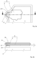
- Fig. 1a and 1b Such a module housing is shown according to the state of the art.
- the two screw sleeves are arranged relative to the heat sink in such a way that an imaginary straight line between them runs across the exposed flat surface of the heat sink.
- the heat sink typically has a contact surface that is sized and shaped to match the free flat surface of the heat sink.
- the screw sleeves each embedded at a distance from the heat sink, are positioned opposite screw bushings when the heat sink is properly seated on the heat sink. These can be located in the support serving as the heat sink or in components firmly attached to the support.
- the contact surfaces on the support, one for the heat sink and the other for the screw sleeves are dimensioned or toleranced in such a way that, when the screws are tightened through the screw sleeves into the support, a pressing force is exerted by the heat sink on the support. This creates bending stresses in the module housing along the imaginary connecting line, which can lead to cracking in brittle plastic.
- the object of the invention is to improve a module housing made of plastic with an embedded heat sink so that it can be attached to a carrier free from bending stresses.
- a module housing made of plastic, in particular of duroplast, with an embedded heat sink and at least one embedded screw-on sleeve, which has a collar with an outwardly exposed screw-on surface and is provided for mounting the module housing on a carrier serving as an external heat sink, in that the heat sink and the at least one screw-on sleeve are connected to one another to form a monolithic body, whereby heat is extracted from the heat sink by heat conduction to the carrier, at least via the screw-on surface.
- a pressure force is transmitted into the carrier via the screw-on surface of the at least one screw-on sleeve, which causes an equally large counterforce.
- This counterforce is absorbed by the monolithic body formed by the heat sink and the at least one screw-on sleeve. Since the heat sink bends at most negligibly as a result of the counterforce, which can have a different effect on the carrier depending on how the monolithic body is applied to the carrier, at most negligible bending stresses are also introduced into the plastic.
- Monolithic means that the body consists of a single, indivisible unit.
- the carrier can be designed so that only the screw-on surface comes into contact with the carrier, even if the heat sink is not set back relative to the screw-on surface.
- Exclusive heat removal by heat conduction via the screw-on surface has the particular advantage that to minimize the flatness tolerance, only the screw-on surface needs to undergo final surface processing.
- the cross-section of a monolithic connection is adapted in its height and/or width to the height of the heat sink and the outer diameter of the screw sleeve.
- the screw-on sleeve is completely connected to the heat sink over a height of the heat sink in the direction of a cylinder axis of the screw-on sleeve, whereby a cross-section of the monolithic connection between the heat sink and the screw-on sleeve in the direction of the height of the heat sink is optimized for heat extraction.
- the screw-on sleeve is connected to the heat sink over a width that corresponds at least to the outer diameter of the screw-on sleeve, whereby a cross-section of the monolithic connection between the heat sink and the screw-on sleeve is optimized for heat extraction in the direction of the width of the heat sink.
- the screwing surface is preferably designed to be largely ring-shaped.
- the screwing surface preferably has an outer diameter that is at least twice as large as the inner diameter of the screwing surface.
- a module housing according to the invention can preferably be used in an electrical assembly.
- the electrical assembly is an inverter and/or a transmission.
- an electrical assembly with a module housing according to the invention is used in a motor vehicle, in particular an electric vehicle.
- a module housing according to the invention in the automotive industry.
- a module housing according to the invention is made of plastic, preferably of duroplast.
- a heat sink 1 and at least one screw-on sleeve 2 are embedded in it.
- heat is extracted from the heat sink 1 directly via a free base area of the heat sink (thermal interface) and the at least one screw-on sleeve 2 only functions as a mechanical interface
- the at least one screw-on sleeve 2 of a module housing according to the invention represents both a mechanical and a thermal interface.
- the at least one screw-on sleeve 2 is connected to the heat sink 1, forming a monolithic body 0.
- the monolithic body has exactly one screw-on sleeve 2, with a collar 21 having an outwardly exposed screw-on surface 211, which comes into contact with a support 3 serving as an external heat sink during assembly of the module housing.
- the screw-on surface 211 is an integral part of a flat base surface that extends over the entire monolithic body 0.
- the module housing is mounted, as shown, on a carrier 3 which has a contact surface 31 facing the module housing which is limited to the dimensions of the screwing surface, heat is extracted by heat conduction, but force is also introduced exclusively via the screwing surface 211.
- the screwing surface is finally manufactured to be highly flat.
- the contact surface 31 on the carrier 3 is dimensioned larger, up to a size equal to the base area of the monolithic body 0 (not shown in the drawings), heat is extracted by heat conduction across the entire base area, which, however, places high demands on the flatness of the base area and the contact surface 31.
- one or two additional screwing sleeves 2 formed in the monolithic body can be provided.
Landscapes
- Physics & Mathematics (AREA)
- Thermal Sciences (AREA)
- Engineering & Computer Science (AREA)
- Microelectronics & Electronic Packaging (AREA)
- Cooling Or The Like Of Electrical Apparatus (AREA)
- Cooling Or The Like Of Semiconductors Or Solid State Devices (AREA)
Description
- Die Erfindung betrifft ein Modulgehäuse aus Kunststoff, insbesondere aus Duroplast, mit einem eingebetteten Kühlkörper, das an einer Wärmesenke montierbar ist.
- Elektrische und elektronische Geräte oder Module werden häufig mit einem Gehäuse aus Duroplast versehen. Diese haben ebenso wie Gehäuse aus Thermoplast gegenüber metallischen Gehäusen den Vorteil, dass sie ein nur geringes Gewicht haben, gute elektrische Isolationseigenschaften aufweisen und mit einer sehr hohen Oberflächenqualität in einer hohen Formenvielfalt durch Urformen herstellbar sind.
- Das Gehäuse kann als separates Gebilde innenliegende Geräte- bzw. Modulbestandteile einschließen oder aber als Materialmasse die Geräte- bzw. Modulbestandteile, unmittelbar umhüllen. Gehäusebestandteile, wie z. B. Anschraubhülsen, die aus Metall sein müssen oder aber Geräte- bzw. Modulbestandteile, die eine Schnittstelle zur Umgebung aufweisen müssen, wie z. B. ein Kühlkörper, können beim Herstellen des Gehäuses in das Formwerkzeug eingelegt und mit dem Gießen oder Verpressen des Kunststoffes eingegossen bzw. eingepresst werde.
- Im Vergleich zu Gehäusen aus Thermoplast sind solche aus Duroplast formbeständiger und wärmefest, was insbesondere für Geräte und Module von Vorteil ist, deren Betrieb mit einer hohen Wärmeentwicklung von statten geht. Für Anwendungen bei denen das Gehäuse mechanischen Belastungen unterliegen kann, hat Duroplast allerdings den Nachteil, dass es spröde und daher leicht zerbrechlich ist.
-
EP 2 175 708 A1 offenbart ein Elektronikmodul mit einer Wärmesenke. Das Elektronikmodul umfasst ein Gehäuse, welches an eine leitfähige Platte mittels einer Schraubverbindung angeordnet wird. -
EP 1 006 766 A1 zeigt eine elektronische Vorrichtung mit einem zweiteiligen Gehäuse zur Aufnahme einer elektronischen Schaltung. - In
DE 20 2017 104 164 U1 ist ein Montagesystem und eine Kühlvorrichtung für COM-Module gezeigt. - Es ist aus der Praxis bekannt Gehäuse für Module (nachfolgend Modulgehäuse) insbesondere für elektronische Schaltungsmodule, aus Duroplast auszuführen. Diese Schaltungsmodule enthalten im Wesentlichen eine mit elektronischen Bauelementen bestückte Leiterplatte und einen Kühlkörper, zur Abführung der durch die elektronischen Bauelemente erzeugten Wärme. Um die vom Kühlkörper aufgenommene Wärme durch Wärmeleitung von diesem abzuführen, muss er in einen guten Flächenkontakt mit einer externen Wärmesenke gebracht werden, was die Wirkung einer Andruckkraft und eine nur geringe Ebenheitstoleranz erfordert. Je besser der Flächenkontakt ist, desto schneller wird die Wärme dem Kühlkörper entzogen.
- Die Relativlage des Kühlkörpers innerhalb des Modulgehäuses ist bestimmt vom Design des Schaltungsmoduls, bei dem der Kühlkörper zu den Bauelementen in der Regel so angeordnet ist, dass der Kühlkörper stirnseitig des Modulgehäuses entweder unmittelbar oder mittelbar über einen möglichst kurzen Wärmeleiter mit dem Kühlkörper in Verbindung steht. Es ergibt sich daraus, dass der Kühlkörper innerhalb des Modulgehäuses zu dessen Rand hin in verschiedensten Relativlagen angeordnet sein kann. Vom Schaltungsmodul abgewandt, nach außen gerichtet, weist der Kühlkörper eine ringsum eingebettete, freie Planfläche auf, die mit einem als externe Wärmesenke dienenden Träger in Kontakt gebracht wird, indem das Modulgehäuse über zwei, ebenfalls in das Modulgehäuse eingebettete, Anschraubhülsen an dem Träger mittelbar oder unmittelbar verschraubt wird.
- In
Fig. 1a und 1b ist ein solches Modulgehäuse, gemäß dem Stand der Technik, dargestellt. Um eine gute kraftschlüssige Verbindung zwischen dem Kühlkörper und der Wärmesenke herzustellen sind die beiden Anschraubhülsen relativ zum Kühlkörper so angeordnet, dass eine zwischen ihnen gedachte Verbindungsgerade über die freie Planfläche des Kühlkörpers verläuft. - Für einen optimalen Wärmeentzug vom Kühlkörper weist die Wärmesenke üblicherweise eine der freien Planfläche des Kühlkörpers in Größe und Form angepasste Anlagefläche auf. Die jeweils mit einem Abstand zum Kühlkörper eingebetteten Anschraubhülsen sind bei bestimmungsgemäßer Anlage des Kühlkörpers an der Wärmesenke gegenüber von Anschraubbuchsen positioniert. Diese können in dem als Wärmesenke dienenden Träger oder in mit dem Träger fest verbundenen Bauteilen angeordnet sein. Damit sich der Kühlkörper bei der Montage mit einer Andruckkraft an den Träger anlegt, sind die Anlageflächen am Träger zum einen für den Kühlkörper und zum anderen für die Anschraubhülsen so in ihrer relativen Höhe zu zueinander dimensioniert bzw. toleriert, dass über das Anziehen der durch die Anschraubhülsen in den Träger geschraubten Schrauben eine Andruckkraft des Kühlkörpers auf den Träger bewirkt wird. Dabei werden Biegespannungen in dem Modulgehäuse entlang der gedachten Verbindungslinie erzeugt, die bei einem spröden Kunststoff zur Rissbildung führen können.
- Es ist die Aufgabe der Erfindung ein Modulgehäuse aus Kunststoff mit einem eingebetteten Kühlkörper so zu verbessern, dass es frei von Biegespannungen an einem Träger befestigt werden kann.
- Diese Aufgabe wird für ein Modulgehäuse aus Kunststoff, insbesondere aus Duroplast, mit einem eingebetteten Kühlkörper und wenigstens einer eingebetteten Anschraubhülse, die einen Bund mit einer nach außen freiliegenden Anschraubfläche aufweist und zur Montage des Modulgehäuses an einem als externe Wärmesenke dienenden Träger vorgesehen ist, gelöst, indem der Kühlkörper und die wenigstens eine Anschraubhülse, einen monolithischen Körper bildend, miteinander verbunden sind, womit ein Wärmeentzug vom Kühlkörper, durch Wärmeleitung zu dem Träger, wenigstens über die Anschraubfläche erfolgt. Mit dem Anschrauben des Modulgehäuses an den Träger wird über die Anschraubfläche der wenigstens einen Anschraubhülse eine Andruckkraft in den Träger geleitet die eine gleichgroße Gegenkraft bewirkt. Diese Gegenkraft wird von dem durch den Kühlkörper und der wenigstens einen Anschraubhülse gebildeten monolithischen Körper aufgenommen. Da sich der Kühlkörper in Folge der Gegenkraft, die je nach Anlage des monolithischen Körpers am Träger auf diesen verteilt unterschiedlich einwirken kann, höchstens vernachlässigbar biegt, werden auch höchstens vernachlässigbare Biegespannungen in den Kunststoff eingetragen.
- Monolithisch bedeutet, dass der Körper aus einer einheitlichen, nicht trennbaren Einheit besteht.
- Spannungstechnisch vorteilhaft ist genau eine Anschraubhülse vorhanden, wobei die Anschraubfläche gegenüber dem Kühlkörper erhaben dimensioniert oder toleriert ist. Bei der Montage des Modulgehäuses an den Träger kommt dann nur die Anschraubfläche an den Träger zur Anlage, womit eine Eintragung von Biegespannungen in das Modulgehäuse gänzlich vermieden wird. Außerdem muss zur Minimierung der Ebenheitstoleranz nur die Anschraubfläche einer finalen Oberflächenbearbeitung unterzogen werden. Alternativ kann der Träger so konzipiert sein, dass nur die Anschraubfläche zur Anlage an den Träger kommt, selbst wenn der Kühlkörper gegenüber der Anschraubfläche nicht relativ zurückgesetzt ist. Ein ausschließlicher Wärmeentzug durch Wärmeleitung nur über die Anschraubfläche hat insbesondere den Vorteil, dass zur Minimierung der Ebenheitstoleranz nur die Anschraubfläche einer finalen Oberflächenbearbeitung unterzogen werden muss. Auch wenn zusätzlich zur Anschraubfläche weitere Flächenbereiche des monolithischen Körpers zur Anlage an den Träger gebracht werden, werden quasi keine Biegespannungen in den Kunststoff eingetragen. Um einen optimalen Wärmentzug vom Kühlkörper zur Anschraubhülse zu erreichen ist der Querschnitt einer monolithischen Verbindung in seiner Höhe und/oder Breite an die Höhe des Kühlkörpers und den Außendurchmesser der Anschraubhülse angepasst.
- Erfindungsgemäß ist die Anschraubhülse über eine Höhe des Kühlkörpers in Richtung einer Zylin- derachse der Anschraubhülse vollständig mit dem Kühlkörper verbunden, womit ein Querschnitt der monolithischen Verbindung zwischen dem Kühlkörper und der An- schraubhülse in Richtung der Höhe des Kühlkörpers für den Wärmeentzug optimiert ist.
- Alternativ oder zusätzlich ist die Anschraubhülse über eine Breite mit dem Kühlkörper verbunden, die mindestens dem Außendurchmesser der Anschraubhülse entspricht, womit ein Querschnitt der monolithischen Verbindung zwischen dem Kühlkörper und der Anschraubhülse in Richtung der Breite des Kühlkörpers für den Wärmeentzug optimiert ist.
- Für eine optimale Übertragung der Andruckkraft ist die Anschraubfläche bevorzugt weitestgehend ringförmig ausgeführt.
- Für einen optimalen Entzug der Wärme weist die Anschraubfläche bevorzugt einen Außendurchmesser auf, der wenigstens doppelt so groß ist, wie der Innendurchmesser der Anschraubfläche groß ist.
- Vorzugsweise kann ein erfindungsgemäßes Modulgehäuse in einer elektrischen Baugruppe verwendet werden. Beispielsweise ist die elektrische Baugruppe ein Inverter und/oder ein Getriebe.
- Vorteilhafterweise wird eine elektrische Baugruppe mit einem erfindungsgemäßen Modulgehäuse in einem Kraftfahrzeug, insbesondere einem Elektrofahrzeug verwendet. Die ermöglicht den Einsatz eines erfindungsgemäßen Modulgehäuses in der Automobilindustrie.
- Nachfolgend wird die Erfindung an einem Ausführungsbeispiel anhand von Zeichnungen näher erläutert. Hierzu zeigen:
- Fig. 1a und 1b
- ein Modulgehäuse gemäß dem Stand der Technik in einer Draufsicht und in einem Schnittbild und
- Fig. 2a bis 2b
- ein erfindungsgemäßes Modulgehäuse in einer Draufsicht, in einem Schnittbild und einer perspektivischen Darstellung.
- Gleich dem Stand der Technik, dargestellt in den
Fig. 1a - 1b , besteht ein erfindungsgemäßes Modulgehäuse aus Kunststoff, bevorzugt aus Duroplast. In ihm sind ein Kühlkörper 1 und wenigstens eine Anschraubhülse 2 eingebettet. Während gemäß dem Stand der Technik ein Wärmeentzug vom Kühlkörper 1 unmittelbar über eine freie Grundfläche des Kühlkörpers erfolgt (thermische Schnittstelle) und die wenigstens eine Anschraubhülse 2 nur die Funktion einer mechanischen Schnittstelle aufweist, stellt die wenigstens eine Anschraubhülse 2 eines erfindungsgemäßen Modulgehäuses sowohl eine mechanische als auch eine thermische Schnittstelle dar. Dazu ist die wenigstens eine Anschraubhülse 2, einen monolithischen Körper 0 bildend, mit dem Kühlkörper 1 verbunden. - Gemäß dem in den
Fig. 2a - 2c gezeigten Ausführungsbeispiel, weist der monolithische Körpers genau eine Anschraubhülse 2 auf, mit einem Bund 21 mit einer nach außen freiliegenden Anschraubfläche 211, die bei der Montage des Modulgehäuses an einem als externe Wärmesenke dienenden Träger 3 zur Anlage kommt. Im gezeigten Ausführungsbeispiel ist die Anschraubfläche 211 integraler Bestandteil einer planen Grundfläche, die sich über den gesamten monolithischen Körper 0 erstreckt. - Wird das Modulgehäuse, wie gezeigt, an einem Träger 3 montiert, der dem Modulgehäuse eine Anlagefläche 31 zuwendet, die auf die Maße der Anschraubfläche begrenzt sind, erfolgt der Wärmeentzug durch Wärmeleitung, aber auch der Krafteintrag ausschließlich über die Anschraubfläche 211. vorteilhaft ist hier nur die Anschraubfläche hoch eben final gefertigt. Ist die Anlagefläche 31 am Träger 3 größer dimensioniert, bis hin zu einer Größe gleich der Grundfläche des monolithischen Körpers 0 (nicht in den Zeichnungen dargestellt), erfolgt über die gesamte Bodenfläche der Wärmeentzug durch Wärmeleitung, was allerdings hohe Ansprüche an die Ebenheit der Grundfläche und der Anlagefläche 31 stellt. Um die gesamte Bodenfläche gleichmäßig an eine Anlagefläche 31 am Träger 3 anzudrücken, können eine oder auch zwei weitere, im monolithischen Körper ausgebildete Anschraubhülsen 2 vorhanden sein.
-
- 0
- monolithischer Körper
- 1
- Kühlkörper
- 2
- Anschraubhülse
- 20
- Zylinderachse
- 21
- Bund
- 211
- Anschraubfläche
- 22
- Zylinderachse
- 3
- Träger
- 31
- Anlagefläche
- h
- Höhe des Kühlkörpers
- d
- Außendurchmesser der Anschraubhülse
Claims (7)
- Modulgehäuse aus Kunststoff mit einem eingebetteten Kühlkörper (1) und wenigstens einer eingebetteten Anschraubhülse (2), die einen Bund (21) mit einer nach außen freiliegenden Anschraubfläche (211) aufweist und zur Montage des Modulge- häuses an einem als externe Wärmesenke dienenden Träger (3) vorgesehen ist, wobei der Kühlkörper (1) und die wenigstens eine Anschraubhülse (2) einen monolithischen Körper (0) bilden, womit ein Wärmeentzug vom Kühlkörper (1) durch Wärmeleitung zu dem Träger (3) wenigstens über die Anschraubfläche erfolgt, wobei genau eine Anschraubhülse (2) vorhanden ist und die Anschraubfläche (211) gegenüber dem Kühlkörper (1) erhaben ist, so dass bei der Montage des Modulgehäuses nur die Anschraubfläche (211) an dem Träger (3) zur Anlage kommt, dadurch gekennzeichnet, dass die Anschraubhülse (2) über die Höhe des Kühlkörpers (h) in Richtung einer Zylinderachse (20) der Anschraubhülse vollständig mit dem Kühlkörper (1) verbunden ist, womit ein Querschnitt der monolithischen Verbindung zwischen dem Kühlkörper (1) und der Anschraubhülse (2) in Richtung der Höhe des Kühlkörpers (h) für den Wärmeentzug optimiert ist.
- Modulgehäuse aus Kunststoff mit einem eingebetteten Kühlkörper, nach dem vorherigen Anspruch, dadurch gekennzeichnet, dass die Anschraubhülse über eine Breite mit dem Kühlkörper (1) verbunden ist, die mindestens einem Außendurchmesser der Anschraubhülse (d) entspricht, womit ein Querschnitt der monolithischen Verbindung zwischen dem Kühlkörper (1) und der Anschraubhülse (2) in Richtung der Breite des Kühlkörpers (1) für den Wärmeentzug optimiert ist.
- Modulgehäuse aus Kunststoff mit einem eingebetteten Kühlkörper, nach einem der vorherigen Ansprüche, dadurch gekennzeichnet, dass die Anschraubfläche (211) ringförmig ist.
- Modulgehäuse aus Kunststoff mit einem eingebetteten Kühlkörper, nach Anspruch 3, dadurch gekennzeichnet, dass die Anschraubfläche (211) einen Außen- durchmesser aufweist, der wenigstens doppelt so groß ist, wie der Innendurchmesser der Anschraubfläche (211).
- Modulgehäuse aus Kunststoff mit einem eingebetteten Kühlkörper, nach einem der vorgenannten Ansprüche, dadurch gekennzeichnet, dass der Kunststoff Duroplast ist.
- Elektrische Baugruppe umfassend ein Modulgehäuse nach einem der vorherigen Ansprüche.
- Kraftfahrzeug mit einer Steuerung umfassend eine elektrische Baugruppe nach dem Anspruch 6.
Applications Claiming Priority (1)
| Application Number | Priority Date | Filing Date | Title |
|---|---|---|---|
| DE102021208578.4A DE102021208578A1 (de) | 2021-08-06 | 2021-08-06 | Modulgehäuse aus Kunststoff mit eingebettetem Kühlkörper |
Publications (2)
| Publication Number | Publication Date |
|---|---|
| EP4131368A1 EP4131368A1 (de) | 2023-02-08 |
| EP4131368B1 true EP4131368B1 (de) | 2025-03-12 |
Family
ID=82742758
Family Applications (1)
| Application Number | Title | Priority Date | Filing Date |
|---|---|---|---|
| EP22186872.2A Active EP4131368B1 (de) | 2021-08-06 | 2022-07-26 | Modulgehäuse aus kunststoff mit eingebettetem kühlkörper |
Country Status (3)
| Country | Link |
|---|---|
| US (1) | US12004330B2 (de) |
| EP (1) | EP4131368B1 (de) |
| DE (1) | DE102021208578A1 (de) |
Family Cites Families (12)
| Publication number | Priority date | Publication date | Assignee | Title |
|---|---|---|---|---|
| DE19855389C2 (de) * | 1998-12-01 | 2002-10-31 | Siemens Ag | Elektronische Vorrichtung |
| JP4585828B2 (ja) * | 2004-10-06 | 2010-11-24 | 日立オートモティブシステムズ株式会社 | 制御装置およびその製造方法 |
| JP4408444B2 (ja) * | 2007-09-28 | 2010-02-03 | 株式会社日立製作所 | Lcモジュール構造を用いた電子制御装置 |
| US7724526B2 (en) | 2008-10-10 | 2010-05-25 | Delphi Technologies, Inc. | Electronic module with heat sink |
| JP2010245174A (ja) * | 2009-04-02 | 2010-10-28 | Denso Corp | 電子制御ユニット及びその製造方法 |
| JP5570361B2 (ja) * | 2010-09-22 | 2014-08-13 | 三菱電機株式会社 | 防水型電子装置及びその組立方法 |
| JP5907152B2 (ja) * | 2013-11-29 | 2016-04-20 | 株式会社デンソー | 駆動装置 |
| JP6278243B2 (ja) * | 2015-01-07 | 2018-02-14 | 株式会社オートネットワーク技術研究所 | 蓄電ユニット |
| DE102015206480A1 (de) * | 2015-04-10 | 2016-10-13 | Robert Bosch Gmbh | Steuergerät |
| DE102015118452B4 (de) * | 2015-10-29 | 2022-12-15 | Magna Pt B.V. & Co. Kg | Antriebsstrang für ein Kraftfahrzeug und Leiterplattenanordnung dafür |
| DE202017104164U1 (de) | 2017-07-12 | 2017-08-04 | Ekl Ag | Montagesystem und Kühlvorrichtung für COM-Module |
| JP2019065805A (ja) * | 2017-10-03 | 2019-04-25 | アイシン精機株式会社 | 冷却装置 |
-
2021
- 2021-08-06 DE DE102021208578.4A patent/DE102021208578A1/de not_active Ceased
-
2022
- 2022-07-26 EP EP22186872.2A patent/EP4131368B1/de active Active
- 2022-08-05 US US17/817,827 patent/US12004330B2/en active Active
Also Published As
| Publication number | Publication date |
|---|---|
| DE102021208578A1 (de) | 2023-02-09 |
| EP4131368A1 (de) | 2023-02-08 |
| US20230040852A1 (en) | 2023-02-09 |
| US12004330B2 (en) | 2024-06-04 |
Similar Documents
| Publication | Publication Date | Title |
|---|---|---|
| DE102005024900B4 (de) | Leistungsmodul | |
| EP1006766B2 (de) | Elektronische Vorrichtung | |
| EP1841302B1 (de) | Elektronisches Steuergerät in Fahrzeugen | |
| EP0708583A1 (de) | Elektrisches Gerät und Verfahren zu dessen Herstellung | |
| DE4422113C2 (de) | Elektronikmodul | |
| EP1208618A1 (de) | Steuergerät und lötverfahren | |
| EP2736310A2 (de) | Elektronisches Gerät mit elektrisch leitender Deckelverbindung | |
| EP0682467A2 (de) | Schaltungsanordnung zur Gebläsesteuerung für Kraftfahrzeuge | |
| DE102015219851B4 (de) | Steuergerät | |
| DE102017125505A1 (de) | Steckerbuchse für Leiterplatinen | |
| EP4131368B1 (de) | Modulgehäuse aus kunststoff mit eingebettetem kühlkörper | |
| WO2010076100A1 (de) | Elektrische schaltungsanordnung sowie verfahren zum herstellen einer elektrischen schaltungsanordnung | |
| DE19904279B4 (de) | Halbleitervorrichtung | |
| WO2008083878A1 (de) | Fixierungselement für leiterplatten | |
| EP3376602A1 (de) | Sicherheitstechnisches elektronikmodul | |
| DE102010012331A1 (de) | Schaltungsanordnung mit Abstandshaltern für elektrische Bauteile | |
| EP2514285B1 (de) | Abschlusselement für ein gehäuse | |
| EP3292592B1 (de) | Batterieklemme und verfahren zur herstellung einer batterieklemme | |
| EP1597951B1 (de) | Elektronisches gerät mit sicherer wärmeableitung | |
| DE102012105352A1 (de) | Positionierelement | |
| EP2255430A2 (de) | Motor-getriebeeinheit sowie modulares system | |
| EP3749073A1 (de) | Elektrisches gerät | |
| DE102016208737A1 (de) | Montageadapter und Leistungsmodulsystem | |
| EP1864557B1 (de) | Verfahren zur herstellung eines elektronischen gerät und elektronisches gerät | |
| EP1467432A1 (de) | Kontaktadapter für die Kontaktierung einer Antennenstruktur eines Fahrzeuges |
Legal Events
| Date | Code | Title | Description |
|---|---|---|---|
| PUAI | Public reference made under article 153(3) epc to a published international application that has entered the european phase |
Free format text: ORIGINAL CODE: 0009012 |
|
| STAA | Information on the status of an ep patent application or granted ep patent |
Free format text: STATUS: THE APPLICATION HAS BEEN PUBLISHED |
|
| AK | Designated contracting states |
Kind code of ref document: A1 Designated state(s): AL AT BE BG CH CY CZ DE DK EE ES FI FR GB GR HR HU IE IS IT LI LT LU LV MC MK MT NL NO PL PT RO RS SE SI SK SM TR |
|
| STAA | Information on the status of an ep patent application or granted ep patent |
Free format text: STATUS: REQUEST FOR EXAMINATION WAS MADE |
|
| 17P | Request for examination filed |
Effective date: 20230714 |
|
| RBV | Designated contracting states (corrected) |
Designated state(s): AL AT BE BG CH CY CZ DE DK EE ES FI FR GB GR HR HU IE IS IT LI LT LU LV MC MK MT NL NO PL PT RO RS SE SI SK SM TR |
|
| GRAP | Despatch of communication of intention to grant a patent |
Free format text: ORIGINAL CODE: EPIDOSNIGR1 |
|
| STAA | Information on the status of an ep patent application or granted ep patent |
Free format text: STATUS: GRANT OF PATENT IS INTENDED |
|
| INTG | Intention to grant announced |
Effective date: 20241106 |
|
| RIC1 | Information provided on ipc code assigned before grant |
Ipc: H05K 7/20 20060101ALI20241025BHEP Ipc: H01L 23/40 20060101AFI20241025BHEP |
|
| GRAS | Grant fee paid |
Free format text: ORIGINAL CODE: EPIDOSNIGR3 |
|
| GRAA | (expected) grant |
Free format text: ORIGINAL CODE: 0009210 |
|
| STAA | Information on the status of an ep patent application or granted ep patent |
Free format text: STATUS: THE PATENT HAS BEEN GRANTED |
|
| AK | Designated contracting states |
Kind code of ref document: B1 Designated state(s): AL AT BE BG CH CY CZ DE DK EE ES FI FR GB GR HR HU IE IS IT LI LT LU LV MC MK MT NL NO PL PT RO RS SE SI SK SM TR |
|
| REG | Reference to a national code |
Ref country code: GB Ref legal event code: FG4D Free format text: NOT ENGLISH |
|
| REG | Reference to a national code |
Ref country code: CH Ref legal event code: EP |
|
| REG | Reference to a national code |
Ref country code: DE Ref legal event code: R096 Ref document number: 502022003149 Country of ref document: DE |
|
| REG | Reference to a national code |
Ref country code: IE Ref legal event code: FG4D Free format text: LANGUAGE OF EP DOCUMENT: GERMAN |
|
| PG25 | Lapsed in a contracting state [announced via postgrant information from national office to epo] |
Ref country code: RS Free format text: LAPSE BECAUSE OF FAILURE TO SUBMIT A TRANSLATION OF THE DESCRIPTION OR TO PAY THE FEE WITHIN THE PRESCRIBED TIME-LIMIT Effective date: 20250612 |
|
| PG25 | Lapsed in a contracting state [announced via postgrant information from national office to epo] |
Ref country code: FI Free format text: LAPSE BECAUSE OF FAILURE TO SUBMIT A TRANSLATION OF THE DESCRIPTION OR TO PAY THE FEE WITHIN THE PRESCRIBED TIME-LIMIT Effective date: 20250312 |
|
| PG25 | Lapsed in a contracting state [announced via postgrant information from national office to epo] |
Ref country code: ES Free format text: LAPSE BECAUSE OF FAILURE TO SUBMIT A TRANSLATION OF THE DESCRIPTION OR TO PAY THE FEE WITHIN THE PRESCRIBED TIME-LIMIT Effective date: 20250312 |
|
| REG | Reference to a national code |
Ref country code: LT Ref legal event code: MG9D |
|
| PG25 | Lapsed in a contracting state [announced via postgrant information from national office to epo] |
Ref country code: NO Free format text: LAPSE BECAUSE OF FAILURE TO SUBMIT A TRANSLATION OF THE DESCRIPTION OR TO PAY THE FEE WITHIN THE PRESCRIBED TIME-LIMIT Effective date: 20250612 |
|
| PG25 | Lapsed in a contracting state [announced via postgrant information from national office to epo] |
Ref country code: HR Free format text: LAPSE BECAUSE OF FAILURE TO SUBMIT A TRANSLATION OF THE DESCRIPTION OR TO PAY THE FEE WITHIN THE PRESCRIBED TIME-LIMIT Effective date: 20250312 |
|
| REG | Reference to a national code |
Ref country code: NL Ref legal event code: MP Effective date: 20250312 |
|
| PG25 | Lapsed in a contracting state [announced via postgrant information from national office to epo] |
Ref country code: LV Free format text: LAPSE BECAUSE OF FAILURE TO SUBMIT A TRANSLATION OF THE DESCRIPTION OR TO PAY THE FEE WITHIN THE PRESCRIBED TIME-LIMIT Effective date: 20250312 |
|
| PG25 | Lapsed in a contracting state [announced via postgrant information from national office to epo] |
Ref country code: BG Free format text: LAPSE BECAUSE OF FAILURE TO SUBMIT A TRANSLATION OF THE DESCRIPTION OR TO PAY THE FEE WITHIN THE PRESCRIBED TIME-LIMIT Effective date: 20250312 Ref country code: GR Free format text: LAPSE BECAUSE OF FAILURE TO SUBMIT A TRANSLATION OF THE DESCRIPTION OR TO PAY THE FEE WITHIN THE PRESCRIBED TIME-LIMIT Effective date: 20250613 |
|
| PG25 | Lapsed in a contracting state [announced via postgrant information from national office to epo] |
Ref country code: NL Free format text: LAPSE BECAUSE OF FAILURE TO SUBMIT A TRANSLATION OF THE DESCRIPTION OR TO PAY THE FEE WITHIN THE PRESCRIBED TIME-LIMIT Effective date: 20250312 |
|
| PG25 | Lapsed in a contracting state [announced via postgrant information from national office to epo] |
Ref country code: SE Free format text: LAPSE BECAUSE OF FAILURE TO SUBMIT A TRANSLATION OF THE DESCRIPTION OR TO PAY THE FEE WITHIN THE PRESCRIBED TIME-LIMIT Effective date: 20250312 |
|
| PG25 | Lapsed in a contracting state [announced via postgrant information from national office to epo] |
Ref country code: SM Free format text: LAPSE BECAUSE OF FAILURE TO SUBMIT A TRANSLATION OF THE DESCRIPTION OR TO PAY THE FEE WITHIN THE PRESCRIBED TIME-LIMIT Effective date: 20250312 |
|
| PG25 | Lapsed in a contracting state [announced via postgrant information from national office to epo] |
Ref country code: PT Free format text: LAPSE BECAUSE OF FAILURE TO SUBMIT A TRANSLATION OF THE DESCRIPTION OR TO PAY THE FEE WITHIN THE PRESCRIBED TIME-LIMIT Effective date: 20250714 |
|
| PGFP | Annual fee paid to national office [announced via postgrant information from national office to epo] |
Ref country code: DE Payment date: 20250604 Year of fee payment: 4 |
|
| PG25 | Lapsed in a contracting state [announced via postgrant information from national office to epo] |
Ref country code: PL Free format text: LAPSE BECAUSE OF FAILURE TO SUBMIT A TRANSLATION OF THE DESCRIPTION OR TO PAY THE FEE WITHIN THE PRESCRIBED TIME-LIMIT Effective date: 20250312 Ref country code: IT Free format text: LAPSE BECAUSE OF FAILURE TO SUBMIT A TRANSLATION OF THE DESCRIPTION OR TO PAY THE FEE WITHIN THE PRESCRIBED TIME-LIMIT Effective date: 20250312 |
|
| PGFP | Annual fee paid to national office [announced via postgrant information from national office to epo] |
Ref country code: AT Payment date: 20251020 Year of fee payment: 4 |
|
| PG25 | Lapsed in a contracting state [announced via postgrant information from national office to epo] |
Ref country code: CZ Free format text: LAPSE BECAUSE OF FAILURE TO SUBMIT A TRANSLATION OF THE DESCRIPTION OR TO PAY THE FEE WITHIN THE PRESCRIBED TIME-LIMIT Effective date: 20250312 Ref country code: EE Free format text: LAPSE BECAUSE OF FAILURE TO SUBMIT A TRANSLATION OF THE DESCRIPTION OR TO PAY THE FEE WITHIN THE PRESCRIBED TIME-LIMIT Effective date: 20250312 |
|
| PG25 | Lapsed in a contracting state [announced via postgrant information from national office to epo] |
Ref country code: RO Free format text: LAPSE BECAUSE OF FAILURE TO SUBMIT A TRANSLATION OF THE DESCRIPTION OR TO PAY THE FEE WITHIN THE PRESCRIBED TIME-LIMIT Effective date: 20250312 |
|
| PG25 | Lapsed in a contracting state [announced via postgrant information from national office to epo] |
Ref country code: SK Free format text: LAPSE BECAUSE OF FAILURE TO SUBMIT A TRANSLATION OF THE DESCRIPTION OR TO PAY THE FEE WITHIN THE PRESCRIBED TIME-LIMIT Effective date: 20250312 |
|
| PG25 | Lapsed in a contracting state [announced via postgrant information from national office to epo] |
Ref country code: IS Free format text: LAPSE BECAUSE OF FAILURE TO SUBMIT A TRANSLATION OF THE DESCRIPTION OR TO PAY THE FEE WITHIN THE PRESCRIBED TIME-LIMIT Effective date: 20250712 |
|
| REG | Reference to a national code |
Ref country code: DE Ref legal event code: R079 Ref document number: 502022003149 Country of ref document: DE Free format text: PREVIOUS MAIN CLASS: H01L0023400000 Ipc: H10W0040600000 |
|
| REG | Reference to a national code |
Ref country code: DE Ref legal event code: R097 Ref document number: 502022003149 Country of ref document: DE |
|
| PG25 | Lapsed in a contracting state [announced via postgrant information from national office to epo] |
Ref country code: DK Free format text: LAPSE BECAUSE OF FAILURE TO SUBMIT A TRANSLATION OF THE DESCRIPTION OR TO PAY THE FEE WITHIN THE PRESCRIBED TIME-LIMIT Effective date: 20250312 |
|
| PLBE | No opposition filed within time limit |
Free format text: ORIGINAL CODE: 0009261 |
|
| STAA | Information on the status of an ep patent application or granted ep patent |
Free format text: STATUS: NO OPPOSITION FILED WITHIN TIME LIMIT |
|
| REG | Reference to a national code |
Ref country code: CH Ref legal event code: L10 Free format text: ST27 STATUS EVENT CODE: U-0-0-L10-L00 (AS PROVIDED BY THE NATIONAL OFFICE) Effective date: 20260121 |
|
| 26N | No opposition filed |
Effective date: 20251215 |
|
| REG | Reference to a national code |
Ref country code: CH Ref legal event code: H13 Free format text: ST27 STATUS EVENT CODE: U-0-0-H10-H13 (AS PROVIDED BY THE NATIONAL OFFICE) Effective date: 20260224 |
|
| PG25 | Lapsed in a contracting state [announced via postgrant information from national office to epo] |
Ref country code: LU Free format text: LAPSE BECAUSE OF NON-PAYMENT OF DUE FEES Effective date: 20250726 |
|
| REG | Reference to a national code |
Ref country code: BE Ref legal event code: MM Effective date: 20250731 |
|
| PG25 | Lapsed in a contracting state [announced via postgrant information from national office to epo] |
Ref country code: BE Free format text: LAPSE BECAUSE OF NON-PAYMENT OF DUE FEES Effective date: 20250731 |
|
| PG25 | Lapsed in a contracting state [announced via postgrant information from national office to epo] |
Ref country code: FR Free format text: LAPSE BECAUSE OF NON-PAYMENT OF DUE FEES Effective date: 20250731 |
|
| PG25 | Lapsed in a contracting state [announced via postgrant information from national office to epo] |
Ref country code: CH Free format text: LAPSE BECAUSE OF NON-PAYMENT OF DUE FEES Effective date: 20250731 |