EP4131368B1 - Boîtier modulaire en matière plastique pourvu de dissipateur thermique incorporé - Google Patents
Boîtier modulaire en matière plastique pourvu de dissipateur thermique incorporé Download PDFInfo
- Publication number
- EP4131368B1 EP4131368B1 EP22186872.2A EP22186872A EP4131368B1 EP 4131368 B1 EP4131368 B1 EP 4131368B1 EP 22186872 A EP22186872 A EP 22186872A EP 4131368 B1 EP4131368 B1 EP 4131368B1
- Authority
- EP
- European Patent Office
- Prior art keywords
- screw
- cooling element
- module housing
- sleeve
- heat sink
- Prior art date
- Legal status (The legal status is an assumption and is not a legal conclusion. Google has not performed a legal analysis and makes no representation as to the accuracy of the status listed.)
- Active
Links
Images


Classifications
-
- H—ELECTRICITY
- H05—ELECTRIC TECHNIQUES NOT OTHERWISE PROVIDED FOR
- H05K—PRINTED CIRCUITS; CASINGS OR CONSTRUCTIONAL DETAILS OF ELECTRIC APPARATUS; MANUFACTURE OF ASSEMBLAGES OF ELECTRICAL COMPONENTS
- H05K7/00—Constructional details common to different types of electric apparatus
- H05K7/20—Modifications to facilitate cooling, ventilating, or heating
- H05K7/20845—Modifications to facilitate cooling, ventilating, or heating for automotive electronic casings
- H05K7/20854—Heat transfer by conduction from internal heat source to heat radiating structure
-
- H—ELECTRICITY
- H05—ELECTRIC TECHNIQUES NOT OTHERWISE PROVIDED FOR
- H05K—PRINTED CIRCUITS; CASINGS OR CONSTRUCTIONAL DETAILS OF ELECTRIC APPARATUS; MANUFACTURE OF ASSEMBLAGES OF ELECTRICAL COMPONENTS
- H05K7/00—Constructional details common to different types of electric apparatus
- H05K7/20—Modifications to facilitate cooling, ventilating, or heating
- H05K7/2039—Modifications to facilitate cooling, ventilating, or heating characterised by the heat transfer by conduction from the heat generating element to a dissipating body
- H05K7/20409—Outer radiating structures on heat dissipating housings, e.g. fins integrated with the housing
-
- H—ELECTRICITY
- H10—SEMICONDUCTOR DEVICES; ELECTRIC SOLID-STATE DEVICES NOT OTHERWISE PROVIDED FOR
- H10W—GENERIC PACKAGES, INTERCONNECTIONS, CONNECTORS OR OTHER CONSTRUCTIONAL DETAILS OF DEVICES COVERED BY CLASS H10
- H10W40/00—Arrangements for thermal protection or thermal control
- H10W40/60—Securing means for detachable heating or cooling arrangements, e.g. clamps
- H10W40/611—Bolts or screws
Definitions
- the invention relates to a module housing made of plastic, in particular of duroplast, with an embedded heat sink, which can be mounted on a heat sink.
- thermoset housings Electrical and electronic devices or modules are often housed in thermoset housings. These, like thermoplastic housings, have the advantage over metal housings of being lightweight, offering good electrical insulation properties, and being able to be manufactured with a very high surface quality and in a wide variety of shapes using primary molding.
- the housing can be a separate structure enclosing internal device or module components, or it can be a mass of material directly enclosing the device or module components.
- Housing components such as screw-on sleeves, which must be made of metal, or device or module components that must have an interface with the environment, such as a heat sink, can be inserted into the mold during housing manufacture and molded or pressed in with the plastic.
- thermoset housings are more dimensionally stable and heat-resistant, which is particularly advantageous for devices and modules that generate significant heat during operation.
- thermoset has the disadvantage of being brittle and therefore easily breakable.
- EP 2 175 708 A1 discloses an electronic module with a heat sink.
- the electronic module comprises a housing that is attached to a conductive plate by means of a screw connection.
- EP 1 006 766 A1 shows an electronic device with a two-part housing for accommodating an electronic circuit.
- module housings in particular for electronic circuit modules, made of thermoset.
- These circuit modules essentially contain a circuit board populated with electronic components and a heat sink to dissipate the heat generated by the electronic components.
- a heat sink In order to dissipate the heat absorbed by the heat sink through thermal conduction, it must be brought into good surface contact with an external heat sink, which requires the application of a pressure force and a low flatness tolerance. The better the surface contact, the faster the heat is removed from the heat sink.
- the relative position of the heat sink within the module housing is determined by the design of the circuit module, in which the heat sink is generally arranged in relation to the components in such a way that the heat sink is connected to the heat sink at the front of the module housing either directly or indirectly via a heat conductor that is as short as possible.
- the heat sink can be arranged in a wide variety of relative positions within the module housing towards its edge. Facing away from the circuit module, facing outwards, the heat sink has a free, embedded flat surface all around, which is brought into contact with a carrier serving as an external heat sink by screwing the module housing directly or indirectly to the carrier via two screw sleeves that are also embedded in the module housing.
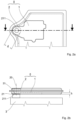
- Fig. 1a and 1b Such a module housing is shown according to the state of the art.
- the two screw sleeves are arranged relative to the heat sink in such a way that an imaginary straight line between them runs across the exposed flat surface of the heat sink.
- the heat sink typically has a contact surface that is sized and shaped to match the free flat surface of the heat sink.
- the screw sleeves each embedded at a distance from the heat sink, are positioned opposite screw bushings when the heat sink is properly seated on the heat sink. These can be located in the support serving as the heat sink or in components firmly attached to the support.
- the contact surfaces on the support, one for the heat sink and the other for the screw sleeves are dimensioned or toleranced in such a way that, when the screws are tightened through the screw sleeves into the support, a pressing force is exerted by the heat sink on the support. This creates bending stresses in the module housing along the imaginary connecting line, which can lead to cracking in brittle plastic.
- the object of the invention is to improve a module housing made of plastic with an embedded heat sink so that it can be attached to a carrier free from bending stresses.
- a module housing made of plastic, in particular of duroplast, with an embedded heat sink and at least one embedded screw-on sleeve, which has a collar with an outwardly exposed screw-on surface and is provided for mounting the module housing on a carrier serving as an external heat sink, in that the heat sink and the at least one screw-on sleeve are connected to one another to form a monolithic body, whereby heat is extracted from the heat sink by heat conduction to the carrier, at least via the screw-on surface.
- a pressure force is transmitted into the carrier via the screw-on surface of the at least one screw-on sleeve, which causes an equally large counterforce.
- This counterforce is absorbed by the monolithic body formed by the heat sink and the at least one screw-on sleeve. Since the heat sink bends at most negligibly as a result of the counterforce, which can have a different effect on the carrier depending on how the monolithic body is applied to the carrier, at most negligible bending stresses are also introduced into the plastic.
- Monolithic means that the body consists of a single, indivisible unit.
- the carrier can be designed so that only the screw-on surface comes into contact with the carrier, even if the heat sink is not set back relative to the screw-on surface.
- Exclusive heat removal by heat conduction via the screw-on surface has the particular advantage that to minimize the flatness tolerance, only the screw-on surface needs to undergo final surface processing.
- the cross-section of a monolithic connection is adapted in its height and/or width to the height of the heat sink and the outer diameter of the screw sleeve.
- the screw-on sleeve is completely connected to the heat sink over a height of the heat sink in the direction of a cylinder axis of the screw-on sleeve, whereby a cross-section of the monolithic connection between the heat sink and the screw-on sleeve in the direction of the height of the heat sink is optimized for heat extraction.
- the screw-on sleeve is connected to the heat sink over a width that corresponds at least to the outer diameter of the screw-on sleeve, whereby a cross-section of the monolithic connection between the heat sink and the screw-on sleeve is optimized for heat extraction in the direction of the width of the heat sink.
- the screwing surface is preferably designed to be largely ring-shaped.
- the screwing surface preferably has an outer diameter that is at least twice as large as the inner diameter of the screwing surface.
- a module housing according to the invention can preferably be used in an electrical assembly.
- the electrical assembly is an inverter and/or a transmission.
- an electrical assembly with a module housing according to the invention is used in a motor vehicle, in particular an electric vehicle.
- a module housing according to the invention in the automotive industry.
- a module housing according to the invention is made of plastic, preferably of duroplast.
- a heat sink 1 and at least one screw-on sleeve 2 are embedded in it.
- heat is extracted from the heat sink 1 directly via a free base area of the heat sink (thermal interface) and the at least one screw-on sleeve 2 only functions as a mechanical interface
- the at least one screw-on sleeve 2 of a module housing according to the invention represents both a mechanical and a thermal interface.
- the at least one screw-on sleeve 2 is connected to the heat sink 1, forming a monolithic body 0.
- the monolithic body has exactly one screw-on sleeve 2, with a collar 21 having an outwardly exposed screw-on surface 211, which comes into contact with a support 3 serving as an external heat sink during assembly of the module housing.
- the screw-on surface 211 is an integral part of a flat base surface that extends over the entire monolithic body 0.
- the module housing is mounted, as shown, on a carrier 3 which has a contact surface 31 facing the module housing which is limited to the dimensions of the screwing surface, heat is extracted by heat conduction, but force is also introduced exclusively via the screwing surface 211.
- the screwing surface is finally manufactured to be highly flat.
- the contact surface 31 on the carrier 3 is dimensioned larger, up to a size equal to the base area of the monolithic body 0 (not shown in the drawings), heat is extracted by heat conduction across the entire base area, which, however, places high demands on the flatness of the base area and the contact surface 31.
- one or two additional screwing sleeves 2 formed in the monolithic body can be provided.
Landscapes
- Physics & Mathematics (AREA)
- Thermal Sciences (AREA)
- Engineering & Computer Science (AREA)
- Microelectronics & Electronic Packaging (AREA)
- Cooling Or The Like Of Electrical Apparatus (AREA)
- Cooling Or The Like Of Semiconductors Or Solid State Devices (AREA)
Claims (7)
- Boîtier de module en matière plastique pourvu d'un dissipateur thermique (1) incorporé et au moins une douille à visser (2) incorporée, qui possède un collet (21) avec une surface de vissage (211) exposée vers l'extérieur et qui est prévue pour le montage du boîtier de module sur un élément porteur (3) servant de puits thermique externe, le dissipateur thermique (1) et l'au moins une douille à visser (2) formant un corps monolithique (0), ce par quoi il se produit une extraction de chaleur du dissipateur thermique (1) par conduction thermique vers l'élément porteur (3) au moins par le biais de la surface de vissage, exactement une douille à visser (2) étant présente et la surface de vissage (211) étant en relief par rapport au dissipateur thermique (1), de sorte que lors du montage du boîtier de module, seule la surface de vissage (211) vient en appui contre l'élément porteur (3), caractérisé, en ce que la douille à visser (2) est entièrement reliée au dissipateur thermique (1) sur la hauteur du dissipateur thermique (h) dans la direction d'un axe de cylindre (20) de la douille à visser, ce par quoi une section transversale de la liaison monolithique entre le dissipateur thermique (1) et la douille à visser (2) dans le sens de la hauteur du dissipateur thermique (h) est optimisée pour l'extraction de chaleur.
- Boîtier de module en matière plastique pourvu d'un dissipateur thermique incorporé selon la revendication précédente, caractérisé en ce que la douille à visser est reliée au dissipateur thermique (1) sur une largeur qui correspond au moins à un diamètre extérieur de la douille à visser (d), ce par quoi une section transversale de la liaison monolithique entre le dissipateur thermique (1) et la douille à visser (2) dans le sens de la largeur du dissipateur thermique (1) est optimisée pour l'extraction de chaleur.
- Boîtier de module en matière plastique pourvu d'un dissipateur thermique incorporé selon l'une des revendications précédentes, caractérisé en ce que la surface de vissage (211) est de forme annulaire.
- Boîtier de module en matière plastique pourvu d'un dissipateur de chaleur encastré selon la revendication 3, caractérisé en ce que la surface de vissage (211) présente un diamètre extérieur qui est au moins deux fois plus grand que le diamètre intérieur de la surface de vissage (211).
- Boîtier de module en matière plastique pourvu d'un dissipateur thermique incorporé selon l'une des revendications précédentes, caractérisé en ce que la matière plastique est un plastique thermodurcissable.
- Sous-ensemble électrique comprenant un boîtier de module selon l'une des revendications précédentes.
- Véhicule automobile équipé d'une commande comprenant un sous-ensemble électrique selon la revendication 6.
Applications Claiming Priority (1)
| Application Number | Priority Date | Filing Date | Title |
|---|---|---|---|
| DE102021208578.4A DE102021208578A1 (de) | 2021-08-06 | 2021-08-06 | Modulgehäuse aus Kunststoff mit eingebettetem Kühlkörper |
Publications (2)
| Publication Number | Publication Date |
|---|---|
| EP4131368A1 EP4131368A1 (fr) | 2023-02-08 |
| EP4131368B1 true EP4131368B1 (fr) | 2025-03-12 |
Family
ID=82742758
Family Applications (1)
| Application Number | Title | Priority Date | Filing Date |
|---|---|---|---|
| EP22186872.2A Active EP4131368B1 (fr) | 2021-08-06 | 2022-07-26 | Boîtier modulaire en matière plastique pourvu de dissipateur thermique incorporé |
Country Status (3)
| Country | Link |
|---|---|
| US (1) | US12004330B2 (fr) |
| EP (1) | EP4131368B1 (fr) |
| DE (1) | DE102021208578A1 (fr) |
Family Cites Families (12)
| Publication number | Priority date | Publication date | Assignee | Title |
|---|---|---|---|---|
| DE19855389C2 (de) * | 1998-12-01 | 2002-10-31 | Siemens Ag | Elektronische Vorrichtung |
| JP4585828B2 (ja) * | 2004-10-06 | 2010-11-24 | 日立オートモティブシステムズ株式会社 | 制御装置およびその製造方法 |
| JP4408444B2 (ja) * | 2007-09-28 | 2010-02-03 | 株式会社日立製作所 | Lcモジュール構造を用いた電子制御装置 |
| US7724526B2 (en) | 2008-10-10 | 2010-05-25 | Delphi Technologies, Inc. | Electronic module with heat sink |
| JP2010245174A (ja) * | 2009-04-02 | 2010-10-28 | Denso Corp | 電子制御ユニット及びその製造方法 |
| JP5570361B2 (ja) * | 2010-09-22 | 2014-08-13 | 三菱電機株式会社 | 防水型電子装置及びその組立方法 |
| JP5907152B2 (ja) * | 2013-11-29 | 2016-04-20 | 株式会社デンソー | 駆動装置 |
| JP6278243B2 (ja) * | 2015-01-07 | 2018-02-14 | 株式会社オートネットワーク技術研究所 | 蓄電ユニット |
| DE102015206480A1 (de) * | 2015-04-10 | 2016-10-13 | Robert Bosch Gmbh | Steuergerät |
| DE102015118452B4 (de) * | 2015-10-29 | 2022-12-15 | Magna Pt B.V. & Co. Kg | Antriebsstrang für ein Kraftfahrzeug und Leiterplattenanordnung dafür |
| DE202017104164U1 (de) | 2017-07-12 | 2017-08-04 | Ekl Ag | Montagesystem und Kühlvorrichtung für COM-Module |
| JP2019065805A (ja) * | 2017-10-03 | 2019-04-25 | アイシン精機株式会社 | 冷却装置 |
-
2021
- 2021-08-06 DE DE102021208578.4A patent/DE102021208578A1/de not_active Ceased
-
2022
- 2022-07-26 EP EP22186872.2A patent/EP4131368B1/fr active Active
- 2022-08-05 US US17/817,827 patent/US12004330B2/en active Active
Also Published As
| Publication number | Publication date |
|---|---|
| DE102021208578A1 (de) | 2023-02-09 |
| EP4131368A1 (fr) | 2023-02-08 |
| US20230040852A1 (en) | 2023-02-09 |
| US12004330B2 (en) | 2024-06-04 |
Similar Documents
| Publication | Publication Date | Title |
|---|---|---|
| DE102005024900B4 (de) | Leistungsmodul | |
| EP1006766B2 (fr) | Dispositif électronique | |
| EP1841302B1 (fr) | Appareil de commande électronique dans des véhicules | |
| EP0708583A1 (fr) | Appareil électrique et sa fabrication | |
| DE4422113C2 (de) | Elektronikmodul | |
| EP1208618A1 (fr) | Appareil de commande et procede de soudage | |
| EP2736310A2 (fr) | Appareil électronique doté d'une liaison de couvercle conductrice d'électricité | |
| EP0682467A2 (fr) | Dispositif de commande à circuit de ventilateur d'automobile | |
| DE102015219851B4 (de) | Steuergerät | |
| DE102017125505A1 (de) | Steckerbuchse für Leiterplatinen | |
| EP4131368B1 (fr) | Boîtier modulaire en matière plastique pourvu de dissipateur thermique incorporé | |
| WO2010076100A1 (fr) | Agencement de circuit électrique et procédé de fabrication d'un agencement de circuit électrique | |
| DE19904279B4 (de) | Halbleitervorrichtung | |
| WO2008083878A1 (fr) | Élément de fixation pour cartes de circuits imprimés | |
| EP3376602A1 (fr) | Module électronique de sécurité | |
| DE102010012331A1 (de) | Schaltungsanordnung mit Abstandshaltern für elektrische Bauteile | |
| EP2514285B1 (fr) | Élément de fermeture pour un boîtier | |
| EP3292592B1 (fr) | Cosse de batterie et son procédé de fabrication | |
| EP1597951B1 (fr) | Appareil electronique a dissipation de chaleur plus sure | |
| DE102012105352A1 (de) | Positionierelement | |
| EP2255430A2 (fr) | Unité moteur-transmission et système modulaire | |
| EP3749073A1 (fr) | Appareil électrique | |
| DE102016208737A1 (de) | Montageadapter und Leistungsmodulsystem | |
| EP1864557B1 (fr) | Procede de production d'un appareil electronique, et appareil electronique | |
| EP1467432A1 (fr) | Adaptateur de contact pour faire un contact à une structure d'antenne pour une voiture |
Legal Events
| Date | Code | Title | Description |
|---|---|---|---|
| PUAI | Public reference made under article 153(3) epc to a published international application that has entered the european phase |
Free format text: ORIGINAL CODE: 0009012 |
|
| STAA | Information on the status of an ep patent application or granted ep patent |
Free format text: STATUS: THE APPLICATION HAS BEEN PUBLISHED |
|
| AK | Designated contracting states |
Kind code of ref document: A1 Designated state(s): AL AT BE BG CH CY CZ DE DK EE ES FI FR GB GR HR HU IE IS IT LI LT LU LV MC MK MT NL NO PL PT RO RS SE SI SK SM TR |
|
| STAA | Information on the status of an ep patent application or granted ep patent |
Free format text: STATUS: REQUEST FOR EXAMINATION WAS MADE |
|
| 17P | Request for examination filed |
Effective date: 20230714 |
|
| RBV | Designated contracting states (corrected) |
Designated state(s): AL AT BE BG CH CY CZ DE DK EE ES FI FR GB GR HR HU IE IS IT LI LT LU LV MC MK MT NL NO PL PT RO RS SE SI SK SM TR |
|
| GRAP | Despatch of communication of intention to grant a patent |
Free format text: ORIGINAL CODE: EPIDOSNIGR1 |
|
| STAA | Information on the status of an ep patent application or granted ep patent |
Free format text: STATUS: GRANT OF PATENT IS INTENDED |
|
| INTG | Intention to grant announced |
Effective date: 20241106 |
|
| RIC1 | Information provided on ipc code assigned before grant |
Ipc: H05K 7/20 20060101ALI20241025BHEP Ipc: H01L 23/40 20060101AFI20241025BHEP |
|
| GRAS | Grant fee paid |
Free format text: ORIGINAL CODE: EPIDOSNIGR3 |
|
| GRAA | (expected) grant |
Free format text: ORIGINAL CODE: 0009210 |
|
| STAA | Information on the status of an ep patent application or granted ep patent |
Free format text: STATUS: THE PATENT HAS BEEN GRANTED |
|
| AK | Designated contracting states |
Kind code of ref document: B1 Designated state(s): AL AT BE BG CH CY CZ DE DK EE ES FI FR GB GR HR HU IE IS IT LI LT LU LV MC MK MT NL NO PL PT RO RS SE SI SK SM TR |
|
| REG | Reference to a national code |
Ref country code: GB Ref legal event code: FG4D Free format text: NOT ENGLISH |
|
| REG | Reference to a national code |
Ref country code: CH Ref legal event code: EP |
|
| REG | Reference to a national code |
Ref country code: DE Ref legal event code: R096 Ref document number: 502022003149 Country of ref document: DE |
|
| REG | Reference to a national code |
Ref country code: IE Ref legal event code: FG4D Free format text: LANGUAGE OF EP DOCUMENT: GERMAN |
|
| PG25 | Lapsed in a contracting state [announced via postgrant information from national office to epo] |
Ref country code: RS Free format text: LAPSE BECAUSE OF FAILURE TO SUBMIT A TRANSLATION OF THE DESCRIPTION OR TO PAY THE FEE WITHIN THE PRESCRIBED TIME-LIMIT Effective date: 20250612 |
|
| PG25 | Lapsed in a contracting state [announced via postgrant information from national office to epo] |
Ref country code: FI Free format text: LAPSE BECAUSE OF FAILURE TO SUBMIT A TRANSLATION OF THE DESCRIPTION OR TO PAY THE FEE WITHIN THE PRESCRIBED TIME-LIMIT Effective date: 20250312 |
|
| PG25 | Lapsed in a contracting state [announced via postgrant information from national office to epo] |
Ref country code: ES Free format text: LAPSE BECAUSE OF FAILURE TO SUBMIT A TRANSLATION OF THE DESCRIPTION OR TO PAY THE FEE WITHIN THE PRESCRIBED TIME-LIMIT Effective date: 20250312 |
|
| REG | Reference to a national code |
Ref country code: LT Ref legal event code: MG9D |
|
| PG25 | Lapsed in a contracting state [announced via postgrant information from national office to epo] |
Ref country code: NO Free format text: LAPSE BECAUSE OF FAILURE TO SUBMIT A TRANSLATION OF THE DESCRIPTION OR TO PAY THE FEE WITHIN THE PRESCRIBED TIME-LIMIT Effective date: 20250612 |
|
| PG25 | Lapsed in a contracting state [announced via postgrant information from national office to epo] |
Ref country code: HR Free format text: LAPSE BECAUSE OF FAILURE TO SUBMIT A TRANSLATION OF THE DESCRIPTION OR TO PAY THE FEE WITHIN THE PRESCRIBED TIME-LIMIT Effective date: 20250312 |
|
| REG | Reference to a national code |
Ref country code: NL Ref legal event code: MP Effective date: 20250312 |
|
| PG25 | Lapsed in a contracting state [announced via postgrant information from national office to epo] |
Ref country code: LV Free format text: LAPSE BECAUSE OF FAILURE TO SUBMIT A TRANSLATION OF THE DESCRIPTION OR TO PAY THE FEE WITHIN THE PRESCRIBED TIME-LIMIT Effective date: 20250312 |
|
| PG25 | Lapsed in a contracting state [announced via postgrant information from national office to epo] |
Ref country code: BG Free format text: LAPSE BECAUSE OF FAILURE TO SUBMIT A TRANSLATION OF THE DESCRIPTION OR TO PAY THE FEE WITHIN THE PRESCRIBED TIME-LIMIT Effective date: 20250312 Ref country code: GR Free format text: LAPSE BECAUSE OF FAILURE TO SUBMIT A TRANSLATION OF THE DESCRIPTION OR TO PAY THE FEE WITHIN THE PRESCRIBED TIME-LIMIT Effective date: 20250613 |
|
| PG25 | Lapsed in a contracting state [announced via postgrant information from national office to epo] |
Ref country code: NL Free format text: LAPSE BECAUSE OF FAILURE TO SUBMIT A TRANSLATION OF THE DESCRIPTION OR TO PAY THE FEE WITHIN THE PRESCRIBED TIME-LIMIT Effective date: 20250312 |
|
| PG25 | Lapsed in a contracting state [announced via postgrant information from national office to epo] |
Ref country code: SE Free format text: LAPSE BECAUSE OF FAILURE TO SUBMIT A TRANSLATION OF THE DESCRIPTION OR TO PAY THE FEE WITHIN THE PRESCRIBED TIME-LIMIT Effective date: 20250312 |
|
| PG25 | Lapsed in a contracting state [announced via postgrant information from national office to epo] |
Ref country code: SM Free format text: LAPSE BECAUSE OF FAILURE TO SUBMIT A TRANSLATION OF THE DESCRIPTION OR TO PAY THE FEE WITHIN THE PRESCRIBED TIME-LIMIT Effective date: 20250312 |
|
| PG25 | Lapsed in a contracting state [announced via postgrant information from national office to epo] |
Ref country code: PT Free format text: LAPSE BECAUSE OF FAILURE TO SUBMIT A TRANSLATION OF THE DESCRIPTION OR TO PAY THE FEE WITHIN THE PRESCRIBED TIME-LIMIT Effective date: 20250714 |
|
| PGFP | Annual fee paid to national office [announced via postgrant information from national office to epo] |
Ref country code: DE Payment date: 20250604 Year of fee payment: 4 |
|
| PG25 | Lapsed in a contracting state [announced via postgrant information from national office to epo] |
Ref country code: PL Free format text: LAPSE BECAUSE OF FAILURE TO SUBMIT A TRANSLATION OF THE DESCRIPTION OR TO PAY THE FEE WITHIN THE PRESCRIBED TIME-LIMIT Effective date: 20250312 Ref country code: IT Free format text: LAPSE BECAUSE OF FAILURE TO SUBMIT A TRANSLATION OF THE DESCRIPTION OR TO PAY THE FEE WITHIN THE PRESCRIBED TIME-LIMIT Effective date: 20250312 |
|
| PGFP | Annual fee paid to national office [announced via postgrant information from national office to epo] |
Ref country code: AT Payment date: 20251020 Year of fee payment: 4 |
|
| PG25 | Lapsed in a contracting state [announced via postgrant information from national office to epo] |
Ref country code: CZ Free format text: LAPSE BECAUSE OF FAILURE TO SUBMIT A TRANSLATION OF THE DESCRIPTION OR TO PAY THE FEE WITHIN THE PRESCRIBED TIME-LIMIT Effective date: 20250312 Ref country code: EE Free format text: LAPSE BECAUSE OF FAILURE TO SUBMIT A TRANSLATION OF THE DESCRIPTION OR TO PAY THE FEE WITHIN THE PRESCRIBED TIME-LIMIT Effective date: 20250312 |
|
| PG25 | Lapsed in a contracting state [announced via postgrant information from national office to epo] |
Ref country code: RO Free format text: LAPSE BECAUSE OF FAILURE TO SUBMIT A TRANSLATION OF THE DESCRIPTION OR TO PAY THE FEE WITHIN THE PRESCRIBED TIME-LIMIT Effective date: 20250312 |
|
| PG25 | Lapsed in a contracting state [announced via postgrant information from national office to epo] |
Ref country code: SK Free format text: LAPSE BECAUSE OF FAILURE TO SUBMIT A TRANSLATION OF THE DESCRIPTION OR TO PAY THE FEE WITHIN THE PRESCRIBED TIME-LIMIT Effective date: 20250312 |
|
| PG25 | Lapsed in a contracting state [announced via postgrant information from national office to epo] |
Ref country code: IS Free format text: LAPSE BECAUSE OF FAILURE TO SUBMIT A TRANSLATION OF THE DESCRIPTION OR TO PAY THE FEE WITHIN THE PRESCRIBED TIME-LIMIT Effective date: 20250712 |
|
| REG | Reference to a national code |
Ref country code: DE Ref legal event code: R079 Ref document number: 502022003149 Country of ref document: DE Free format text: PREVIOUS MAIN CLASS: H01L0023400000 Ipc: H10W0040600000 |
|
| REG | Reference to a national code |
Ref country code: DE Ref legal event code: R097 Ref document number: 502022003149 Country of ref document: DE |
|
| PG25 | Lapsed in a contracting state [announced via postgrant information from national office to epo] |
Ref country code: DK Free format text: LAPSE BECAUSE OF FAILURE TO SUBMIT A TRANSLATION OF THE DESCRIPTION OR TO PAY THE FEE WITHIN THE PRESCRIBED TIME-LIMIT Effective date: 20250312 |
|
| PLBE | No opposition filed within time limit |
Free format text: ORIGINAL CODE: 0009261 |
|
| STAA | Information on the status of an ep patent application or granted ep patent |
Free format text: STATUS: NO OPPOSITION FILED WITHIN TIME LIMIT |
|
| REG | Reference to a national code |
Ref country code: CH Ref legal event code: L10 Free format text: ST27 STATUS EVENT CODE: U-0-0-L10-L00 (AS PROVIDED BY THE NATIONAL OFFICE) Effective date: 20260121 |
|
| 26N | No opposition filed |
Effective date: 20251215 |
|
| REG | Reference to a national code |
Ref country code: CH Ref legal event code: H13 Free format text: ST27 STATUS EVENT CODE: U-0-0-H10-H13 (AS PROVIDED BY THE NATIONAL OFFICE) Effective date: 20260224 |
|
| PG25 | Lapsed in a contracting state [announced via postgrant information from national office to epo] |
Ref country code: LU Free format text: LAPSE BECAUSE OF NON-PAYMENT OF DUE FEES Effective date: 20250726 |
|
| REG | Reference to a national code |
Ref country code: BE Ref legal event code: MM Effective date: 20250731 |
|
| PG25 | Lapsed in a contracting state [announced via postgrant information from national office to epo] |
Ref country code: BE Free format text: LAPSE BECAUSE OF NON-PAYMENT OF DUE FEES Effective date: 20250731 |
|
| PG25 | Lapsed in a contracting state [announced via postgrant information from national office to epo] |
Ref country code: FR Free format text: LAPSE BECAUSE OF NON-PAYMENT OF DUE FEES Effective date: 20250731 |
|
| PG25 | Lapsed in a contracting state [announced via postgrant information from national office to epo] |
Ref country code: CH Free format text: LAPSE BECAUSE OF NON-PAYMENT OF DUE FEES Effective date: 20250731 |