EP4131499A1 - Negativelektrodenmaterial, negativelektrodenfolie, elektrochemische vorrichtung und elektronische vorrichtung - Google Patents
Negativelektrodenmaterial, negativelektrodenfolie, elektrochemische vorrichtung und elektronische vorrichtung Download PDFInfo
- Publication number
- EP4131499A1 EP4131499A1 EP20928837.2A EP20928837A EP4131499A1 EP 4131499 A1 EP4131499 A1 EP 4131499A1 EP 20928837 A EP20928837 A EP 20928837A EP 4131499 A1 EP4131499 A1 EP 4131499A1
- Authority
- EP
- European Patent Office
- Prior art keywords
- group
- negative electrode
- silicon
- carbon nanotubes
- based material
- Prior art date
- Legal status (The legal status is an assumption and is not a legal conclusion. Google has not performed a legal analysis and makes no representation as to the accuracy of the status listed.)
- Pending
Links
Images


Classifications
-
- H—ELECTRICITY
- H01—ELECTRIC ELEMENTS
- H01M—PROCESSES OR MEANS, e.g. BATTERIES, FOR THE DIRECT CONVERSION OF CHEMICAL ENERGY INTO ELECTRICAL ENERGY
- H01M4/00—Electrodes
- H01M4/02—Electrodes composed of, or comprising, active material
- H01M4/36—Selection of substances as active materials, active masses, active liquids
- H01M4/362—Composites
- H01M4/364—Composites as mixtures
-
- H—ELECTRICITY
- H01—ELECTRIC ELEMENTS
- H01M—PROCESSES OR MEANS, e.g. BATTERIES, FOR THE DIRECT CONVERSION OF CHEMICAL ENERGY INTO ELECTRICAL ENERGY
- H01M4/00—Electrodes
- H01M4/02—Electrodes composed of, or comprising, active material
- H01M4/04—Processes of manufacture in general
- H01M4/0402—Methods of deposition of the material
- H01M4/0404—Methods of deposition of the material by coating on electrode collectors
-
- H—ELECTRICITY
- H01—ELECTRIC ELEMENTS
- H01M—PROCESSES OR MEANS, e.g. BATTERIES, FOR THE DIRECT CONVERSION OF CHEMICAL ENERGY INTO ELECTRICAL ENERGY
- H01M10/00—Secondary cells; Manufacture thereof
- H01M10/05—Accumulators with non-aqueous electrolyte
- H01M10/052—Li-accumulators
- H01M10/0525—Rocking-chair batteries, i.e. batteries with lithium insertion or intercalation in both electrodes; Lithium-ion batteries
-
- H—ELECTRICITY
- H01—ELECTRIC ELEMENTS
- H01M—PROCESSES OR MEANS, e.g. BATTERIES, FOR THE DIRECT CONVERSION OF CHEMICAL ENERGY INTO ELECTRICAL ENERGY
- H01M4/00—Electrodes
- H01M4/02—Electrodes composed of, or comprising, active material
- H01M4/13—Electrodes for accumulators with non-aqueous electrolyte, e.g. for lithium-accumulators; Processes of manufacture thereof
- H01M4/134—Electrodes based on metals, Si or alloys
-
- H—ELECTRICITY
- H01—ELECTRIC ELEMENTS
- H01M—PROCESSES OR MEANS, e.g. BATTERIES, FOR THE DIRECT CONVERSION OF CHEMICAL ENERGY INTO ELECTRICAL ENERGY
- H01M4/00—Electrodes
- H01M4/02—Electrodes composed of, or comprising, active material
- H01M4/13—Electrodes for accumulators with non-aqueous electrolyte, e.g. for lithium-accumulators; Processes of manufacture thereof
- H01M4/139—Processes of manufacture
- H01M4/1395—Processes of manufacture of electrodes based on metals, Si or alloys
-
- H—ELECTRICITY
- H01—ELECTRIC ELEMENTS
- H01M—PROCESSES OR MEANS, e.g. BATTERIES, FOR THE DIRECT CONVERSION OF CHEMICAL ENERGY INTO ELECTRICAL ENERGY
- H01M4/00—Electrodes
- H01M4/02—Electrodes composed of, or comprising, active material
- H01M4/36—Selection of substances as active materials, active masses, active liquids
- H01M4/38—Selection of substances as active materials, active masses, active liquids of elements or alloys
- H01M4/386—Silicon or alloys based on silicon
-
- H—ELECTRICITY
- H01—ELECTRIC ELEMENTS
- H01M—PROCESSES OR MEANS, e.g. BATTERIES, FOR THE DIRECT CONVERSION OF CHEMICAL ENERGY INTO ELECTRICAL ENERGY
- H01M4/00—Electrodes
- H01M4/02—Electrodes composed of, or comprising, active material
- H01M4/36—Selection of substances as active materials, active masses, active liquids
- H01M4/58—Selection of substances as active materials, active masses, active liquids of inorganic compounds other than oxides or hydroxides, e.g. sulfides, selenides, tellurides, halogenides or LiCoFy; of polyanionic structures, e.g. phosphates, silicates or borates
- H01M4/583—Carbonaceous material, e.g. graphite-intercalation compounds or CFx
-
- H—ELECTRICITY
- H01—ELECTRIC ELEMENTS
- H01M—PROCESSES OR MEANS, e.g. BATTERIES, FOR THE DIRECT CONVERSION OF CHEMICAL ENERGY INTO ELECTRICAL ENERGY
- H01M4/00—Electrodes
- H01M4/02—Electrodes composed of, or comprising, active material
- H01M4/62—Selection of inactive substances as ingredients for active masses, e.g. binders, fillers
- H01M4/621—Binders
- H01M4/622—Binders being polymers
-
- H—ELECTRICITY
- H01—ELECTRIC ELEMENTS
- H01M—PROCESSES OR MEANS, e.g. BATTERIES, FOR THE DIRECT CONVERSION OF CHEMICAL ENERGY INTO ELECTRICAL ENERGY
- H01M4/00—Electrodes
- H01M4/02—Electrodes composed of, or comprising, active material
- H01M4/62—Selection of inactive substances as ingredients for active masses, e.g. binders, fillers
- H01M4/624—Electric conductive fillers
- H01M4/625—Carbon or graphite
-
- H—ELECTRICITY
- H01—ELECTRIC ELEMENTS
- H01M—PROCESSES OR MEANS, e.g. BATTERIES, FOR THE DIRECT CONVERSION OF CHEMICAL ENERGY INTO ELECTRICAL ENERGY
- H01M50/00—Constructional details or processes of manufacture of the non-active parts of electrochemical cells other than fuel cells, e.g. hybrid cells
- H01M50/40—Separators; Membranes; Diaphragms; Spacing elements inside cells
- H01M50/46—Separators, membranes or diaphragms characterised by their combination with electrodes
-
- H—ELECTRICITY
- H01—ELECTRIC ELEMENTS
- H01M—PROCESSES OR MEANS, e.g. BATTERIES, FOR THE DIRECT CONVERSION OF CHEMICAL ENERGY INTO ELECTRICAL ENERGY
- H01M4/00—Electrodes
- H01M4/02—Electrodes composed of, or comprising, active material
- H01M2004/026—Electrodes composed of, or comprising, active material characterised by the polarity
- H01M2004/027—Negative electrodes
-
- H—ELECTRICITY
- H01—ELECTRIC ELEMENTS
- H01M—PROCESSES OR MEANS, e.g. BATTERIES, FOR THE DIRECT CONVERSION OF CHEMICAL ENERGY INTO ELECTRICAL ENERGY
- H01M4/00—Electrodes
- H01M4/02—Electrodes composed of, or comprising, active material
- H01M2004/026—Electrodes composed of, or comprising, active material characterised by the polarity
- H01M2004/028—Positive electrodes
-
- Y—GENERAL TAGGING OF NEW TECHNOLOGICAL DEVELOPMENTS; GENERAL TAGGING OF CROSS-SECTIONAL TECHNOLOGIES SPANNING OVER SEVERAL SECTIONS OF THE IPC; TECHNICAL SUBJECTS COVERED BY FORMER USPC CROSS-REFERENCE ART COLLECTIONS [XRACs] AND DIGESTS
- Y02—TECHNOLOGIES OR APPLICATIONS FOR MITIGATION OR ADAPTATION AGAINST CLIMATE CHANGE
- Y02E—REDUCTION OF GREENHOUSE GAS [GHG] EMISSIONS, RELATED TO ENERGY GENERATION, TRANSMISSION OR DISTRIBUTION
- Y02E60/00—Enabling technologies; Technologies with a potential or indirect contribution to GHG emissions mitigation
- Y02E60/10—Energy storage using batteries
Definitions
- This application relates to the field of electronic technologies, and in particular, to a negative electrode material, a negative electrode plate, an electrochemical apparatus, and an electronic apparatus.
- silicon-based materials are promising negative electrode materials for next-generation electrochemical apparatuses (such as lithium-ion batteries).
- next-generation electrochemical apparatuses such as lithium-ion batteries.
- the silicon-based material experiences a volume swelling of about 300%, and an unstable solid electrolyte interface film (SEI, solid electrolyte interface) is formed on its surface, which all affect performance of the electrochemical apparatuses.
- SEI solid electrolyte interface film
- carbon nanotubes can be used to coat the silicon-based materials.
- an existing carbon nanotube coating solution is unsatisfactory.
- this application uses a polymer containing two groups to improve bonding between a silicon-based material and carbon nanotubes.
- This application provides a negative electrode material, including a composite of a silicon-based material, a polymer, and carbon nanotubes, where the polymer contains a first group and a second group, the first group is chemically bonded to the carbon nanotubes, and the second group is chemically bonded to the silicon-based material.
- the carbon nanotubes are present on a surface of the silicon-based material.
- the first group includes at least one of epoxy group, phenolic hydroxyl group, phenylamino group, phenyl group, naphthyl group, anthranyl group, phenanthryl group, phenyl ether group, pyrrole, pyridine, or furan.
- the second group includes at least one of carboxyl group, hydroxyl group, phenolic hydroxyl group, aldehyde group, acylamino group, acyl halide group, ester group, carbonyl group, or halogenated alkyl group.
- a mass percentage of the polymer in the composite is 0.5%-10%.
- a mass percentage of the carbon nanotubes in the composite is 0.5%-10%.
- a mass ratio of the silicon-based material to the polymer to the carbon nanotubes in the composite is 85-96.5:0.5-10:0.5-10.
- a highest intensity value of the silicon-based material is I 1 when 2 ⁇ is in the range of 20.5° to 21.5°, and the highest intensity value is I 2 when 2 ⁇ is in the range of 28.0° to 29.0°, where 0 ⁇ I 2 /I 1 ⁇ 3.
- the negative electrode material is further doped with at least one of element lithium, magnesium, titanium, or aluminum.
- This application further provides a negative electrode plate, including a current collector and an active substance layer provided on the current collector, where the active substance layer includes the negative electrode material in any one of the foregoing embodiments.
- This application further provides an electrochemical apparatus, including a positive electrode plate, a negative electrode plate, and a separator disposed between the positive electrode plate and the negative electrode plate, where the negative electrode plate is the foregoing negative electrode plate.
- This application further provides an electronic apparatus, including the foregoing electrochemical apparatus.
- both carbon nanotubes and a polymer containing two groups are applied to surfaces of particles of a silicon-based material.
- the two groups of the polymer are chemically bonded to the silicon-based material and the carbon nanotubes respectively, so that bonding force between the silicon-based material and the carbon nanotubes is enhanced and a uniform carbon nanotube coating layer is formed.
- This can significantly improve conductive performance of the silicon-based material, thereby improving cycling performance and rate performance of an electrochemical apparatus.
- a porous silicon-based material may be used.
- polymer coating, oxide coating, carbon material coating, or the like may be used, among which polymer coating has poorer conductive performance and larger impedance.
- Carbon material coating is an important means. Due to good mechanical performance (with a tensile intensity of up to 200 GPa, 100 times that of steel; and an elastic modulus of up to 1 TPa, about 5 times that of steel) and good conductive performance (with a conductivity that can generally reach 10,000 times that of steel), carbon nanotubes can be used as an excellent coating material for the silicon-based material.
- Carbon nanotube coating as a widely used technology in recent years, not only alleviates volume swelling of the silicon-based material, but also significantly improves conductive performance of the silicon-based material.
- a surface bonding force between highly conductive carbon nanotubes and the silicon-based material is weak in the absence of direct bonding between them.
- agglomeration of the carbon nanotubes leads to poor dispersibility, it is difficult to form a uniform carbon nanotube coating layer on a surface of the silicon-based material. Therefore, a conductive network structure, rather than uniform and effective coating, can be formed by adding carbon nanotubes into a silicon-based material.
- carboxymethyl cellulose is used to disperse carbon nanotubes on a surface of a silicon-based material.
- bonding force between carboxymethyl cellulose and carbon nanotubes is weak in the absence of direct chemical bonding between them.
- both carbon nanotubes and a polymer containing two groups are applied to surfaces of particles of a silicon-based material.
- the two groups of the polymer are chemically bonded to the silicon-based material and the carbon nanotubes respectively, so that bonding force between the silicon-based material and the carbon nanotubes is enhanced and a uniform carbon nanotube coating layer is formed.
- This can significantly improve conductive performance of a silicon-based negative electrode material, thereby improving cycling performance and rate performance of an electrochemical apparatus.
- the negative electrode material includes a composite of a silicon-based material 1, a polymer 2, and carbon nanotubes 3.
- the polymer 2 contains a first group and a second group, the first group is chemically bonded to the carbon nanotubes 3, and the second group is chemically bonded to the silicon-based material 1.
- the chemical bonding between the first group and the carbon nanotubes 3 enhances bonding force between the polymer 2 and the carbon nanotubes 3, so that bonding force between the silicon-based material and the carbon nanotubes 3 is enhanced and a uniform carbon nanotube coating layer is formed. This improves conductive performance of the silicon-based material, thereby improving cycling performance and rate performance of an electrochemical apparatus.
- the silicon-based material includes at least one of silicon nanoparticles, silicon monoxide, or silicon-carbon composite particles. In some embodiments, the silicon-based material includes at least one of silicon, silicon oxygen, silicon carbon, or silicon alloy. In some embodiments, the silicon-based material may contain element lithium, magnesium, titanium, aluminum, or the like. These doping metal elements can improve conductive performance of the negative electrode material, first-cycle coulombic efficiency of a battery, and cycling performance and DCR (Directive Current Resistance, directive current resistance) of an electrochemical apparatus. In some embodiments, an average particle size of silicon-based particles is 500 nm-30 ⁇ m, where nano-silicon crystal grains are less than 100 nm in size.
- an average particle size of the silicon-based material is excessively small, the silicon-based material is prone to agglomeration, and a large specific surface area consumes more electrolytes to form an SEI film.
- An excessively large average particle size of the silicon-based material does not help suppress volume swelling of the silicon-based material, but easily deteriorates conductive performance of an active substance layer.
- the excessively large average particle size of the silicon-based material reduces strength of a negative electrode plate.
- a particle size of Si is less than 100 nm.
- the polymer 2 bridges the silicon-based material 1 and the carbon nanotubes 3.
- the carbon nanotubes 3 are present on a surface of the silicon-based material 1.
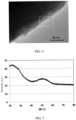
- FIG. 4 is a TEM image of a silicon-based material bridged to carbon nanotubes through a polymer, where the carbon nanotubes are shown in a dashed-line box.
- the silicon-based material 1 is silicon-based particles, and the carbon nanotubes 3 are bridged to the silicon-based material 1 through the polymer 2 and coat the surface of the silicon-based material 1.
- the polymer 2 enhances bonding force between the silicon-based material 1 and the carbon nanotubes 3, and improves uniform dispersibility of the carbon nanotubes 3 on the surface of the silicon-based material 1, preventing the carbon nanotubes 3 from agglomerating on the surface of the silicon-based material 1.
- the carbon nanotubes may include at least one of Li, Na, K, or other alkali metal ions.
- the carbon nanotubes include single-walled carbon nanotubes, multi-walled carbon nanotubes, or a combination thereof.
- a diameter of the carbon nanotube is 1 nm-30 nm, with a length-diameter ratio of 50 to 30000.
- the first group includes at least one of epoxy group, phenolic hydroxyl group, phenylamino group, phenyl group, naphthyl group, anthranyl group, phenanthryl group, phenyl ether group, pyrrole, pyridine, or furan.
- the second group includes at least one of carboxyl group, hydroxyl group, phenolic hydroxyl group, aldehyde group, acylamino group, acyl halide group, ester group, carbonyl group, or halogenated alkyl group.
- the first group facilitates chemical bonding between the polymer and the carbon nanotubes
- the second group facilitates chemical bonding between the polymer and the silicon-based material.
- a mass percentage of the polymer in the composite is 0.5%-10%.
- An excessively low percentage of the polymer cannot effectively enhance bonding between particles of the silicon-based material and the carbon nanotubes, such that electronic conductivity of the negative electrode material and the cycling performance and directive current resistance (DCR) of the electrochemical apparatus cannot be effectively improved.
- An excessively high percentage of the polymer can effectively enhance the bonding between the particles of the silicon-based material and the carbon nanotubes through the two groups of the polymer, but reduces the electronic conductivity of the negative electrode material due to poor conductive performance of the polymer, further affecting the cycling performance and directive current resistance (DCR) of the electrochemical apparatus.
- thickness of a polymer layer is 5 nm-200 nm.
- a mass percentage of the carbon nanotubes in the composite is 0.5%-10%.
- a percentage of the carbon nanotubes is excessively low, the conductive performance of the silicon-based material cannot be effectively improved.
- the percentage of the carbon nanotubes is excessively high, a carbon nanotube coating layer is too thick, which is not conducive to migration of lithium ions, thereby deteriorating the cycling performance of the electrochemical apparatus.
- a mass ratio of the silicon-based material to the polymer to the carbon nanotubes in the composite is 85-96.5:0.5-10:0.5-10.
- An appropriate ratio of materials can effectively overcome the problems of poor conductive performance and large volume swelling of the silicon-based material while exerting the advantage of high specific capacity of the silicon-based material, thereby improving cycling performance and rate performance of a formed electrochemical apparatus.
- a highest intensity value of the silicon-based material is I 1 when 2 ⁇ is in the range of 20.5° to 21.5°, and the highest intensity value is I 2 when 2 ⁇ is in the range of 28.0° to 29.0°, where 0 ⁇ I 2 /I 1 ⁇ 3.
- a value of I 2 /I 1 reflects to what extent the silicon-based material is affected by disproportionation.
- a larger value of I 2 /I 1 means larger nano silicon-based crystal grains generated by SiO disproportionation generated in the silicon-based material, which leads to sharply increased stress on some regions during lithiation, thereby causing structural damage to the silicon-based material during cycling.
- the negative electrode material is further doped with at least one of element lithium, magnesium, titanium, or aluminum.
- the negative electrode material being doped with metal elements can improve the conductive performance of the negative electrode material, the first-cycle coulombic efficiency of the battery, and the cycling performance and DCR of the electrochemical apparatus.
- a specific surface area of the negative electrode material is 1 m 2 /g-50 m 2 /g.
- the negative electrode material may be prepared by using the following methods: 0.5 g-15 g of carbon nanotube (CNT) powder is added into a solvent containing 0.5 g-20 g polymer, and the mixture is dispersed for 1 h-24 h to obtain a CNT slurry; 100 g of silicon-based material powder is added into the CNT slurry, and the mixture is stirred at a rotation speed of 300 r/min to 2500 r/min and dispersed for 2 h-4 h to obtain a mixed slurry; the mixed slurry is dried, and the solvent in the mixed slurry is removed to obtain a composite; and the composite is mechanically crushed and sieved with a 400-mesh sieve to obtain a negative electrode material, that is, a silicon-based material coated with CNT and a polymer.
- CNT carbon nanotube
- the solvent in the foregoing preparation process may be at least one of water, ethanol, methanol, n-hexane, N,N-dimethylformamide, pyrrolidone, acetone, toluene, isopropanol, or n-propyl alcohol.
- drying may be rotary evaporation, spray drying, filtration, freeze drying, or the like.
- the negative electrode plate includes a current collector 4 and an active substance layer 5.
- the active substance layer 5 is provided on the current collector 4. It should be understood that, although the active substance layer 5 is provided on one side of the current collector 4 in FIG. 2 , this is only an example, and the active substance layer 5 may be provided on two sides of the current collector 4.
- the current collector of the negative electrode plate may include at least one of copper foil, aluminum foil, nickel foil, or a carbon-based current collector.
- the active substance layer 5 includes the foregoing negative electrode material.
- the active substance layer further includes a carbon material, a conductive agent, and a binder.
- the carbon material includes graphite, graphene, or the like.
- the binder may include at least one of carboxymethyl cellulose (CMC), polyacrylic acid, polyvinylpyrrolidone, polyaniline, polyimide, polyamideimide, polysiloxane, polystyrene-butadiene rubber, epoxy resin, polyester resin, polyurethane resin, or polyfluorene.
- a mass percentage of the binder in the active substance layer is 0.5%-10%.
- the conductive agent includes at least one of single-walled carbon nanotubes, multi-walled carbon nanotubes, vapor grown carbon fiber, conductive carbon black, acetylene black, Ketjen black, conductive graphite, or graphene. In some embodiments, a mass percentage of the conductive agent in the active substance layer is 0.1%-5%.
- the electrochemical apparatus includes a positive electrode plate 10, a negative electrode plate 12, and a separator 11 disposed between the positive electrode plate 10 and the negative electrode plate 12.
- the positive electrode plate 10 may include a positive electrode current collector and a positive electrode active substance layer applied on the positive electrode current collector.
- the positive electrode active substance layer may be applied on only part of the positive electrode current collector.
- the positive electrode active substance layer may include a positive electrode active substance, a conductive agent, and a binder.
- the positive electrode current collector may be Al foil, or may be another positive electrode current collector commonly used in the art.
- the conductive agent in the positive electrode plate may include at least one of conductive carbon black, lamellar graphite, graphene, or carbon nanotubes.
- the binder in the positive electrode plate may include at least one of polyvinylidene fluoride, vinylidene fluoridehexafluoropropylene copolymer, styrene-acrylate copolymer, styrene-butadiene copolymer, polyamide, polyacrylonitrile, polyacrylate ester, polyacrylic acid, polyacrylate salt, sodium carboxymethylcellulose, polyvinyl acetate, polyvinylpyrrolidone, polyvinyl ether, polymethyl methacrylate, polytetrafluoroethylene, or polyhexafluoropropylene.
- the positive electrode active substance includes but is not limited to at least one of lithium cobaltate, lithium nickelate, lithium manganate, lithium nickel manganate, lithium nickel cobaltate, lithium iron phosphate, lithium nickel cobalt aluminate, or lithium nickel cobalt manganate.
- the foregoing positive electrode active substance may be doped or coated.
- the separator 11 includes at least one of polyethylene, polypropylene, polyvinylidene fluoride, polyethylene terephthalate, polyimide, or aramid.
- polyethylene is selected from at least one of high-density polyethylene, low-density polyethylene, or ultra-high molecular weight polyethylene.
- polyethylene and polypropylene can well prevent short circuit, and can improve stability of a battery through a shutdown effect.
- a surface of the separator may further include a porous layer.
- the porous layer is disposed on at least one surface of the separator and includes inorganic particles and a binder, where the inorganic particles are selected from at least one of aluminum oxide (Al 2 O 3 ), silicon dioxide (SiO 2 ), magnesium oxide (MgO), titanium oxide (TiO 2 ), hafnium dioxide (HfO 2 ), stannic oxide (SnO 2 ), cerium dioxide (CeO 2 ), nickel oxide (NiO), zinc oxide (ZnO), calcium oxide (CaO), zirconium dioxide (ZrO 2 ), yttrium oxide (Y 2 O 3 ), silicon carbide (SiC), boehmite, aluminum hydroxide, magnesium hydroxide, calcium hydroxide, or barium sulfate.
- the binder is selected from at least one of polyvinylidene fluoride, vinylidene fluoridehexafluoropropylene copolymer, polyamide, polyacrylonitrile, polyacrylate ester, polyacrylic acid, polyacrylate salt, sodium carboxymethylcellulose, polyvinylpyrrolidone, polyvinyl ether, polymethyl methacrylate, polytetrafluoroethylene, or polyhexafluoropropylene.
- the porous layer on the surface of the separator can improve heat resistance, oxidation resistance, and electrolyte infiltration performance of the separator, and enhance adhesion between the separator and the electrode plates.
- the negative electrode plate 12 may be the negative electrode plate described above.
- an electrode assembly of the electrochemical apparatus is a wound electrode assembly or a stacked electrode assembly.
- the electrochemical apparatus includes a lithium-ion battery, but this applicant is not limited thereto.
- the electrochemical apparatus may further include an electrolyte.
- the electrolyte includes at least two of dimethyl carbonate (DMC), ethyl methyl carbonate (EMC), diethyl carbonate (DEC), ethylene carbonate (EC), propylene carbonate (PC), or propyl propionate (PP).
- the electrolyte may further additionally include at least one of vinylene carbonate (VC), fluoroethylene carbonate (FEC), or dinitrile compound serving as an electrolyte additive.
- a lithium-ion battery is used as an example.
- a positive electrode plate, a separator, and a negative electrode plate are wound or stacked in sequence to form an electrode assembly, and then the electrode assembly is placed into, for example, an aluminum-plastic film, for packaging, followed by injection of an electrolyte, formation, and packaging, so that the lithium-ion battery is prepared. Then, performance and cycling tests are performed on the prepared lithium-ion battery.
- an embodiment of this application further provides an electronic apparatus including the foregoing electrode assembly or an electronic apparatus including the foregoing electrochemical apparatus.
- the electronic apparatus in this application is not particularly limited, and may be any known electronic apparatus used in the prior art.
- the electronic apparatus may include but is not limited to a notebook computer, a pen-input computer, a mobile computer, an electronic book player, a portable telephone, a portable fax machine, a portable copier, a portable printer, a stereo headset, a video recorder, a liquid crystal television, a portable cleaner, a portable CD player, a mini-disc, a transceiver, an electronic notepad, a calculator, a memory card, a portable recorder, a radio, a standby power source, a motor, an automobile, a motorcycle, a power-assisted bicycle, a bicycle, a lighting appliance, a toy, a game console, a clock, an electric tool, a flash lamp, a camera, a large household battery, and
- Lithium-ion batteries are used as examples.
- Preparation of negative electrode material 5 g of carbon nanotube powder was added into a solvent containing 3 g sodium anthranilate (containing carboxyl group and phenylamino group), and the mixture was dispersed for 10 h to obtain a carbon nanotube slurry; 92 g of SiO particles (with a value of I 2 /I 1 being 0.38) was added into the carbon nanotube slurry, and the mixture was stirred at a rotation speed of 2000 r/min and dispersed for 4 h; the mixed slurry was dried, and the solvent in the mixed slurry was removed to obtain a composite; and the composite was mechanically crushed and sieved with a 400-mesh sieve to obtain a negative electrode material coated with carbon nanotubes and a polymer.
- Preparation of negative electrode plate copper foil with a thickness of 10 ⁇ m was used as a current collector; the foregoing silicon-based material and graphite were used as an active material, where a mass percentage of the silicon-based material in an active material layer was 10%; polyacrylic acid was used as a binder; and the active material, conductive carbon black, and binder were mixed at 95:1.2:3.8 and dispersed in water to form a slurry, and the slurry was stirred and then applied onto the copper foil, followed by drying, cold pressing, and slitting to obtain a negative electrode plate.
- positive electrode plate a positive electrode active substance LiCoO 2 , conductive carbon black, and a binder polyvinylidene fluoride (PVDF) were fully stirred and uniformly mixed in an N-methylpyrrolidone solvent system at a mass ratio of 96.7:1.7:1.6, and then the mixture was applied onto an aluminum foil, followed by drying and cold pressing to obtain a positive electrode plate.
- PVDF polyvinylidene fluoride
- Preparation of battery with a polyethylene porous polymer thin film as a separator, the positive electrode plate, the separator, and the negative electrode plate were stacked in sequence, so that the separator was placed between the positive electrode plate and negative electrode plate for isolation, and the stack was wound to obtain an electrode assembly.
- the electrode assembly was placed into an outer package aluminum-plastic film, and an electrolyte containing ethylene carbonate (EC) and propylene carbonate (PC) was injected, followed by processes such as packaging, formation, degassing, and trimming to obtain a lithium-ion battery.
- EC ethylene carbonate
- PC propylene carbonate
- Examples 2 to 22 and Comparative Examples 1 to 3 except for the preparation of the negative electrode materials in the negative electrode plates, the preparation of the positive electrode plates and lithium-ion batteries was the same as that in Example 1. The following describes only differences in the preparation of the negative electrode materials respectively.
- the types of the polymers were changed to epoxy resin (containing hydroxyl group and epoxy group), lithium carboxymethyl cellulose (containing only carboxyl group), polyethylene glycol (containing only hydroxyl group), polyaniline (containing only phenylamino group), polysiloxane (containing only epoxy group), and polyethylene (containing no group A or group B) respectively.
- the negative electrode material, conductive carbon black, and a binder polyacrylic acid (PAA) were added into deionized water at a mass ratio of 80:10:10, and stirred to form a slurry.
- the slurry was applied with a scraper to form a 100 ⁇ m thick coating layer.
- the coating layer was dried in a vacuum drying oven for 12 hours at 85°C, and then cut into a circular plate with a diameter of 1 cm in a dry environment by using a punching machine.
- a lithium metal plate was used as a counter electrode in a glove box, a Ceglard composite film was selected as a separator, and an electrolyte was added, to assemble a button battery.
- a LAND (LAND) battery tester was used to conduct charge and discharge tests on the batteries to test their charge and discharge performance.
- a four-wire and two-terminal method was used. Voltages and flowing current at two terminals of a to-be-tested resistor were measured to determine constant resistance, and conductivity was calculated with reference to a height and a bottom area of the to-be-tested resistor.
- a given amount of powder was added into a test mold and laid flat through slight vibration, and then a spacer on the mold was placed on a sample; after the sample was loaded, the mold was placed on a working platform of an electronic pressure testing machine, and pressure was increased to 500 kg (159 MPa) at a rate of 5 mm/min, held for 60s and then reduced to 0; and when a constant pressure on the sample reached 5000 ⁇ 2 kg (about 15s-25s after the pressure was increased to 5000 kg), the pressure on the sample was recorded, deformation height of the sample was read, a value displayed on a resistance tester at this time was recorded, and then the electronic conductivity was calculated by using a formula.
- the batteries were charged to 4.4 V at a constant current of 0.7C, then charged to 0.025C at a constant voltage, left standing for 5 minutes, and then discharged to 3.0 V at 0.5C.
- a capacity obtained in this step was an initial capacity, and then a 0.7C charge/0.5C discharge cycle test was performed.
- a ratio of a capacity in each step to the initial capacity was calculated to obtain a capacity attenuation curve, and the number of cycles where the capacity dropped to 80% of the initial capacity was counted.
- An actual capacity of the electrode assembly was tested with a Maccor machine at 25°C (charged to 4.4 V at a constant current of 0.7C, charged to 0.025C at a constant voltage, left standing for 10 minutes, discharged to 3.0 V at 0.1C, and left standing for 5 minutes).
- the electrode assembly was discharged to specific states of charge (SOC) at 0.1C.
- SOC states of charge
- Table 1 shows the parameter settings in Examples 1 to 6 and Comparative Example 1
- Table 2 shows the electronic conductivity of the negative electrode materials, the first-cycle coulombic efficiency of the batteries, and the cycling performance and DCRs of the electrochemical apparatuses.
- FIG. 6 shows cycling curves in Example 1 and Comparative Example 1. Under the same number of cycles, the capacity retention rate in Example 1 was greater.
- Table 3 shows the parameter settings in Examples 1 and 7 to 10 and Comparative Example 2, and Table 4 shows the electronic conductivity of the negative electrode materials, the first-cycle coulombic efficiency of the batteries, and the cycling performance and DCRs of the electrochemical apparatuses.
- Table 3 Polymer group A (substitution degree 1) Polymer group B (substitution degree 1) Percentage of polymer (wt%) Percentage of carbon nanotubes (wt%) Example 1 Carboxyl group Phenylamino group 3 5 Example 7 Carboxyl group Phenylamino group 0.5 5 Example 8 Carboxyl group Phenylamino group 5 5 Example 9 Carboxyl group Phenylamino group 10 5 Example 10 Carboxyl group Phenylamino group 20 5 Comparative Example 2 Carboxyl group Phenylamino group 0 5 Table 4 Electronic conductivity (S/cm) First-cycle coulombic efficiency of battery (%) Cycles where full cell capacity drops to 80% at 45°C DCR (m ⁇ , 10%SOC) Example 1
- An excessively high percentage of the polymer can effectively enhance the bonding between the particles of the silicon-based material and the carbon nanotubes through the two groups, but reduces the electronic conductivity of the negative electrode material due to poor conductive performance of the polymer, such that the first-cycle coulombic efficiency of the battery, the cycling performance and DCR of the electrochemical apparatus, and the like cannot be effectively improved.
- Table 5 shows the parameter settings in Examples 1 and 11 to 14 and Comparative Example 3, and Table 6 shows the electronic conductivity of the negative electrode materials, the first-cycle coulombic efficiency of the batteries, and the cycling performance and DCRs of the electrochemical apparatuses.
- Table 5 Polymer group A (substitution degree 1) Polymer group B (substitution degree 1) Percentage of polymer (wt%) Percentage of carbon nanotubes (wt%) Example 1 Carboxyl group Phenylamino group 3 5 Example 11 Carboxyl group Phenylamino group 3 0.5 Example 12 Carboxyl group Phenylamino group 3 3 Example 13 Carboxyl group Phenylamino group 3 10 Example 14 Carboxyl group Phenylamino group 3 20 Comparative Example 3 Carboxyl group Phenylamino group 3 0 Table 6 Electronic conductivity (S/cm) First-cycle coulombic efficiency of battery (%) Cycles where full cell capacity drops to 80% at 45°C DCR (m ⁇ , 10%SOC) Example 1
- FIG. 5 is an X-ray diffraction pattern of particles of a silicon-based material in Example 1.
- I 2 /I 1 means larger nano-silicon crystal grains generated by SiO disproportionation generated in the silicon-based material, which leads to sharply increased stress on some regions during lithiation, thereby causing structural damage to the silicon-based material during cycling.
- Table 9 shows the parameter settings in Examples 1 and 19 to 22, and Table 10 shows the electronic conductivity of the negative electrode materials, the first-cycle coulombic efficiency of the batteries, and the cycling performance and DCRs of the electrochemical apparatuses.
- Table 9 Polymer group A (substitution degree 1)
- Polymer group B substitution degree 1) Percentage of polymer (wt%) Percentage of carbon nanotubes (wt%)
- Type of doping element Example 1 Carboxyl group Phenylamino group 3 5 N/A
- Example 19 Carboxyl group Phenylamino group 3 5 Lithium
- Example 20 Carboxyl group Phenylamino group 3 5
- Example 21 Carboxyl group Phenylamino group 3 5 Titanium
- Example 22 Carboxyl group Phenylamino group 3 5
- Aluminum Table 10 Electronic conductivity (S/cm) First-cycle coulombic efficiency of battery (%) Cycles where full cell capacity drops to 80% at 45°C DCR (m ⁇ ,
- the doping metal elements in the negative electrode materials improved the conductive performance of the negative electrode materials, the first-cycle coulombic efficiency of the batteries, and the cycling performance and DCRs of the electrochemical apparatuses. Type differences in the doping metal elements only made a small difference to such performance.
Landscapes
- Chemical & Material Sciences (AREA)
- Chemical Kinetics & Catalysis (AREA)
- Electrochemistry (AREA)
- General Chemical & Material Sciences (AREA)
- Engineering & Computer Science (AREA)
- Manufacturing & Machinery (AREA)
- Materials Engineering (AREA)
- Composite Materials (AREA)
- Inorganic Chemistry (AREA)
- Battery Electrode And Active Subsutance (AREA)
- Secondary Cells (AREA)
Applications Claiming Priority (1)
| Application Number | Priority Date | Filing Date | Title |
|---|---|---|---|
| PCT/CN2020/082266 WO2021195913A1 (zh) | 2020-03-31 | 2020-03-31 | 负极材料、负极极片、电化学装置和电子装置 |
Publications (2)
| Publication Number | Publication Date |
|---|---|
| EP4131499A1 true EP4131499A1 (de) | 2023-02-08 |
| EP4131499A4 EP4131499A4 (de) | 2023-07-26 |
Family
ID=77927713
Family Applications (1)
| Application Number | Title | Priority Date | Filing Date |
|---|---|---|---|
| EP20928837.2A Pending EP4131499A4 (de) | 2020-03-31 | 2020-03-31 | Negativelektrodenmaterial, negativelektrodenfolie, elektrochemische vorrichtung und elektronische vorrichtung |
Country Status (4)
| Country | Link |
|---|---|
| US (1) | US12469842B2 (de) |
| EP (1) | EP4131499A4 (de) |
| CN (1) | CN113728471B (de) |
| WO (1) | WO2021195913A1 (de) |
Families Citing this family (7)
| Publication number | Priority date | Publication date | Assignee | Title |
|---|---|---|---|---|
| WO2023102766A1 (zh) * | 2021-12-08 | 2023-06-15 | 宁德新能源科技有限公司 | 电极、电化学装置和电子装置 |
| CN115966653B (zh) * | 2023-03-16 | 2023-07-21 | 宁德新能源科技有限公司 | 负极极片以及电化学装置 |
| KR20240153786A (ko) * | 2023-04-17 | 2024-10-24 | 삼성에스디아이 주식회사 | 음극 활물질 및 이를 포함하는 리튬 이차 전지 |
| CN119381414B (zh) * | 2023-07-26 | 2026-01-13 | 宁德时代新能源科技股份有限公司 | 复合负极材料及其制备方法和应用 |
| CN119480941B (zh) * | 2023-08-11 | 2026-01-13 | 宁德时代新能源科技股份有限公司 | 硅碳复合材料、负极极片、电池单体和用电装置 |
| CN119153669A (zh) * | 2024-11-18 | 2024-12-17 | 赣州立探新能源科技有限公司 | 硅碳负极材料及其制备方法、应用 |
| CN119864400B (zh) * | 2025-01-16 | 2026-01-27 | 郑州大学 | 一种碳包覆硅氧负极材料及其制备方法 |
Family Cites Families (22)
| Publication number | Priority date | Publication date | Assignee | Title |
|---|---|---|---|---|
| CN101243566B (zh) * | 2005-09-06 | 2010-05-19 | Lg化学株式会社 | 包含碳纳米管的复合物粘合剂以及使用该粘合剂的锂二次电池 |
| CN101439972B (zh) * | 2007-11-21 | 2013-01-09 | 比亚迪股份有限公司 | 硅碳复合材料及其制备方法以及电池负极和锂离子电池 |
| CN103199257B (zh) * | 2012-01-10 | 2017-05-31 | 三星Sdi株式会社 | 用于锂电池电极的粘结剂和包含所述粘结剂的锂电池 |
| EP2615674B1 (de) | 2012-01-10 | 2017-05-10 | Samsung SDI Co., Ltd. | Bindemittel für Elektrode einer Lithiumbatterie und Lithiumbatterie mit dem Bindemittel |
| US9362555B2 (en) * | 2012-09-07 | 2016-06-07 | Nanotek Instruments, Inc. | Rechargeable lithium cell having a chemically bonded phthalocyanine compound cathode |
| KR101586015B1 (ko) | 2013-06-19 | 2016-01-18 | 주식회사 엘지화학 | 리튬 이차전지용 음극활물질, 이를 포함하는 리튬 이차전지 및 상기 음극활물질의 제조방법 |
| CN104327762A (zh) * | 2014-09-30 | 2015-02-04 | 河南师范大学 | 一种锂离子电池增强型复合粘合剂、制备方法和应用 |
| JP6152924B1 (ja) * | 2015-09-18 | 2017-06-28 | 東レ株式会社 | グラフェン分散液およびその製造方法、グラフェン−活物質複合体粒子の製造方法ならびに電極ペーストの製造方法 |
| KR101927295B1 (ko) * | 2015-11-30 | 2018-12-10 | 주식회사 엘지화학 | 이차전지용 양극활물질 및 이를 포함하는 이차전지 |
| CN105609743B (zh) | 2016-03-06 | 2018-08-31 | 河北工业大学 | 一种用于锂离子电池负极的SiOx-C-CNT复合材料的制备方法 |
| CN105789576B (zh) * | 2016-03-11 | 2018-05-15 | 江西紫宸科技有限公司 | 一种硅基负极材料的制备方法、负极材料和电池 |
| CN105762364B (zh) * | 2016-04-25 | 2019-01-25 | 深圳大学 | 电池负电极及其制备方法和锂离子电池 |
| CN105977463A (zh) * | 2016-06-24 | 2016-09-28 | 广东省稀有金属研究所 | 一种SiOx复合负极材料的制备方法 |
| WO2018179111A1 (ja) * | 2017-03-28 | 2018-10-04 | 日立化成株式会社 | リチウムイオン二次電池用負極活物質、リチウムイオン二次電池用負極及びリチウムイオン二次電池 |
| CN110603089B (zh) * | 2017-05-12 | 2021-09-14 | 东洋油墨Sc控股株式会社 | 分散剂、分散剂组合物、分散组合物、电池用分散组合物、电极以及电池 |
| US11374223B2 (en) * | 2017-06-30 | 2022-06-28 | Ppg Industries Ohio, Inc. | Slurry composition including binder containing reaction product of epoxy functional polymer and acid functional polymer for lithium ion electrical storage devices |
| CN108054368B (zh) * | 2017-12-12 | 2020-08-11 | 贝特瑞新材料集团股份有限公司 | 一种硅基负极材料、其制备方法及在锂离子电池的用途 |
| CN108232173A (zh) * | 2018-01-31 | 2018-06-29 | 金山电池国际有限公司 | 锂离子电池负极材料、其制备方法、其负极和锂离子电池 |
| WO2020047674A1 (en) * | 2018-09-07 | 2020-03-12 | HYDRO-QUéBEC | Polymer binders for silicon or silicon-graphite composite electrodes and their use in electrochemical cells |
| CN109301184A (zh) | 2018-09-10 | 2019-02-01 | 江苏塔菲尔新能源科技股份有限公司 | 含硅基材料的改性复合材料、其制备方法及在锂离子电池的用途 |
| CN109980199B (zh) * | 2019-03-20 | 2020-09-29 | 宁德新能源科技有限公司 | 负极活性材料及其制备方法及使用该负极活性材料的装置 |
| CN110797520B (zh) * | 2019-11-14 | 2021-06-25 | 宁德新能源科技有限公司 | 负极材料及包含其的电化学装置和电子装置 |
-
2020
- 2020-03-31 CN CN202080030144.5A patent/CN113728471B/zh active Active
- 2020-03-31 WO PCT/CN2020/082266 patent/WO2021195913A1/zh not_active Ceased
- 2020-03-31 EP EP20928837.2A patent/EP4131499A4/de active Pending
-
2022
- 2022-09-30 US US17/957,179 patent/US12469842B2/en active Active
Also Published As
| Publication number | Publication date |
|---|---|
| WO2021195913A1 (zh) | 2021-10-07 |
| EP4131499A4 (de) | 2023-07-26 |
| US20230042519A1 (en) | 2023-02-09 |
| CN113728471B (zh) | 2023-09-05 |
| US12469842B2 (en) | 2025-11-11 |
| CN113728471A (zh) | 2021-11-30 |
Similar Documents
| Publication | Publication Date | Title |
|---|---|---|
| US12469842B2 (en) | Negative electrode material, negative electrode plate, electrochemical apparatus, and electronic apparatus | |
| US20230261180A1 (en) | Negative electrode plate and electrochemical apparatus and electronic apparatus including the negative electrode plate | |
| WO2023273652A1 (zh) | 隔离膜、锂离子电池、电池模组、电池包及用电装置 | |
| CN114026713B (zh) | 硅碳复合颗粒、负极活性材料及包含它的负极、电化学装置和电子装置 | |
| CN114914393B (zh) | 一种负极片及锂离子电池 | |
| US12555782B2 (en) | Negative electrode plate, electrochemical device, and electronic device | |
| CN111146422B (zh) | 负极材料及包含其的电化学装置和电子装置 | |
| EP4050676A1 (de) | Negative elektrodenfolie, elektrochemische vorrichtung, die eine negative elektrodenfolie umfasst, und elektronische vorrichtung | |
| US20220199996A1 (en) | Negative electrode material, negative electrode plate, electrochemical device, and electronic device | |
| WO2022142241A1 (zh) | 负极活性材料、电化学装置和电子装置 | |
| US12548758B2 (en) | Negative electrode plate, electrochemical apparatus, and electronic apparatus | |
| WO2022178748A1 (zh) | 负极活性材料、负极片、电化学装置和电子装置 | |
| JP7807137B2 (ja) | 負極およびこれを含む二次電池 | |
| KR20170028099A (ko) | 복합 음극 활물질, 이를 포함하는 리튬 전지, 및 상기 복합 음극 활물질의 제조방법 | |
| US20220223850A1 (en) | Negative electrode, electrochemical device containing same, and electronic device | |
| CN115472773A (zh) | 电化学装置及用电装置 | |
| CN118588940B (zh) | 一种负极复合材料及其制备方法、干法负极极片和锂电池 | |
| JP7203990B2 (ja) | 負極材料、並びに、それを含む電気化学装置及び電子装置 | |
| WO2025190014A9 (zh) | 一种电化学装置和电子装置 | |
| EP4131486A1 (de) | Negatives elektrodenmaterial, negatives polstück, elektrochemische vorrichtung und elektronische vorrichtung | |
| US20230034212A1 (en) | Negative electrode material, negative electrode plate, electrochemical apparatus, and electronic apparatus | |
| US12597599B2 (en) | Negative electrode material and electrochemical apparatus and electronic apparatus containing same | |
| US20220223854A1 (en) | Negative electrode material and electrochemical apparatus and electronic apparatus containing same | |
| CN117751467A (zh) | 负极极片及电化学装置 | |
| CN112952094A (zh) | 锂离子电池和电子装置 |
Legal Events
| Date | Code | Title | Description |
|---|---|---|---|
| STAA | Information on the status of an ep patent application or granted ep patent |
Free format text: STATUS: THE INTERNATIONAL PUBLICATION HAS BEEN MADE |
|
| PUAI | Public reference made under article 153(3) epc to a published international application that has entered the european phase |
Free format text: ORIGINAL CODE: 0009012 |
|
| STAA | Information on the status of an ep patent application or granted ep patent |
Free format text: STATUS: REQUEST FOR EXAMINATION WAS MADE |
|
| 17P | Request for examination filed |
Effective date: 20221028 |
|
| AK | Designated contracting states |
Kind code of ref document: A1 Designated state(s): AL AT BE BG CH CY CZ DE DK EE ES FI FR GB GR HR HU IE IS IT LI LT LU LV MC MK MT NL NO PL PT RO RS SE SI SK SM TR |
|
| DAV | Request for validation of the european patent (deleted) | ||
| DAX | Request for extension of the european patent (deleted) | ||
| A4 | Supplementary search report drawn up and despatched |
Effective date: 20230622 |
|
| RIC1 | Information provided on ipc code assigned before grant |
Ipc: H01M 4/02 20060101ALI20230616BHEP Ipc: H01M 10/0525 20100101ALI20230616BHEP Ipc: H01M 4/38 20060101ALI20230616BHEP Ipc: H01M 4/1395 20100101ALI20230616BHEP Ipc: H01M 4/134 20100101ALI20230616BHEP Ipc: H01M 4/04 20060101ALI20230616BHEP Ipc: H01M 4/62 20060101AFI20230616BHEP |