EP4131661A1 - Nouvelle borne de raccordement de fil conducteur et joint de soudure - Google Patents
Nouvelle borne de raccordement de fil conducteur et joint de soudure Download PDFInfo
- Publication number
- EP4131661A1 EP4131661A1 EP21780183.6A EP21780183A EP4131661A1 EP 4131661 A1 EP4131661 A1 EP 4131661A1 EP 21780183 A EP21780183 A EP 21780183A EP 4131661 A1 EP4131661 A1 EP 4131661A1
- Authority
- EP
- European Patent Office
- Prior art keywords
- welding
- wire connection
- connection terminal
- novel wire
- terminal according
- Prior art date
- Legal status (The legal status is an assumption and is not a legal conclusion. Google has not performed a legal analysis and makes no representation as to the accuracy of the status listed.)
- Granted
Links
Images

Classifications
-
- H—ELECTRICITY
- H01—ELECTRIC ELEMENTS
- H01R—ELECTRICALLY-CONDUCTIVE CONNECTIONS; STRUCTURAL ASSOCIATIONS OF A PLURALITY OF MUTUALLY-INSULATED ELECTRICAL CONNECTING ELEMENTS; COUPLING DEVICES; CURRENT COLLECTORS
- H01R13/00—Details of coupling devices of the kinds covered by groups H01R12/70 or H01R24/00 - H01R33/00
- H01R13/02—Contact members
- H01R13/03—Contact members characterised by the material, e.g. plating, or coating materials
-
- H—ELECTRICITY
- H01—ELECTRIC ELEMENTS
- H01R—ELECTRICALLY-CONDUCTIVE CONNECTIONS; STRUCTURAL ASSOCIATIONS OF A PLURALITY OF MUTUALLY-INSULATED ELECTRICAL CONNECTING ELEMENTS; COUPLING DEVICES; CURRENT COLLECTORS
- H01R11/00—Individual connecting elements providing two or more spaced connecting locations for conductive members which are, or may be, thereby interconnected, e.g. end pieces for wires or cables supported by the wire or cable and having means for facilitating electrical connection to some other wire, terminal, or conductive member, blocks of binding posts
- H01R11/11—End pieces or tapping pieces for wires, supported by the wire and for facilitating electrical connection to some other wire, terminal or conductive member
- H01R11/12—End pieces terminating in an eye, hook, or fork
-
- H—ELECTRICITY
- H01—ELECTRIC ELEMENTS
- H01R—ELECTRICALLY-CONDUCTIVE CONNECTIONS; STRUCTURAL ASSOCIATIONS OF A PLURALITY OF MUTUALLY-INSULATED ELECTRICAL CONNECTING ELEMENTS; COUPLING DEVICES; CURRENT COLLECTORS
- H01R4/00—Electrically-conductive connections between two or more conductive members in direct contact, i.e. touching one another; Means for effecting or maintaining such contact; Electrically-conductive connections having two or more spaced connecting locations for conductors and using contact members penetrating insulation
- H01R4/02—Soldered or welded connections
-
- H—ELECTRICITY
- H01—ELECTRIC ELEMENTS
- H01R—ELECTRICALLY-CONDUCTIVE CONNECTIONS; STRUCTURAL ASSOCIATIONS OF A PLURALITY OF MUTUALLY-INSULATED ELECTRICAL CONNECTING ELEMENTS; COUPLING DEVICES; CURRENT COLLECTORS
- H01R4/00—Electrically-conductive connections between two or more conductive members in direct contact, i.e. touching one another; Means for effecting or maintaining such contact; Electrically-conductive connections having two or more spaced connecting locations for conductors and using contact members penetrating insulation
- H01R4/02—Soldered or welded connections
- H01R4/023—Soldered or welded connections between cables or wires and terminals
-
- H—ELECTRICITY
- H01—ELECTRIC ELEMENTS
- H01R—ELECTRICALLY-CONDUCTIVE CONNECTIONS; STRUCTURAL ASSOCIATIONS OF A PLURALITY OF MUTUALLY-INSULATED ELECTRICAL CONNECTING ELEMENTS; COUPLING DEVICES; CURRENT COLLECTORS
- H01R4/00—Electrically-conductive connections between two or more conductive members in direct contact, i.e. touching one another; Means for effecting or maintaining such contact; Electrically-conductive connections having two or more spaced connecting locations for conductors and using contact members penetrating insulation
- H01R4/02—Soldered or welded connections
- H01R4/029—Welded connections
-
- H—ELECTRICITY
- H01—ELECTRIC ELEMENTS
- H01R—ELECTRICALLY-CONDUCTIVE CONNECTIONS; STRUCTURAL ASSOCIATIONS OF A PLURALITY OF MUTUALLY-INSULATED ELECTRICAL CONNECTING ELEMENTS; COUPLING DEVICES; CURRENT COLLECTORS
- H01R4/00—Electrically-conductive connections between two or more conductive members in direct contact, i.e. touching one another; Means for effecting or maintaining such contact; Electrically-conductive connections having two or more spaced connecting locations for conductors and using contact members penetrating insulation
- H01R4/58—Electrically-conductive connections between two or more conductive members in direct contact, i.e. touching one another; Means for effecting or maintaining such contact; Electrically-conductive connections having two or more spaced connecting locations for conductors and using contact members penetrating insulation characterised by the form or material of the contacting members
-
- H—ELECTRICITY
- H01—ELECTRIC ELEMENTS
- H01R—ELECTRICALLY-CONDUCTIVE CONNECTIONS; STRUCTURAL ASSOCIATIONS OF A PLURALITY OF MUTUALLY-INSULATED ELECTRICAL CONNECTING ELEMENTS; COUPLING DEVICES; CURRENT COLLECTORS
- H01R43/00—Apparatus or processes specially adapted for manufacturing, assembling, maintaining, or repairing of line connectors or current collectors or for joining electric conductors
- H01R43/02—Apparatus or processes specially adapted for manufacturing, assembling, maintaining, or repairing of line connectors or current collectors or for joining electric conductors for soldered or welded connections
-
- H—ELECTRICITY
- H01—ELECTRIC ELEMENTS
- H01R—ELECTRICALLY-CONDUCTIVE CONNECTIONS; STRUCTURAL ASSOCIATIONS OF A PLURALITY OF MUTUALLY-INSULATED ELECTRICAL CONNECTING ELEMENTS; COUPLING DEVICES; CURRENT COLLECTORS
- H01R43/00—Apparatus or processes specially adapted for manufacturing, assembling, maintaining, or repairing of line connectors or current collectors or for joining electric conductors
- H01R43/16—Apparatus or processes specially adapted for manufacturing, assembling, maintaining, or repairing of line connectors or current collectors or for joining electric conductors for manufacturing contact members, e.g. by punching and by bending
Definitions
- the present disclosure relates to terminals used in the electrical field, and more particularly, to a wire connection terminal with a terminal substrate, and a welding joint with the wire connection terminal.
- the wire connection terminal is a connector for connecting a wire and an electrical device conveniently.
- the universal welding terminal generally uses a solid columnar structure for welding, the terminal has a large volume and thus causes waste of material.
- the welding terminal used at present is subjected to firstly hot forging and stamping process and then machining process, and the processing cost is very high.
- the present disclosure provides a novel wire connection terminal, which is directly used for welding processing by matching a welding fixture, so as to improve the processing accuracy of the terminal, and avoid brittleness and breakage caused by stress concentration.
- a novel wire connection terminal including a terminal substrate provided with a fixing portion for connecting with an electric device and a connecting portion for connecting with a wire, wherein the fixing portion is provided with an assembly structure for being assembled with the electric device, and the connecting portion is provided with a boss formed by punching the connecting portion for connecting with the wire;
- a welding joint including a novel wire connection terminal according to the present disclosure, and a wire, wherein the wire is connected to the boss of the novel wire connection terminal by welding.
- the present disclosure has the following advantageous effects.
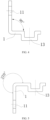
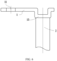
- the novel wire connection terminal includes a terminal substrate 1.
- the terminal substrate 1 is provided with a fixing portion for connecting with an electric device and a connecting portion for connecting with a wire 2.
- the fixing portion is provided with an assembly structure for being assembled with the electric device.
- the connecting portion is provided with a boss 13 formed by punching the connecting portion, and the boss 13 is used for connecting with the wire 2.
- the surface of the fixing portion or/and the connecting portion according to the present disclosure is provided with a plating layer, so as to prevent the terminal surface from being corroded due to long-term exposure to air and moisture, which may render terminal invalid.
- the plating layer may be provided on the entire surface of the fixing portion or/and the connecting portion, or on part of the surface where the terminal may be exposed when used.
- the plating layer according to the present disclosure has a thickness of 0.01 mm to 1000 ⁇ m.
- the inventor makes novel wire connection terminals with terminal substrates of the same thickness and material, provides plating layers of different thicknesses on the fixing portion or/and the connecting portion of the novel wire connection terminals, and makes welding joints using the novel wire connection terminals and the same wire. After 48 hours of salt spray experiments on the welding joints, the inventor has conducted a series of mechanical and electrical tests on the welding joints. As shown in Table 4.
- Table 4 Influence of different thicknesses of the anti-corrosion protection layers on the performance of electric joints
- Crosssectiona 1 area of the wire Thickness of anti-corrosion protection layers ( ⁇ m) 0.001 0.005 0.01 0.05 0.1 0.5 1 10 50 100 300 500 800 1000 1100 1200
- Pulling force of electric joints after 48 hours of salt spray experiments (N) 35 62 92 215 287 304 327 336 359 375 383 346 308 279 219 153 129 Voltage drop of electric joints after 48 hours of salt spray experiments (mV) 35 0.93 0.84 0.49 0.45 0.39 0.37 0.34 0.31 0.28 0.26 0.34 0.37 0.41 0.49 0.67 0.92
- the thickness of the plating layer of the novel wire connection terminal is more than 1000 ⁇ m, after the salt spray test, the pulling force of the corresponding welding joint is smaller than 200N and the voltage drop is greater than 0.5 mV, which does not satisfy the mechanical and electrical properties of the welding joint.
- the inventor sets the thickness of the plating layer to be between 0.01 ⁇ m and 1000 ⁇ m. A user can select a suitable thickness of the plating layer according to the actual use requirements.
- the terminal substrate 1 according to the present disclosure is a copper plate with a flatness not greater than ⁇ 85 mm.
- the flatness of the copper plate By controlling the flatness of the copper plate, it is possible to avoid the problem of inaccurate punching dimensions caused by uneven surface of the copper plate during punching.
- the copper plates with different flatness are tested, and the data in Table 5 are obtained.
- Table 5 Influence of flatness on dimensional accuracy of punching Flatness (mm) ⁇ 10 ⁇ 20 ⁇ 30 ⁇ 40 ⁇ 50 ⁇ 60 ⁇ 65 ⁇ 70 ⁇ 75 ⁇ 80 ⁇ 85 ⁇ 90 ⁇ 95 ⁇ 100 Machining accuracy of terminal ( ⁇ mm) 0.02 0.02 0.02 0.02 0.02 0.02 0.02 0.02 0.03 0.03 0.03 0.03 0.03 0.03 0.05 005 0.08
- the cross section of the boss 13 of the present disclosure is circular, oval, polygonal, or special-shaped, so the boss 13 can be connected to wires with differentshaped cross sections.
- the assembly structure of the present disclosure is a mounting hole 11, and the mounting hole 11 is a through hole formed by punching the fixing portion.
- the mounting hole 11 may be a fixed stud through which the through hole of the terminal fixing portion penetrates, and then fixed with a nut.
- the mounting hole 11 of the present disclosure is a circular hole, an oval hole, a waist-shaped hole, an oblong hole, a polygonal hole, or a special-shaped hole.
- the mounting hole 11 can be set to different shapes.
- the mounting size of the terminal on the fixed stud can be adjusted, thereby facilitating the installation of the wire harness.
- the novel wire connection terminal shown in FIG. 3 is basically the same as the First Embodiment except for the following differences.
- the assembly structure in the Second Embodiment according to the present disclosure is a mounting post 12 provided on the fixing portion.
- the mounting post 12 on the fixing portion in this embodiment may be matched and connected with the corresponding through hole.
- the cross section of the mounting post of the present disclosure is circular, oval, polygonal, or special-shaped. Likewise, different cross-sectional shapes of the mounting posts are intended to match through holes of different shapes.
- the mounting post according to the present disclosure is a threaded post, which can be more conveniently fitted with the nut, so that the terminal can be quickly fitted with the through hole.
- the mounting post according to the present disclosure is connected to the fixing portion by friction welding, resistance welding, ultrasonic welding, electromagnetic welding, pressure diffusion welding, arc welding, or riveting.
- the friction welding is to perform welding using friction welding equipment, which rotates a first workpiece and causes a second workpiece to apply pressure to the rotating first workpiece, so heat is generated by friction and the first and second workpieces are welded together by the pressure.
- the friction welding has advantages of fast welding speed without pollution such as noise, smoke, and strong light.
- the resistance welding uses resistance heat generated by the current passing through weldments and the contact place thereof as a heat source to heat the weldments locally, and at the same time, pressure is applied for welding.
- the advantages are that no filler metal is required, the productivity is high, the deformation of the weldment is small, and the automation is easy to realize.
- the ultrasonic welding is to transmit high frequency vibration waves to surfaces of two objects that need to be welded. Under pressure, fusion between the molecular layers is formed by rubbing the surfaces of the two objects against each other, which has the advantages of short welding time, no need of any flux, gas, or solder, no spark for welding, environmentally friendly and safe.
- the electromagnetic welding is to generate a strong magnetic field by utilizing instantaneous electric current, such that weldments are welded together under the action of magnetic field force, which has the advantages of non-contact welding, high welding speed, low welding internal stress, and high machining precision.
- the pressure diffusion welding is to press two weldments together, and metallurgically connect the weldments by interatomic diffusion through heat preservation, which has advantages that the weldments are not overheat or melted, the quality of the welding joint is high, a large-area weldment can be welded, the welding precision of the weldments is high, and the deformation is small.
- the arc welding is a physical phenomenon using an electric arc as a heat source and discharging electricity utilizing air, to convert the electric energy into the heat and mechanical energy required for welding, so as to achieve the purpose of connecting metal.
- the arc welding has advantages that the welding environment is not limited, and it is suitable for welding weldments with various metal materials, various thicknesses and various structural shapes.
- Plasma welding as a kind of arc welding, can be used to realize precise welding.
- the plasma arc has concentrated energy, high productivity, fast welding speed, small stress deformation and more stable arc.
- the riveting is a connection method of riveting and fitting the mounting post that is interference-fitted with the mounting hole of the fixing portion by pressure.
- the angle between the fixing portion and the connecting portion is 90 degrees and 270 degrees, respectively, and other configurations of the novel wire connection terminals are the same as those in the First Embodiment.
- the angle between the fixing portion and the connecting portion is more than 0 degrees, and less than or equal to 270 degrees.
- an angle is formed by punching between the fixing portion and the connecting portion, so as to adapt to different installation requirements of the terminal.
- the angle between the fixing portion and the connecting portion is equal to 0 degrees, the fixing portion and the connecting portion are bent in a reverse direction and attached to each other. In this case, rapid processing cannot be performed, and there is no use environment for actual use. Therefore, the angle between the fixing portion and the connecting portion is not set to 0 degrees.
- the angle between the fixing portion and the connecting portion is less than or equal to 270 degrees.
- the present disclosure also provides a welding joint, which includes a novel wire connection terminal according to any of the above solutions and a wire.
- the wire 2 is connected to a boss 13 of the novel wire connection terminal by welding.
- the welding may be friction welding, resistance welding, ultrasonic welding, electromagnetic welding, pressure diffusion welding, or arc welding.
- the friction welding is to perform welding using friction welding equipment, which rotates a first workpiece and causes a second workpiece to apply pressure to the rotating first workpiece, so heat is generated by friction and the first and second workpieces are welded together by the pressure.
- the friction welding has advantages of fast welding speed without pollution such as noise, smoke, and strong light.
- the resistance welding uses resistance heat generated by the current passing through weldments and the contact place thereof as a heat source to heat the weldments locally, and at the same time, pressure is applied for welding.
- the advantages are that no filler metal is required, the productivity is high, the deformation of the weldment is small, and the automation is easy to realize.
- the ultrasonic welding is to transmit high frequency vibration waves to surfaces of two objects that need to be welded. Under pressure, fusion between the molecular layers is formed by rubbing the surfaces of the two objects against each other, which has the advantages of short welding time, no need of any flux, gas, or solder, no spark for welding, environmentally friendly and safe.
- the electromagnetic welding is to generate a strong magnetic field by utilizing instantaneous electric current, such that weldments are welded together under the action of magnetic field force, which has the advantages of non-contact welding, high welding speed, low welding internal stress, and high machining precision.
- the pressure diffusion welding is to press two weldments together, and metallurgically connect the weldments by interatomic diffusion through heat preservation, which has advantages that the weldments are not overheat or melted, the quality of the welding joint is high, a large-area weldment can be welded, the welding precision of the weldments is high, and the deformation is small.
- the arc welding is a physical phenomenon using an electric arc as a heat source and discharging electricity utilizing air, to convert the electric energy into the heat and mechanical energy required for welding, so as to achieve the purpose of connecting metal.
- the arc welding has advantages that the welding environment is not limited, and it is suitable for welding weldments with various metal materials, various thicknesses and various structural shapes.
- Plasma welding as a kind of arc welding, can be used to realize precise welding.
- the plasma arc has concentrated energy, high productivity, fast welding speed, small stress deformation and more stable arc.
Landscapes
- Engineering & Computer Science (AREA)
- Manufacturing & Machinery (AREA)
- Connections Effected By Soldering, Adhesion, Or Permanent Deformation (AREA)
- Multi-Conductor Connections (AREA)
- Coupling Device And Connection With Printed Circuit (AREA)
- Manufacturing Of Electrical Connectors (AREA)
Applications Claiming Priority (2)
| Application Number | Priority Date | Filing Date | Title |
|---|---|---|---|
| CN202020456074.7U CN211858910U (zh) | 2020-04-01 | 2020-04-01 | 一种新型导线连接端子及焊接接头 |
| PCT/CN2021/084925 WO2021197425A1 (fr) | 2020-04-01 | 2021-04-01 | Nouvelle borne de raccordement de fil conducteur et joint de soudure |
Publications (4)
| Publication Number | Publication Date |
|---|---|
| EP4131661A1 true EP4131661A1 (fr) | 2023-02-08 |
| EP4131661A4 EP4131661A4 (fr) | 2023-10-18 |
| EP4131661C0 EP4131661C0 (fr) | 2024-10-23 |
| EP4131661B1 EP4131661B1 (fr) | 2024-10-23 |
Family
ID=73144389
Family Applications (1)
| Application Number | Title | Priority Date | Filing Date |
|---|---|---|---|
| EP21780183.6A Active EP4131661B1 (fr) | 2020-04-01 | 2021-04-01 | Nouvelle borne de raccordement de fil conducteur et joint de soudure |
Country Status (13)
| Country | Link |
|---|---|
| US (1) | US12362511B2 (fr) |
| EP (1) | EP4131661B1 (fr) |
| JP (1) | JP2023510043A (fr) |
| KR (1) | KR102754552B1 (fr) |
| CN (1) | CN211858910U (fr) |
| BR (1) | BR112022019895A2 (fr) |
| CA (1) | CA3173885A1 (fr) |
| ES (1) | ES2994954T3 (fr) |
| HU (1) | HUE069186T2 (fr) |
| MX (1) | MX2022012401A (fr) |
| PL (1) | PL4131661T3 (fr) |
| WO (1) | WO2021197425A1 (fr) |
| ZA (1) | ZA202211305B (fr) |
Cited By (1)
| Publication number | Priority date | Publication date | Assignee | Title |
|---|---|---|---|---|
| EP4503336A1 (fr) * | 2023-08-04 | 2025-02-05 | Siemens Aktiengesellschaft | Élément de contact pour la mise en contact électrique d'au moins deux éléments de contact électriques, agencement et procédé de mise en contact d'éléments de contact électriques au moyen d'un soudage laser |
Families Citing this family (2)
| Publication number | Priority date | Publication date | Assignee | Title |
|---|---|---|---|---|
| CN211858910U (zh) | 2020-04-01 | 2020-11-03 | 吉林省中赢高科技有限公司 | 一种新型导线连接端子及焊接接头 |
| EP4290573A1 (fr) * | 2022-06-08 | 2023-12-13 | Nexperia B.V. | Ensemble boîtier semi-conducteur et procédé de fabrication d'un tel ensemble boîtier semi-conducteur |
Family Cites Families (22)
| Publication number | Priority date | Publication date | Assignee | Title |
|---|---|---|---|---|
| ZA783792B (en) * | 1977-07-26 | 1979-07-25 | Marston Excelsior Ltd | Electrical connector |
| JP3438809B2 (ja) | 1998-01-28 | 2003-08-18 | ミヤチテクノス株式会社 | 端子部材に電線を溶接するためのレーザ溶接方法 |
| US6077096A (en) | 1999-03-10 | 2000-06-20 | Emhart Inc. | Weld stud |
| JP2003163302A (ja) * | 2001-11-28 | 2003-06-06 | Kyocera Corp | 半導体素子収納用パッケージおよび半導体装置 |
| JP4158889B2 (ja) * | 2002-09-30 | 2008-10-01 | 古河電気工業株式会社 | 端子付電線端末構造及び端子 |
| DE10302270A1 (de) * | 2003-01-22 | 2004-08-12 | Fröhlich, Bernhard | Kontaktstück für einen Batterieverbinder |
| JP2005073178A (ja) * | 2003-08-27 | 2005-03-17 | Kyocera Corp | 非放射性誘電体線路およびその製造方法 |
| CN101212094A (zh) * | 2006-12-31 | 2008-07-02 | 王明山 | 节省加工制程的插头导电刃压着结构 |
| JP5458931B2 (ja) * | 2010-02-15 | 2014-04-02 | 日立金属株式会社 | 端子付き電線 |
| JP5648154B2 (ja) * | 2010-11-30 | 2015-01-07 | 多摩川精機株式会社 | レゾルバステータの端子ピンへのリード線固定構造及び方法 |
| JP6288932B2 (ja) | 2013-04-11 | 2018-03-07 | 矢崎総業株式会社 | 電線と端子との接合構造 |
| JP2014235777A (ja) * | 2013-05-30 | 2014-12-15 | 矢崎総業株式会社 | 電線と端子の接合構造及び接合方法 |
| JP6020436B2 (ja) | 2013-12-16 | 2016-11-02 | 住友電装株式会社 | 電線接続用の端子および該端子の電線接続構造 |
| JP2016058182A (ja) * | 2014-09-08 | 2016-04-21 | 株式会社オートネットワーク技術研究所 | 端子付電線及び端子 |
| CN106684074B (zh) * | 2017-01-22 | 2023-08-01 | 嘉兴斯达半导体股份有限公司 | 一种新型压接型功率模块 |
| CN206595440U (zh) * | 2017-03-06 | 2017-10-27 | 深圳市土川投资管理有限公司 | 一种连接器的接线端子 |
| JP2019145263A (ja) * | 2018-02-19 | 2019-08-29 | 矢崎総業株式会社 | 端子付き電線 |
| WO2020105152A1 (fr) * | 2018-11-21 | 2020-05-28 | 株式会社オートネットワーク技術研究所 | Fil électrique équipé de bornes |
| CN209104263U (zh) * | 2018-11-28 | 2019-07-12 | 湖州道广科技有限公司 | 一种蓄电池端子 |
| CN210137032U (zh) * | 2019-06-13 | 2020-03-10 | 株洲时代龙友科技有限公司 | 连接器 |
| CN110289511A (zh) * | 2019-06-13 | 2019-09-27 | 株洲时代龙友科技有限公司 | 连接器及连接器的制作方法 |
| CN211858910U (zh) * | 2020-04-01 | 2020-11-03 | 吉林省中赢高科技有限公司 | 一种新型导线连接端子及焊接接头 |
-
2020
- 2020-04-01 CN CN202020456074.7U patent/CN211858910U/zh active Active
-
2021
- 2021-04-01 KR KR1020227037423A patent/KR102754552B1/ko active Active
- 2021-04-01 BR BR112022019895A patent/BR112022019895A2/pt unknown
- 2021-04-01 JP JP2022560268A patent/JP2023510043A/ja active Pending
- 2021-04-01 EP EP21780183.6A patent/EP4131661B1/fr active Active
- 2021-04-01 CA CA3173885A patent/CA3173885A1/fr active Pending
- 2021-04-01 MX MX2022012401A patent/MX2022012401A/es unknown
- 2021-04-01 PL PL21780183.6T patent/PL4131661T3/pl unknown
- 2021-04-01 HU HUE21780183A patent/HUE069186T2/hu unknown
- 2021-04-01 US US17/916,768 patent/US12362511B2/en active Active
- 2021-04-01 WO PCT/CN2021/084925 patent/WO2021197425A1/fr not_active Ceased
- 2021-04-01 ES ES21780183T patent/ES2994954T3/es active Active
-
2022
- 2022-10-14 ZA ZA2022/11305A patent/ZA202211305B/en unknown
Cited By (1)
| Publication number | Priority date | Publication date | Assignee | Title |
|---|---|---|---|---|
| EP4503336A1 (fr) * | 2023-08-04 | 2025-02-05 | Siemens Aktiengesellschaft | Élément de contact pour la mise en contact électrique d'au moins deux éléments de contact électriques, agencement et procédé de mise en contact d'éléments de contact électriques au moyen d'un soudage laser |
Also Published As
| Publication number | Publication date |
|---|---|
| ES2994954T3 (en) | 2025-02-04 |
| CA3173885A1 (fr) | 2021-10-07 |
| CN211858910U (zh) | 2020-11-03 |
| BR112022019895A2 (pt) | 2022-11-22 |
| PL4131661T3 (pl) | 2025-02-24 |
| EP4131661C0 (fr) | 2024-10-23 |
| EP4131661A4 (fr) | 2023-10-18 |
| ZA202211305B (en) | 2024-02-28 |
| WO2021197425A1 (fr) | 2021-10-07 |
| KR102754552B1 (ko) | 2025-01-14 |
| EP4131661B1 (fr) | 2024-10-23 |
| JP2023510043A (ja) | 2023-03-10 |
| US20230163503A1 (en) | 2023-05-25 |
| MX2022012401A (es) | 2022-10-27 |
| HUE069186T2 (hu) | 2025-02-28 |
| US12362511B2 (en) | 2025-07-15 |
| KR20220160067A (ko) | 2022-12-05 |
Similar Documents
| Publication | Publication Date | Title |
|---|---|---|
| EP4131661A1 (fr) | Nouvelle borne de raccordement de fil conducteur et joint de soudure | |
| EP4395086B1 (fr) | Mécanisme de transfert pour transmission d'énergie, douille de charge et véhicule à moteur | |
| US20200395690A1 (en) | Joint of copper terminal and aluminium conductor and ultrasonic welding method thereof | |
| CN206717300U (zh) | 电芯焊接工装 | |
| CN216251492U (zh) | 一种电能传输转接机构、充电插座和机动车辆 | |
| EP4459814A1 (fr) | Prise de charge facilement remplaçable et véhicule | |
| WO2024056047A1 (fr) | Nouvelle borne en composite cuivre-aluminium | |
| CN209912950U (zh) | 电池保护板和具有该电池保护板的电池 | |
| CN110834139A (zh) | 一种电阻点焊异种金属的方法 | |
| CN105810766B (zh) | 一种带有金属箔与复合导电带的电流引出装置 | |
| CN202455656U (zh) | 与印制电路板组装的金属基板以及印制电路板组件 | |
| CN117260175B (zh) | 一种具有中间层的冷板生产方法 | |
| EP4131671A1 (fr) | Connecteur profilé | |
| CN204809297U (zh) | 极耳固定结构及应用所述极耳固定结构的电池 | |
| CN100402217C (zh) | 载流金具超声波热浸锡及铜铝过渡双变性复合粘接 | |
| CN112589270A (zh) | 一种小型软包锂电池的激光焊接治具 | |
| CN116314845B (zh) | 集流体及含其的极片、其制备方法 | |
| CN217283569U (zh) | 一种便于焊接的隔热pcb板 | |
| CN115533235B (zh) | 大端子薄膜电容器的焊接方法、工装、焊片及生产方法 | |
| KR860000003B1 (ko) | 적층된 도전부재의 제조방법 | |
| CA3065848C (fr) | Joint de borne en cuivre et conducteur en aluminium et son procede de soudage par ultrasons | |
| JP2002075058A (ja) | 耐食性に優れた銅ブスバーおよびその製造方法 | |
| CN121670131A (zh) | 一种多层集流体与极耳的激光焊接方法 | |
| CN120186869A (zh) | 一种铝基板应用在bms中的结构及工艺 | |
| CN121491507A (zh) | 一种用于极耳预焊的防氧化电极、预焊系统及预焊成型方法 |
Legal Events
| Date | Code | Title | Description |
|---|---|---|---|
| STAA | Information on the status of an ep patent application or granted ep patent |
Free format text: STATUS: THE INTERNATIONAL PUBLICATION HAS BEEN MADE |
|
| PUAI | Public reference made under article 153(3) epc to a published international application that has entered the european phase |
Free format text: ORIGINAL CODE: 0009012 |
|
| STAA | Information on the status of an ep patent application or granted ep patent |
Free format text: STATUS: REQUEST FOR EXAMINATION WAS MADE |
|
| 17P | Request for examination filed |
Effective date: 20221028 |
|
| AK | Designated contracting states |
Kind code of ref document: A1 Designated state(s): AL AT BE BG CH CY CZ DE DK EE ES FI FR GB GR HR HU IE IS IT LI LT LU LV MC MK MT NL NO PL PT RO RS SE SI SK SM TR |
|
| P01 | Opt-out of the competence of the unified patent court (upc) registered |
Effective date: 20230411 |
|
| DAV | Request for validation of the european patent (deleted) | ||
| DAX | Request for extension of the european patent (deleted) | ||
| A4 | Supplementary search report drawn up and despatched |
Effective date: 20230915 |
|
| RIC1 | Information provided on ipc code assigned before grant |
Ipc: H01R 4/02 20060101ALI20230911BHEP Ipc: H01R 4/58 20060101AFI20230911BHEP |
|
| GRAP | Despatch of communication of intention to grant a patent |
Free format text: ORIGINAL CODE: EPIDOSNIGR1 |
|
| STAA | Information on the status of an ep patent application or granted ep patent |
Free format text: STATUS: GRANT OF PATENT IS INTENDED |
|
| INTG | Intention to grant announced |
Effective date: 20240708 |
|
| GRAS | Grant fee paid |
Free format text: ORIGINAL CODE: EPIDOSNIGR3 |
|
| GRAA | (expected) grant |
Free format text: ORIGINAL CODE: 0009210 |
|
| STAA | Information on the status of an ep patent application or granted ep patent |
Free format text: STATUS: THE PATENT HAS BEEN GRANTED |
|
| AK | Designated contracting states |
Kind code of ref document: B1 Designated state(s): AL AT BE BG CH CY CZ DE DK EE ES FI FR GB GR HR HU IE IS IT LI LT LU LV MC MK MT NL NO PL PT RO RS SE SI SK SM TR |
|
| REG | Reference to a national code |
Ref country code: GB Ref legal event code: FG4D |
|
| REG | Reference to a national code |
Ref country code: CH Ref legal event code: EP |
|
| REG | Reference to a national code |
Ref country code: DE Ref legal event code: R096 Ref document number: 602021020720 Country of ref document: DE |
|
| REG | Reference to a national code |
Ref country code: IE Ref legal event code: FG4D |
|
| U01 | Request for unitary effect filed |
Effective date: 20241108 |
|
| P04 | Withdrawal of opt-out of the competence of the unified patent court (upc) registered |
Free format text: CASE NUMBER: APP_61698/2024 Effective date: 20241118 |
|
| U07 | Unitary effect registered |
Designated state(s): AT BE BG DE DK EE FI FR IT LT LU LV MT NL PT RO SE SI Effective date: 20241121 |
|
| REG | Reference to a national code |
Ref country code: SK Ref legal event code: T3 Ref document number: E 45343 Country of ref document: SK |
|
| REG | Reference to a national code |
Ref country code: ES Ref legal event code: FG2A Ref document number: 2994954 Country of ref document: ES Kind code of ref document: T3 Effective date: 20250204 |
|
| REG | Reference to a national code |
Ref country code: HU Ref legal event code: AG4A Ref document number: E069186 Country of ref document: HU |
|
| PG25 | Lapsed in a contracting state [announced via postgrant information from national office to epo] |
Ref country code: IS Free format text: LAPSE BECAUSE OF FAILURE TO SUBMIT A TRANSLATION OF THE DESCRIPTION OR TO PAY THE FEE WITHIN THE PRESCRIBED TIME-LIMIT Effective date: 20250223 Ref country code: HR Free format text: LAPSE BECAUSE OF FAILURE TO SUBMIT A TRANSLATION OF THE DESCRIPTION OR TO PAY THE FEE WITHIN THE PRESCRIBED TIME-LIMIT Effective date: 20241023 |
|
| PG25 | Lapsed in a contracting state [announced via postgrant information from national office to epo] |
Ref country code: NO Free format text: LAPSE BECAUSE OF FAILURE TO SUBMIT A TRANSLATION OF THE DESCRIPTION OR TO PAY THE FEE WITHIN THE PRESCRIBED TIME-LIMIT Effective date: 20250123 |
|
| PG25 | Lapsed in a contracting state [announced via postgrant information from national office to epo] |
Ref country code: GR Free format text: LAPSE BECAUSE OF FAILURE TO SUBMIT A TRANSLATION OF THE DESCRIPTION OR TO PAY THE FEE WITHIN THE PRESCRIBED TIME-LIMIT Effective date: 20250124 |
|
| PG25 | Lapsed in a contracting state [announced via postgrant information from national office to epo] |
Ref country code: RS Free format text: LAPSE BECAUSE OF FAILURE TO SUBMIT A TRANSLATION OF THE DESCRIPTION OR TO PAY THE FEE WITHIN THE PRESCRIBED TIME-LIMIT Effective date: 20250123 |
|
| U21 | Renewal fee for the european patent with unitary effect paid with additional fee |
Year of fee payment: 5 Effective date: 20250526 |
|
| PG25 | Lapsed in a contracting state [announced via postgrant information from national office to epo] |
Ref country code: SM Free format text: LAPSE BECAUSE OF FAILURE TO SUBMIT A TRANSLATION OF THE DESCRIPTION OR TO PAY THE FEE WITHIN THE PRESCRIBED TIME-LIMIT Effective date: 20241023 |
|
| PGFP | Annual fee paid to national office [announced via postgrant information from national office to epo] |
Ref country code: ES Payment date: 20250527 Year of fee payment: 5 |
|
| PGFP | Annual fee paid to national office [announced via postgrant information from national office to epo] |
Ref country code: HU Payment date: 20250612 Year of fee payment: 5 |
|
| PGFP | Annual fee paid to national office [announced via postgrant information from national office to epo] |
Ref country code: CH Payment date: 20250526 Year of fee payment: 5 |
|
| PLBE | No opposition filed within time limit |
Free format text: ORIGINAL CODE: 0009261 |
|
| STAA | Information on the status of an ep patent application or granted ep patent |
Free format text: STATUS: NO OPPOSITION FILED WITHIN TIME LIMIT |
|
| 26N | No opposition filed |
Effective date: 20250724 |
|
| PG25 | Lapsed in a contracting state [announced via postgrant information from national office to epo] |
Ref country code: MC Free format text: LAPSE BECAUSE OF FAILURE TO SUBMIT A TRANSLATION OF THE DESCRIPTION OR TO PAY THE FEE WITHIN THE PRESCRIBED TIME-LIMIT Effective date: 20241023 |
|
| PGFP | Annual fee paid to national office [announced via postgrant information from national office to epo] |
Ref country code: GB Payment date: 20260326 Year of fee payment: 6 |
|
| PG25 | Lapsed in a contracting state [announced via postgrant information from national office to epo] |
Ref country code: IE Free format text: LAPSE BECAUSE OF NON-PAYMENT OF DUE FEES Effective date: 20250401 |
|
| PGFP | Annual fee paid to national office [announced via postgrant information from national office to epo] |
Ref country code: CZ Payment date: 20260324 Year of fee payment: 6 |
|
| PGFP | Annual fee paid to national office [announced via postgrant information from national office to epo] |
Ref country code: PL Payment date: 20260323 Year of fee payment: 6 |
|
| PGFP | Annual fee paid to national office [announced via postgrant information from national office to epo] |
Ref country code: SK Payment date: 20260324 Year of fee payment: 6 |
|
| U1N | Appointed representative for the unitary patent procedure changed after the registration of the unitary effect |
Representative=s name: MARKS & CLERK LLP; GB |