EP4131671A1 - Profilverbinder - Google Patents
Profilverbinder Download PDFInfo
- Publication number
- EP4131671A1 EP4131671A1 EP21778993.2A EP21778993A EP4131671A1 EP 4131671 A1 EP4131671 A1 EP 4131671A1 EP 21778993 A EP21778993 A EP 21778993A EP 4131671 A1 EP4131671 A1 EP 4131671A1
- Authority
- EP
- European Patent Office
- Prior art keywords
- welding
- core
- special
- connection terminal
- shaped joint
- Prior art date
- Legal status (The legal status is an assumption and is not a legal conclusion. Google has not performed a legal analysis and makes no representation as to the accuracy of the status listed.)
- Granted
Links
Images


Classifications
-
- H—ELECTRICITY
- H01—ELECTRIC ELEMENTS
- H01R—ELECTRICALLY-CONDUCTIVE CONNECTIONS; STRUCTURAL ASSOCIATIONS OF A PLURALITY OF MUTUALLY-INSULATED ELECTRICAL CONNECTING ELEMENTS; COUPLING DEVICES; CURRENT COLLECTORS
- H01R11/00—Individual connecting elements providing two or more spaced connecting locations for conductive members which are, or may be, thereby interconnected, e.g. end pieces for wires or cables supported by the wire or cable and having means for facilitating electrical connection to some other wire, terminal, or conductive member, blocks of binding posts
- H01R11/11—End pieces or tapping pieces for wires, supported by the wire and for facilitating electrical connection to some other wire, terminal or conductive member
-
- H—ELECTRICITY
- H01—ELECTRIC ELEMENTS
- H01R—ELECTRICALLY-CONDUCTIVE CONNECTIONS; STRUCTURAL ASSOCIATIONS OF A PLURALITY OF MUTUALLY-INSULATED ELECTRICAL CONNECTING ELEMENTS; COUPLING DEVICES; CURRENT COLLECTORS
- H01R4/00—Electrically-conductive connections between two or more conductive members in direct contact, i.e. touching one another; Means for effecting or maintaining such contact; Electrically-conductive connections having two or more spaced connecting locations for conductors and using contact members penetrating insulation
- H01R4/02—Soldered or welded connections
- H01R4/023—Soldered or welded connections between cables or wires and terminals
-
- B—PERFORMING OPERATIONS; TRANSPORTING
- B23—MACHINE TOOLS; METAL-WORKING NOT OTHERWISE PROVIDED FOR
- B23K—SOLDERING OR UNSOLDERING; WELDING; CLADDING OR PLATING BY SOLDERING OR WELDING; CUTTING BY APPLYING HEAT LOCALLY, e.g. FLAME CUTTING; WORKING BY LASER BEAM
- B23K31/00—Processes relevant to this subclass, specially adapted for particular articles or purposes, but not covered by any single one of main groups B23K1/00 - B23K28/00
- B23K31/02—Processes relevant to this subclass, specially adapted for particular articles or purposes, but not covered by any single one of main groups B23K1/00 - B23K28/00 relating to soldering or welding
-
- H—ELECTRICITY
- H01—ELECTRIC ELEMENTS
- H01R—ELECTRICALLY-CONDUCTIVE CONNECTIONS; STRUCTURAL ASSOCIATIONS OF A PLURALITY OF MUTUALLY-INSULATED ELECTRICAL CONNECTING ELEMENTS; COUPLING DEVICES; CURRENT COLLECTORS
- H01R4/00—Electrically-conductive connections between two or more conductive members in direct contact, i.e. touching one another; Means for effecting or maintaining such contact; Electrically-conductive connections having two or more spaced connecting locations for conductors and using contact members penetrating insulation
- H01R4/02—Soldered or welded connections
- H01R4/029—Welded connections
-
- B—PERFORMING OPERATIONS; TRANSPORTING
- B23—MACHINE TOOLS; METAL-WORKING NOT OTHERWISE PROVIDED FOR
- B23K—SOLDERING OR UNSOLDERING; WELDING; CLADDING OR PLATING BY SOLDERING OR WELDING; CUTTING BY APPLYING HEAT LOCALLY, e.g. FLAME CUTTING; WORKING BY LASER BEAM
- B23K2101/00—Articles made by soldering, welding or cutting
- B23K2101/36—Electric or electronic devices
- B23K2101/38—Conductors
-
- B—PERFORMING OPERATIONS; TRANSPORTING
- B23—MACHINE TOOLS; METAL-WORKING NOT OTHERWISE PROVIDED FOR
- B23K—SOLDERING OR UNSOLDERING; WELDING; CLADDING OR PLATING BY SOLDERING OR WELDING; CUTTING BY APPLYING HEAT LOCALLY, e.g. FLAME CUTTING; WORKING BY LASER BEAM
- B23K2103/00—Materials to be soldered, welded or cut
- B23K2103/08—Non-ferrous metals or alloys
- B23K2103/10—Aluminium or alloys thereof
-
- B—PERFORMING OPERATIONS; TRANSPORTING
- B23—MACHINE TOOLS; METAL-WORKING NOT OTHERWISE PROVIDED FOR
- B23K—SOLDERING OR UNSOLDERING; WELDING; CLADDING OR PLATING BY SOLDERING OR WELDING; CUTTING BY APPLYING HEAT LOCALLY, e.g. FLAME CUTTING; WORKING BY LASER BEAM
- B23K2103/00—Materials to be soldered, welded or cut
- B23K2103/08—Non-ferrous metals or alloys
- B23K2103/12—Copper or alloys thereof
-
- H—ELECTRICITY
- H01—ELECTRIC ELEMENTS
- H01R—ELECTRICALLY-CONDUCTIVE CONNECTIONS; STRUCTURAL ASSOCIATIONS OF A PLURALITY OF MUTUALLY-INSULATED ELECTRICAL CONNECTING ELEMENTS; COUPLING DEVICES; CURRENT COLLECTORS
- H01R2101/00—One pole
-
- H—ELECTRICITY
- H01—ELECTRIC ELEMENTS
- H01R—ELECTRICALLY-CONDUCTIVE CONNECTIONS; STRUCTURAL ASSOCIATIONS OF A PLURALITY OF MUTUALLY-INSULATED ELECTRICAL CONNECTING ELEMENTS; COUPLING DEVICES; CURRENT COLLECTORS
- H01R4/00—Electrically-conductive connections between two or more conductive members in direct contact, i.e. touching one another; Means for effecting or maintaining such contact; Electrically-conductive connections having two or more spaced connecting locations for conductors and using contact members penetrating insulation
- H01R4/10—Electrically-conductive connections between two or more conductive members in direct contact, i.e. touching one another; Means for effecting or maintaining such contact; Electrically-conductive connections having two or more spaced connecting locations for conductors and using contact members penetrating insulation effected solely by twisting, wrapping, bending, crimping, or other permanent deformation
- H01R4/18—Electrically-conductive connections between two or more conductive members in direct contact, i.e. touching one another; Means for effecting or maintaining such contact; Electrically-conductive connections having two or more spaced connecting locations for conductors and using contact members penetrating insulation effected solely by twisting, wrapping, bending, crimping, or other permanent deformation by crimping
- H01R4/187—Electrically-conductive connections between two or more conductive members in direct contact, i.e. touching one another; Means for effecting or maintaining such contact; Electrically-conductive connections having two or more spaced connecting locations for conductors and using contact members penetrating insulation effected solely by twisting, wrapping, bending, crimping, or other permanent deformation by crimping combined with soldering or welding
-
- H—ELECTRICITY
- H01—ELECTRIC ELEMENTS
- H01R—ELECTRICALLY-CONDUCTIVE CONNECTIONS; STRUCTURAL ASSOCIATIONS OF A PLURALITY OF MUTUALLY-INSULATED ELECTRICAL CONNECTING ELEMENTS; COUPLING DEVICES; CURRENT COLLECTORS
- H01R43/00—Apparatus or processes specially adapted for manufacturing, assembling, maintaining, or repairing of line connectors or current collectors or for joining electric conductors
- H01R43/02—Apparatus or processes specially adapted for manufacturing, assembling, maintaining, or repairing of line connectors or current collectors or for joining electric conductors for soldered or welded connections
- H01R43/0207—Ultrasonic-, H.F.-, cold- or impact welding
-
- H—ELECTRICITY
- H01—ELECTRIC ELEMENTS
- H01R—ELECTRICALLY-CONDUCTIVE CONNECTIONS; STRUCTURAL ASSOCIATIONS OF A PLURALITY OF MUTUALLY-INSULATED ELECTRICAL CONNECTING ELEMENTS; COUPLING DEVICES; CURRENT COLLECTORS
- H01R43/00—Apparatus or processes specially adapted for manufacturing, assembling, maintaining, or repairing of line connectors or current collectors or for joining electric conductors
- H01R43/02—Apparatus or processes specially adapted for manufacturing, assembling, maintaining, or repairing of line connectors or current collectors or for joining electric conductors for soldered or welded connections
- H01R43/0214—Resistance welding
-
- H—ELECTRICITY
- H01—ELECTRIC ELEMENTS
- H01R—ELECTRICALLY-CONDUCTIVE CONNECTIONS; STRUCTURAL ASSOCIATIONS OF A PLURALITY OF MUTUALLY-INSULATED ELECTRICAL CONNECTING ELEMENTS; COUPLING DEVICES; CURRENT COLLECTORS
- H01R43/00—Apparatus or processes specially adapted for manufacturing, assembling, maintaining, or repairing of line connectors or current collectors or for joining electric conductors
- H01R43/02—Apparatus or processes specially adapted for manufacturing, assembling, maintaining, or repairing of line connectors or current collectors or for joining electric conductors for soldered or welded connections
- H01R43/0221—Laser welding
-
- H—ELECTRICITY
- H01—ELECTRIC ELEMENTS
- H01R—ELECTRICALLY-CONDUCTIVE CONNECTIONS; STRUCTURAL ASSOCIATIONS OF A PLURALITY OF MUTUALLY-INSULATED ELECTRICAL CONNECTING ELEMENTS; COUPLING DEVICES; CURRENT COLLECTORS
- H01R43/00—Apparatus or processes specially adapted for manufacturing, assembling, maintaining, or repairing of line connectors or current collectors or for joining electric conductors
- H01R43/28—Apparatus or processes specially adapted for manufacturing, assembling, maintaining, or repairing of line connectors or current collectors or for joining electric conductors for wire processing before connecting to contact members, not provided for in groups H01R43/02 - H01R43/26
Definitions
- the present disclosure relates to the technical field of terminal connection, and in particular to a special-shaped joint.
- the installation position and installation space of the installation joint of the power distribution wire harness are more restricted, thus the angle between the cable and the terminal of the wire harness joint needs to be adjusted according to actual installation requirements.
- the cable of the wire harness is generally a multi-core conductor, it is soft and cannot be bent at a specified angle. Therefore, the angle between the cable and the terminal of the wire harness joint in the prior art is generally 180°, which cannot be used for electrical devices with specific installation requirements, thus seriously affecting the application range of the wire harness joint.
- the method in the prior art is to process an end of the terminal for fixing a cable and another end of the terminal for fixing an electrical device to have an included angle.
- the specific production method is: the terminal is firstly processed into a terminal with an included angle of 180°, and then the terminal with the included angle of 180° is bent into a terminal with other angles by bending.
- the problems of bending equipment and the rebound of the terminal itself it is difficult to ensure the accuracy of the angle of the bent terminal.
- the inner wall of the terminal will be compressed and the outer wall will be stretched, such that the internal stress at the bent position of the terminal with the included angle of 180° is extremely concentrated, which may cause the bent terminal to break at the bent position during use, thus leading to the invalid of the bent terminal and even a burning accident in serious cases.
- the present disclosure provides a special-shaped joint, which has simple structure, convenient assembly and wide application range.
- a special-shaped joint including at least one connection terminal for connecting an electrical device and at least one wire, with the connection terminal being connected to a core of the wire, and an included angle between the connection terminal and the core being greater than 0 degree and smaller than 180 degrees.
- the present disclosure discloses a special-shaped joint including at least one connection terminal for connecting an electrical device, and at least one wire; the connection terminal is connected to a core of the wire, so the special-shaped joint has a simple structure and is easy to assemble; an included angle between the connection terminal and the core is greater than 0 degree and smaller than 180 degrees, so that the special-shaped joint can be applied to the electrical device with a specific connection requirement for the included angle between the connection terminal and the wire, thus having a wide application range and breaking the limitation of the wire harness joint of the prior art in practical use.
- connection terminal 2. core; 3. insulation layer; 4. wire; 5. transfer terminal.
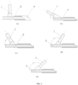
- FIG. 1 shows a first exemplary embodiment of the special-shaped joint according to the present disclosure, including at least one connection terminal 1 for connecting an electrical device and at least one wire 4.
- the connection terminal 1 is connected to a core 2 of the wire 4, and an included angle between the connection terminal 1 and the core 2 is greater than 0 degree and smaller than 180 degrees.
- the special-shaped joint of the present disclosure has a simple structure and is easy to assemble, and can be applied to an electrical device with a specific connection requirement for the included angle between the connection terminal 1 and the wire 4, thus having a wide application range.
- the included angle between the connection terminal 1 and the core 2 is any angle value between 0° and 180° (not including end point values).
- (a) to (e) of FIG. 1 respectively show structural schematics of the special-shaped joint with the angle between the connection terminal 1 and the core 2 being 90°, 30°, 60°, 120° and 135°.
- the angle between the connection terminal 1 and the core 2 of the special-shaped joint can be set according to actual installation requirements of the electrical device and the special-shaped joint.
- the number of the connection terminal 1 and the number of the wire 4 are both one.
- the material of the core 2 is aluminum, aluminum alloy, copper or copper alloy.
- copper and aluminum are both excellent electrical conductor materials, wherein (1) the resistivity of copper is 1.75 ⁇ 10-8 ⁇ m, which is second only to silver among the commonly used conductive metals in nature, therefore, the cores of most wires are made of copper; however, since the material of pure copper is soft and has poor mechanical properties, as a more exemplary solution, the material of the core 2 is a copper alloy; (2) the resistivity of aluminum is 2.83 ⁇ 10-8 ⁇ m, and aluminum is lighter and cheaper than copper; however, since the material of pure aluminum is soft and has poor mechanical properties, as a more exemplary technical solution, the material of the core 2 is an aluminum alloy.
- the core 2 is a single solid conductor.
- the solid conductor and the connection terminal 1 are connected by one selected from the group consisting of friction welding, resistance welding, ultrasonic welding, electromagnetic welding, pressure diffusion welding, arc welding, and laser welding, which will be described below.
- the angle between the connection terminal 1 and the core 2 is 90 degrees.
- the connection terminal 1 and the core 2 may be vertically connected by one selected from the group consisting of friction welding, resistance welding, ultrasonic welding, electromagnetic welding, pressure diffusion welding, arc welding, and laser welding. Therefore, the angle between the connection terminal 1 and the core 2 of the special-shaped joint can achieve higher accuracy.
- the special-shaped joint does not need to be subjected to bending treatment, so it has a longer service life compared with the connection terminal with 90 degrees in the prior art.
- connection terminal with 90 degrees formed by bending in the prior art and the special-shaped joint with 90 degrees in the present disclosure on mechanical properties and electrical properties of the wire harness joint
- the inventor has conducted a series of experiments on the mechanical properties, electrical properties and service life of the wire harness joints including the above two different connection terminals respectively and the same kind of wires.
- the experimental results are shown in Table 1.
- Table 1 the influence of the connection terminal with 90 degrees formed by bending and the special-shaped joint with 90 degrees on the pulling force and voltage drop of the wire harness joints Terminal type Connection terminal with 90 degrees Novel special-shaped joint with 90 degrees Connection terminal with 90 degrees Novel special-shaped joint with 90 degrees State After wire harness joint is made After aging test for 6000 hours Test Pulling force (N) Voltage drop (mV) Pulling force (N) Voltage drop (mV) Pulling force (N) Voltage drop (mV) Pulling force (N) Voltage drop (mV) 1 2645 0.36 3125 0.31 2156 0.43 2686 0.37 2 2561 0.34 3086 0.32 2138 0.46 2743 0.38 3 2772 0.36 3145 0.31 2182 0.45 2756 0.35 4 2744 0.38 3258 0.31 2162 0.46 2835 0.36 5 2642 0.36 3182 0.32 2084 0.43 2846 0.38 6 2665 0.38 3143 0.31 2126 0.46 2913 0.37 7 2785 0.37 3244 0.33 2067 0.45 2694 0.36 8 2556
- the pulling force of the wire harness joint including the connection terminal with 90 degrees that is formed by bending in the prior art is significantly lower than that of the wire harness joint including the special-shaped joint with 90 degrees of the present disclosure.
- the pulling force value of the wire harness joint including the connection terminal with 90 degrees that is formed by bending in the prior art is reduced, and the voltage drop value is increased, and unqualified products are prone to appear, which may result in function failure of the wire harness joint.
- the pulling force value and the voltage drop value of the wire harness joint including the special-shaped joint with 90 degrees of the present disclosure still meet the requirements of mechanical and electrical properties of the wire harness joint, and can ensure the function of the wire harness joint to be stable and reliable.
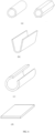
- connection terminal 1 is a hollow cylinder, and the cross section of the internal cavity of the connection terminal 1 is circular or oval or polygonal or special-shaped, such that the special-shaped joint can be connected with electrical devices having different plug ends. Moreover, if the cross section of the internal cavity of the connection terminal 1 is circular, the inner wall of the internal cavity of the connection terminal 1 is smooth or provided with an internal thread.
- the plug end of the electrical device is a cylinder with a smooth outer wall
- the cross section of the internal cavity of the connection terminal 1 is circular, and the inner wall of the internal cavity is smooth.
- the plug end of the electrical device is a cylinder with external thread on the outer wall
- the cross section of the internal cavity of the connection terminal 1 is circular, and the inner wall of the internal cavity is provided with internal threads matching the external threads.
- the plug end of the electrical device is a regular prism
- the cross section of the internal cavity of the connection terminal is a regular polygon matching the regular prism.
- connection terminal 1 is a solid cylinder with a circular, elliptical, polygonal, or special-shaped cross section.
- the connection terminal is a cylinder with a circular cross section and a smooth outer wall. If the plug end of the electrical device is a circular plug groove whose inner wall is provided with internal threads, the connection terminal is a cylinder, and the external surface of the connection terminal is provided with external threads matching the internal threads. If the connection terminal is a regular prism, the plug end of the electrical device is a plug groove matching the regular prism.
- connection terminals 1 and the wires 4 are in plural, such as 2, 3, etc., and the specific number can be set according to the actual demand of the electrical device.
- FIG. 3 only shows the structural schematic diagram of the special-shaped joint with the angle between the connection terminal 1 and the core 2 being 90 degrees.
- the included angle between the connection terminal 1 and the core 2 is any angle value between 0° and 180° (not including end point values), and can be set according to the actual installation requirements of the electrical device and the special-shaped joint.
- the number of the connection terminals 1 is two.
- the number of the connection terminal 1 is one, and the connection terminal 1 is located in the middle of the wire 4.
- the core 2 is a multi-core conductor
- the multi-core conductor having a hard structure is connected to the connection terminal 1 by one selected from the group consisting of friction welding, resistance welding, ultrasonic welding, electromagnetic welding, pressure diffusion welding, arc welding, and laser welding.
- the hard structure is formed from the multi-core conductor by one or more selected from the group consisting of ultrasonic welding, resistance welding, pressure diffusion welding, explosive welding, fusion welding, electromagnetic welding, arc welding, and laser welding.
- the hard structure also includes a transfer terminal 5 for connecting the multi-core conductor, and the hard structure is formed from the multi-core conductor and the transfer terminal 5 by one or more selected from the group consisting of crimping, ultrasonic welding, resistance welding, pressure diffusion welding, explosive welding, fusion welding, electromagnetic welding, arc welding, and laser welding.
- the transfer terminal 5 and a plurality of thin wires of the multi-core conductor are formed into the hard structure by one or more selected from the group consisting of crimping, ultrasonic welding, resistance welding, pressure diffusion welding, explosive welding, fusion welding, electromagnetic welding, arc welding, and laser welding.
- the distance between two adjacent thin wires is not greater than the diameter of the thin wire.
- the transfer terminal 5 is of a cylindrical structure, U-shaped structure, ring-shaped structure, or flat plate structure.
Landscapes
- Engineering & Computer Science (AREA)
- Mechanical Engineering (AREA)
- Connections Effected By Soldering, Adhesion, Or Permanent Deformation (AREA)
- Coupling Device And Connection With Printed Circuit (AREA)
Applications Claiming Priority (2)
| Application Number | Priority Date | Filing Date | Title |
|---|---|---|---|
| CN202020456558.1U CN211508140U (zh) | 2020-04-01 | 2020-04-01 | 一种异形接头 |
| PCT/CN2021/084904 WO2021197415A1 (zh) | 2020-04-01 | 2021-04-01 | 一种异形接头 |
Publications (4)
| Publication Number | Publication Date |
|---|---|
| EP4131671A1 true EP4131671A1 (de) | 2023-02-08 |
| EP4131671A4 EP4131671A4 (de) | 2023-10-11 |
| EP4131671B1 EP4131671B1 (de) | 2026-02-18 |
| EP4131671C0 EP4131671C0 (de) | 2026-02-18 |
Family
ID=72403645
Family Applications (1)
| Application Number | Title | Priority Date | Filing Date |
|---|---|---|---|
| EP21778993.2A Active EP4131671B1 (de) | 2020-04-01 | 2021-04-01 | Profilverbinder |
Country Status (9)
| Country | Link |
|---|---|
| US (1) | US20230307853A1 (de) |
| EP (1) | EP4131671B1 (de) |
| JP (1) | JP2023510046A (de) |
| CN (1) | CN211508140U (de) |
| CA (1) | CA3172441A1 (de) |
| ES (1) | ES3064108T3 (de) |
| MX (1) | MX2022012397A (de) |
| WO (1) | WO2021197415A1 (de) |
| ZA (1) | ZA202210951B (de) |
Families Citing this family (1)
| Publication number | Priority date | Publication date | Assignee | Title |
|---|---|---|---|---|
| CN211508140U (zh) * | 2020-04-01 | 2020-09-15 | 吉林省中赢高科技有限公司 | 一种异形接头 |
Family Cites Families (37)
| Publication number | Priority date | Publication date | Assignee | Title |
|---|---|---|---|---|
| JPS5443588A (en) * | 1977-09-12 | 1979-04-06 | Mitsubishi Electric Corp | Jointing method of stranded copper wire |
| US4679888A (en) * | 1982-02-05 | 1987-07-14 | Amp Incorporated | Electrical terminal and a method of making it |
| JPH0323664Y2 (de) * | 1986-05-01 | 1991-05-23 | ||
| JPH1131450A (ja) * | 1997-05-12 | 1999-02-02 | Yazaki Corp | ヒュージブルリンクの取付方法並びに該方法に用いる端子及びヒュージブルリンクハウジング |
| EP1156552B1 (de) * | 2000-03-07 | 2006-06-21 | Sumitomo Wiring Systems, Ltd. | Anordnung zum Vorbeugen von falsch Anschliessen von Batterieklemmen, Batterie und Kontaktklemmen |
| JP3923395B2 (ja) * | 2001-09-26 | 2007-05-30 | 矢崎総業株式会社 | 端子金具 |
| JP3912106B2 (ja) * | 2001-12-27 | 2007-05-09 | 住友電装株式会社 | アース端子 |
| US6670555B2 (en) * | 2002-02-20 | 2003-12-30 | Autonetworks Technologies, Ltd. | Terminal |
| JP4374187B2 (ja) * | 2002-12-20 | 2009-12-02 | 矢崎総業株式会社 | 端子と被覆電線との接続方法 |
| JP2004281068A (ja) * | 2003-03-12 | 2004-10-07 | Nihon If Kk | ケーブル端末用モールドピン |
| EP1984982A2 (de) * | 2006-02-09 | 2008-10-29 | LifeSync Corporation | Steckverbinder für gedruckte schaltung |
| US7160157B1 (en) * | 2006-03-17 | 2007-01-09 | Yazaki North America, Inc. | Twist-lock terminal connection system |
| JP2007305314A (ja) * | 2006-05-08 | 2007-11-22 | Hitachi Cable Ltd | 接続端子付きケーブルとその製造方法、並びに接続端子とケーブルとの超音波溶接方法および超音波溶接機 |
| US20090075528A1 (en) * | 2007-09-17 | 2009-03-19 | Thomas & Betts International, Inc. | 90-Degree ferrule and pin terminals |
| FR2923739A1 (fr) * | 2007-11-16 | 2009-05-22 | Valeo Systemes De Liaison Sa | Piece a souder et procede de soudure a etancheite amelioree |
| JP5131981B2 (ja) * | 2008-07-16 | 2013-01-30 | 矢崎総業株式会社 | 電気接続箱の端子装着構造 |
| DE102011017070B4 (de) * | 2011-04-14 | 2013-10-31 | Auto-Kabel Management Gmbh | Herstellung eines elektrischen Kabels sowie Verfahren zur Herstellung einer Verbindung |
| US8480423B2 (en) * | 2011-08-16 | 2013-07-09 | Tyco Electronics Corporation | Contact region of an electrically conductive member |
| JP6288932B2 (ja) * | 2013-04-11 | 2018-03-07 | 矢崎総業株式会社 | 電線と端子との接合構造 |
| JP2015076208A (ja) * | 2013-10-07 | 2015-04-20 | 矢崎総業株式会社 | 電線の端子接合構造及び抵抗溶接用電極、電線の端子接合方法 |
| DE102013017660B4 (de) * | 2013-10-25 | 2015-06-03 | Auto-Kabel Management Gmbh | Elektrische Anschlusskonsole für KFZ Bordnetzleitung |
| JP2015118832A (ja) * | 2013-12-19 | 2015-06-25 | 住友電装株式会社 | ワイヤーハーネスおよびその製造方法 |
| JP6585884B2 (ja) * | 2014-08-04 | 2019-10-02 | 株式会社フジクラ | 端子付き電線の製造方法 |
| DE102014012489B4 (de) * | 2014-08-27 | 2025-02-06 | Auto-Kabel Management Gmbh | Anschlussteil für Aluminiumleitungen |
| CN204156176U (zh) * | 2014-09-22 | 2015-02-11 | 李德琪 | 具有多个导线穿接方向的电源连接器 |
| CN205016744U (zh) * | 2015-08-17 | 2016-02-03 | 富士康(昆山)电脑接插件有限公司 | 线缆连接器组件 |
| JP6574736B2 (ja) * | 2016-05-31 | 2019-09-11 | 矢崎総業株式会社 | 端子付き電線の製造方法 |
| DE102016124583B3 (de) * | 2016-12-16 | 2018-02-15 | Auto-Kabel Management Gmbh | Fügen eines Anschlusselements mit einem Litzenleiter |
| US10103456B1 (en) * | 2017-05-26 | 2018-10-16 | AFC Cable Systems, Inc. | Electrica spring-terminal |
| CN107104292A (zh) * | 2017-06-05 | 2017-08-29 | 吉林省中赢高科技有限公司 | 一种铜端子与铝导线的接头及其电阻焊接方法 |
| CN107123867B (zh) * | 2017-06-05 | 2019-05-10 | 吉林省中赢高科技有限公司 | 一种铜端子与铝导线的接头及其磁感应焊接方法 |
| CN207134495U (zh) * | 2017-06-05 | 2018-03-23 | 吉林省中赢高科技有限公司 | 一种铜端子与铝导线的接头 |
| JP2019153418A (ja) * | 2018-03-01 | 2019-09-12 | 矢崎総業株式会社 | 端子付き電線および端子付き電線の製造方法 |
| JP7336453B2 (ja) * | 2018-03-13 | 2023-08-31 | ヒドロ・エクストゥルーデッド・ソリューションズ・アーエス | フラットケーブル接続部 |
| DE102018116599A1 (de) * | 2018-07-10 | 2020-01-16 | Phoenix Contact E-Mobility Gmbh | Verfahren zum Verbinden eines elektrischen Leiters mit einem Kontaktelement |
| CN208904266U (zh) * | 2018-11-27 | 2019-05-24 | 深圳市大疆创新科技有限公司 | 电源线、电源组件及无人机 |
| CN211508140U (zh) * | 2020-04-01 | 2020-09-15 | 吉林省中赢高科技有限公司 | 一种异形接头 |
-
2020
- 2020-04-01 CN CN202020456558.1U patent/CN211508140U/zh active Active
-
2021
- 2021-04-01 ES ES21778993T patent/ES3064108T3/es active Active
- 2021-04-01 CA CA3172441A patent/CA3172441A1/en active Pending
- 2021-04-01 JP JP2022560372A patent/JP2023510046A/ja active Pending
- 2021-04-01 MX MX2022012397A patent/MX2022012397A/es unknown
- 2021-04-01 EP EP21778993.2A patent/EP4131671B1/de active Active
- 2021-04-01 WO PCT/CN2021/084904 patent/WO2021197415A1/zh not_active Ceased
- 2021-04-01 US US17/915,973 patent/US20230307853A1/en not_active Abandoned
-
2022
- 2022-10-05 ZA ZA2022/10951A patent/ZA202210951B/en unknown
Also Published As
| Publication number | Publication date |
|---|---|
| CN211508140U (zh) | 2020-09-15 |
| CA3172441A1 (en) | 2021-10-07 |
| ZA202210951B (en) | 2023-05-31 |
| WO2021197415A1 (zh) | 2021-10-07 |
| EP4131671B1 (de) | 2026-02-18 |
| EP4131671C0 (de) | 2026-02-18 |
| JP2023510046A (ja) | 2023-03-10 |
| EP4131671A4 (de) | 2023-10-11 |
| US20230307853A1 (en) | 2023-09-28 |
| ES3064108T3 (en) | 2026-04-22 |
| MX2022012397A (es) | 2022-10-20 |
Similar Documents
| Publication | Publication Date | Title |
|---|---|---|
| US20250192458A1 (en) | Electric energy transmission assembly and vehicle | |
| WO2023024971A1 (zh) | 一种电能传输转接机构、充电插座和机动车辆 | |
| JP7465207B2 (ja) | 銅端子とアルミ導線との継手及びその磁気誘導溶接方法 | |
| EP4459814A1 (de) | Einfach austauschbare ladesteckdose und fahrzeug | |
| JP2011210481A (ja) | 電極端子、及び電極端子の製造方法 | |
| EP4131661B1 (de) | Neuartiger anschluss für einen leitenden draht und schweissverbindung | |
| US12381335B2 (en) | Electric energy transmission joint and preparation method therefor | |
| EP4131671A1 (de) | Profilverbinder | |
| CN115954689A (zh) | 一种新型铜铝复合端子 | |
| EP4496156A1 (de) | Mehradrige elektrische verbinderanordnung und fahrzeug | |
| EP4651311A1 (de) | Elektrische verbindungsanordnung | |
| CN217823616U (zh) | 一种多芯电连接器总成和车辆 | |
| CN217215265U (zh) | 一种可释放应力的线缆密封结构及一种车辆 | |
| CN217823495U (zh) | 一种连接器柔性连接结构及一种车辆 | |
| CN218569255U (zh) | 一种电连接件及电连接结构 | |
| WO2023174290A1 (zh) | 一种连接器柔性连接结构及一种车辆 | |
| WO2023040884A1 (zh) | 能够选择出线角度的充电座结构 | |
| CN223285297U (zh) | 一种隔爆型接线端子结构 | |
| CN222601431U (zh) | 一种电连接结构 | |
| CN219144518U (zh) | 一种铝芯光伏电缆导体连接装置 | |
| EP4372923B1 (de) | Steckklemme | |
| CN111211460A (zh) | 一种高压设备导线与金属内筒的电连接方法及连接装置 | |
| RU2164848C2 (ru) | Способ лазерной сварки тонких проводников | |
| KR200355394Y1 (ko) | 자동차 용접장치용 고압 케이블 | |
| CN121670131A (zh) | 一种多层集流体与极耳的激光焊接方法 |
Legal Events
| Date | Code | Title | Description |
|---|---|---|---|
| STAA | Information on the status of an ep patent application or granted ep patent |
Free format text: STATUS: THE INTERNATIONAL PUBLICATION HAS BEEN MADE |
|
| PUAI | Public reference made under article 153(3) epc to a published international application that has entered the european phase |
Free format text: ORIGINAL CODE: 0009012 |
|
| STAA | Information on the status of an ep patent application or granted ep patent |
Free format text: STATUS: REQUEST FOR EXAMINATION WAS MADE |
|
| 17P | Request for examination filed |
Effective date: 20221014 |
|
| AK | Designated contracting states |
Kind code of ref document: A1 Designated state(s): AL AT BE BG CH CY CZ DE DK EE ES FI FR GB GR HR HU IE IS IT LI LT LU LV MC MK MT NL NO PL PT RO RS SE SI SK SM TR |
|
| P01 | Opt-out of the competence of the unified patent court (upc) registered |
Effective date: 20230411 |
|
| DAV | Request for validation of the european patent (deleted) | ||
| DAX | Request for extension of the european patent (deleted) | ||
| REG | Reference to a national code |
Ref country code: DE Ref legal event code: R079 Ipc: H01R0004020000 Ref country code: DE Ref legal event code: R079 Ref document number: 602021048255 Country of ref document: DE Free format text: PREVIOUS MAIN CLASS: H01R0035040000 Ipc: H01R0004020000 |
|
| A4 | Supplementary search report drawn up and despatched |
Effective date: 20230911 |
|
| RIC1 | Information provided on ipc code assigned before grant |
Ipc: H01R 43/02 20060101ALN20230905BHEP Ipc: B23K 31/02 20060101ALI20230905BHEP Ipc: H01R 4/02 20060101AFI20230905BHEP |
|
| STAA | Information on the status of an ep patent application or granted ep patent |
Free format text: STATUS: EXAMINATION IS IN PROGRESS |
|
| 17Q | First examination report despatched |
Effective date: 20240606 |
|
| RIC1 | Information provided on ipc code assigned before grant |
Ipc: H01R 4/02 20060101AFI20250731BHEP Ipc: B23K 31/02 20060101ALI20250731BHEP Ipc: H01R 43/02 20060101ALN20250731BHEP |
|
| GRAP | Despatch of communication of intention to grant a patent |
Free format text: ORIGINAL CODE: EPIDOSNIGR1 |
|
| STAA | Information on the status of an ep patent application or granted ep patent |
Free format text: STATUS: GRANT OF PATENT IS INTENDED |
|
| RIC1 | Information provided on ipc code assigned before grant |
Ipc: H01R 4/02 20060101AFI20250911BHEP Ipc: B23K 31/02 20060101ALI20250911BHEP Ipc: H01R 43/02 20060101ALN20250911BHEP |
|
| INTG | Intention to grant announced |
Effective date: 20250925 |
|
| GRAS | Grant fee paid |
Free format text: ORIGINAL CODE: EPIDOSNIGR3 |
|
| GRAA | (expected) grant |
Free format text: ORIGINAL CODE: 0009210 |
|
| STAA | Information on the status of an ep patent application or granted ep patent |
Free format text: STATUS: THE PATENT HAS BEEN GRANTED |
|
| AK | Designated contracting states |
Kind code of ref document: B1 Designated state(s): AL AT BE BG CH CY CZ DE DK EE ES FI FR GB GR HR HU IE IS IT LI LT LU LV MC MK MT NL NO PL PT RO RS SE SI SK SM TR |
|
| REG | Reference to a national code |
Ref country code: CH Ref legal event code: F10 Free format text: ST27 STATUS EVENT CODE: U-0-0-F10-F00 (AS PROVIDED BY THE NATIONAL OFFICE) Effective date: 20260218 Ref country code: GB Ref legal event code: FG4D |
|
| REG | Reference to a national code |
Ref country code: IE Ref legal event code: FG4D |
|
| REG | Reference to a national code |
Ref country code: DE Ref legal event code: R096 Ref document number: 602021048255 Country of ref document: DE |
|
| U01 | Request for unitary effect filed |
Effective date: 20260226 |
|
| P04 | Withdrawal of opt-out of the competence of the unified patent court (upc) registered |
Free format text: CASE NUMBER: UPC_APP_19570_1/2023 Effective date: 20260304 |
|
| U07 | Unitary effect registered |
Designated state(s): AT BE BG DE DK EE FI FR IT LT LU LV MT NL PT RO SE SI Effective date: 20260304 |
|
| PGFP | Annual fee paid to national office [announced via postgrant information from national office to epo] |
Ref country code: GB Payment date: 20260324 Year of fee payment: 6 |
|
| REG | Reference to a national code |
Ref country code: ES Ref legal event code: FG2A Ref document number: 3064108 Country of ref document: ES Kind code of ref document: T3 Effective date: 20260422 |
|
| U20 | Renewal fee for the european patent with unitary effect paid |
Year of fee payment: 6 Effective date: 20260319 |