EP4131690A1 - Ausgleichsvorrichtung und ausgleichssystem - Google Patents
Ausgleichsvorrichtung und ausgleichssystem Download PDFInfo
- Publication number
- EP4131690A1 EP4131690A1 EP21781597.6A EP21781597A EP4131690A1 EP 4131690 A1 EP4131690 A1 EP 4131690A1 EP 21781597 A EP21781597 A EP 21781597A EP 4131690 A1 EP4131690 A1 EP 4131690A1
- Authority
- EP
- European Patent Office
- Prior art keywords
- balancer
- tension
- wire member
- control unit
- actuator
- Prior art date
- Legal status (The legal status is an assumption and is not a legal conclusion. Google has not performed a legal analysis and makes no representation as to the accuracy of the status listed.)
- Withdrawn
Links
- 230000008859 change Effects 0.000 claims description 37
- 239000010720 hydraulic oil Substances 0.000 claims description 31
- 230000007246 mechanism Effects 0.000 claims description 23
- 238000004891 communication Methods 0.000 claims description 18
- 230000005540 biological transmission Effects 0.000 claims description 13
- 239000003921 oil Substances 0.000 claims description 13
- JEIPFZHSYJVQDO-UHFFFAOYSA-N iron(III) oxide Inorganic materials O=[Fe]O[Fe]=O JEIPFZHSYJVQDO-UHFFFAOYSA-N 0.000 claims description 9
- 230000003449 preventive effect Effects 0.000 claims description 7
- 239000011261 inert gas Substances 0.000 claims description 6
- 238000012986 modification Methods 0.000 description 60
- 230000004048 modification Effects 0.000 description 60
- 238000001514 detection method Methods 0.000 description 30
- 239000000470 constituent Substances 0.000 description 13
- 230000033001 locomotion Effects 0.000 description 13
- 238000010586 diagram Methods 0.000 description 11
- 238000000034 method Methods 0.000 description 5
- 239000000463 material Substances 0.000 description 4
- 230000000694 effects Effects 0.000 description 3
- 230000006870 function Effects 0.000 description 3
- IJGRMHOSHXDMSA-UHFFFAOYSA-N Atomic nitrogen Chemical compound N#N IJGRMHOSHXDMSA-UHFFFAOYSA-N 0.000 description 2
- 230000005483 Hooke's law Effects 0.000 description 2
- 238000013459 approach Methods 0.000 description 2
- 230000015572 biosynthetic process Effects 0.000 description 2
- 230000000737 periodic effect Effects 0.000 description 2
- 230000008569 process Effects 0.000 description 2
- 230000008602 contraction Effects 0.000 description 1
- 230000007423 decrease Effects 0.000 description 1
- 238000013461 design Methods 0.000 description 1
- 239000007789 gas Substances 0.000 description 1
- 238000009434 installation Methods 0.000 description 1
- 238000005259 measurement Methods 0.000 description 1
- 229910052757 nitrogen Inorganic materials 0.000 description 1
- 238000012545 processing Methods 0.000 description 1
- 238000007789 sealing Methods 0.000 description 1
- 230000008054 signal transmission Effects 0.000 description 1
- 239000000758 substrate Substances 0.000 description 1
- 230000001360 synchronised effect Effects 0.000 description 1
Images


Classifications
-
- H—ELECTRICITY
- H02—GENERATION; CONVERSION OR DISTRIBUTION OF ELECTRIC POWER
- H02G—INSTALLATION OF ELECTRIC CABLES OR LINES, OR OF COMBINED OPTICAL AND ELECTRIC CABLES OR LINES
- H02G7/00—Overhead installations of electric lines or cables
- H02G7/02—Devices for adjusting or maintaining mechanical tension, e.g. take-up device
-
- B—PERFORMING OPERATIONS; TRANSPORTING
- B60—VEHICLES IN GENERAL
- B60M—POWER SUPPLY LINES, AND DEVICES ALONG RAILS, FOR ELECTRICALLY- PROPELLED VEHICLES
- B60M1/00—Power supply lines for contact with collector on vehicle
- B60M1/12—Trolley lines; Accessories therefor
- B60M1/26—Compensation means for variation in length
-
- F—MECHANICAL ENGINEERING; LIGHTING; HEATING; WEAPONS; BLASTING
- F15—FLUID-PRESSURE ACTUATORS; HYDRAULICS OR PNEUMATICS IN GENERAL
- F15B—SYSTEMS ACTING BY MEANS OF FLUIDS IN GENERAL; FLUID-PRESSURE ACTUATORS, e.g. SERVOMOTORS; DETAILS OF FLUID-PRESSURE SYSTEMS, NOT OTHERWISE PROVIDED FOR
- F15B13/00—Details of servomotor systems ; Valves for servomotor systems
- F15B13/02—Fluid distribution or supply devices characterised by their adaptation to the control of servomotors
- F15B13/04—Fluid distribution or supply devices characterised by their adaptation to the control of servomotors for use with a single servomotor
- F15B13/042—Fluid distribution or supply devices characterised by their adaptation to the control of servomotors for use with a single servomotor operated by fluid pressure
-
- F—MECHANICAL ENGINEERING; LIGHTING; HEATING; WEAPONS; BLASTING
- F15—FLUID-PRESSURE ACTUATORS; HYDRAULICS OR PNEUMATICS IN GENERAL
- F15B—SYSTEMS ACTING BY MEANS OF FLUIDS IN GENERAL; FLUID-PRESSURE ACTUATORS, e.g. SERVOMOTORS; DETAILS OF FLUID-PRESSURE SYSTEMS, NOT OTHERWISE PROVIDED FOR
- F15B13/00—Details of servomotor systems ; Valves for servomotor systems
- F15B13/02—Fluid distribution or supply devices characterised by their adaptation to the control of servomotors
- F15B13/06—Fluid distribution or supply devices characterised by their adaptation to the control of servomotors for use with two or more servomotors
-
- F—MECHANICAL ENGINEERING; LIGHTING; HEATING; WEAPONS; BLASTING
- F15—FLUID-PRESSURE ACTUATORS; HYDRAULICS OR PNEUMATICS IN GENERAL
- F15B—SYSTEMS ACTING BY MEANS OF FLUIDS IN GENERAL; FLUID-PRESSURE ACTUATORS, e.g. SERVOMOTORS; DETAILS OF FLUID-PRESSURE SYSTEMS, NOT OTHERWISE PROVIDED FOR
- F15B15/00—Fluid-actuated devices for displacing a member from one position to another; Gearing associated therewith
- F15B15/08—Characterised by the construction of the motor unit
- F15B15/14—Characterised by the construction of the motor unit of the straight-cylinder type
- F15B15/1423—Component parts; Constructional details
- F15B15/1457—Piston rods
-
- B—PERFORMING OPERATIONS; TRANSPORTING
- B60—VEHICLES IN GENERAL
- B60L—PROPULSION OF ELECTRICALLY-PROPELLED VEHICLES; SUPPLYING ELECTRIC POWER FOR AUXILIARY EQUIPMENT OF ELECTRICALLY-PROPELLED VEHICLES; ELECTRODYNAMIC BRAKE SYSTEMS FOR VEHICLES IN GENERAL; MAGNETIC SUSPENSION OR LEVITATION FOR VEHICLES; MONITORING OPERATING VARIABLES OF ELECTRICALLY-PROPELLED VEHICLES; ELECTRIC SAFETY DEVICES FOR ELECTRICALLY-PROPELLED VEHICLES
- B60L2200/00—Type of vehicles
- B60L2200/26—Rail vehicles
-
- B—PERFORMING OPERATIONS; TRANSPORTING
- B60—VEHICLES IN GENERAL
- B60Y—INDEXING SCHEME RELATING TO ASPECTS CROSS-CUTTING VEHICLE TECHNOLOGY
- B60Y2200/00—Type of vehicle
- B60Y2200/30—Railway vehicles
-
- B—PERFORMING OPERATIONS; TRANSPORTING
- B60—VEHICLES IN GENERAL
- B60Y—INDEXING SCHEME RELATING TO ASPECTS CROSS-CUTTING VEHICLE TECHNOLOGY
- B60Y2200/00—Type of vehicle
- B60Y2200/90—Vehicles comprising electric prime movers
- B60Y2200/91—Electric vehicles
-
- F—MECHANICAL ENGINEERING; LIGHTING; HEATING; WEAPONS; BLASTING
- F15—FLUID-PRESSURE ACTUATORS; HYDRAULICS OR PNEUMATICS IN GENERAL
- F15B—SYSTEMS ACTING BY MEANS OF FLUIDS IN GENERAL; FLUID-PRESSURE ACTUATORS, e.g. SERVOMOTORS; DETAILS OF FLUID-PRESSURE SYSTEMS, NOT OTHERWISE PROVIDED FOR
- F15B2211/00—Circuits for servomotor systems
- F15B2211/20—Fluid pressure source, e.g. accumulator or variable axial piston pump
- F15B2211/205—Systems with pumps
Definitions
- the present invention relates to a balancer and a balancer system.
- a current collector (a pantograph) on a roof of a train comes into contact with an overhead trolley wire, whereby electric energy is supplied to the train via the trolley wire.
- the tension of the overhead wire needs to be constant.
- a balancer is used to adjust the tension varying with temperature and wear to be constant (for example, see Patent Literature 1).
- the balancer disclosed in Patent Literature 1 includes a plurality of coil springs expanding and contracting in the direction of tension adjustment, and thereby adjusts the tension of the overhead wire.
- Patent Literature 1 Japanese Patent No. 3666971
- an object of the present invention is to provide a balancer and a balancer system that are capable of reducing the rate of change in tension while substantially preventing an increase in size.
- a balancer includes: an actuator configured to adjust a tension of a wire member; a tension sensor disposed between the wire member and the actuator and configured to detect the tension of the wire member; and a drive control unit configured to control the actuator, based on the tension of the wire member detected by the tension sensor.
- the actuator includes: a hydraulic cylinder, a hydraulic pump configured to supply a hydraulic oil to the hydraulic cylinder, and a piston rod disposed to be freely movable forward and backward with respect to the hydraulic cylinder and configured to move by the hydraulic oil supplied to the hydraulic cylinder.
- the drive control unit is configured to detect expansion of the wire member, based on a position of the piston rod after the wire member is adjusted to have a set tension.
- the drive control unit is configured to detect wear of the wire member, based on a transmission time of a signal transmitted via the wire member to another balancer paired with the balancer.
- the drive control unit is configured to acquire information on a tension of another balancer paired with the balancer, and calculate a driving amount of the actuator of the balancer including the drive control unit and an actuator of the other balancer.
- the above-described balancer according to the present invention further includes a rust-preventing mechanism configured to prevent the piston rod from rusting.
- the rust-preventing mechanism is configured to hermetically seal the piston rod in an inert gas atmosphere.
- the rust-preventing mechanism is configured to apply a rust preventive oil to the piston rod.
- the wire member includes a trolley wire configured to come into contact with a pantograph of a train
- the drive control unit is configured to cause the tension sensor to detect the tension of the wire member at a predetermined time before a time when the train passes through the trolley wire targeted for control, and control the actuator, based on the detected tension.
- a balancer system includes: a first balancer connected to one end of a wire member and configured to adjust a tension of the wire member, and a second balancer connected to another end of the same wire member shared with the first balancer, and configured to adjust the tension of the wire member, wherein the first balancer includes: a first actuator configured to adjust the tension of the wire member; a first tension sensor disposed between the wire member and the first actuator and configured to detect the tension of the wire member; a first drive control unit configured to control the first actuator, based on the tension of the wire member detected by the first tension sensor; and a first communication unit to communicate with the second balancer, and the first balancer includes: a second actuator configured to adjust the tension of the wire member; a second tension sensor disposed between the wire member and the second actuator and configured to detect the tension of the wire member; a second drive control unit configured to control the second actuator, based on the tension of the wire member detected by the second tension sensor; and a second communication unit configured to communicate with the first balancer
- the first drive control unit is configured to detect wear of the wire member, based on a transmission time of a signal transmitted to the second balancer via the wire member.
- the first drive control unit is configured to acquire information on a tension of the second balancer, and calculate a driving amount of the actuators of the first balancer and the second balancer.
- the first actuator includes: a first hydraulic cylinder; a first hydraulic pump configured to supply a first hydraulic oil to the first hydraulic cylinder; and a first piston rod disposed to be freely movable forward and backward with respect to the first hydraulic cylinder, and configured to move by the first hydraulic oil supplied to the first hydraulic cylinder
- the second actuator includes: a second hydraulic cylinder; a second hydraulic pump configured to supply a second hydraulic oil to the second hydraulic cylinder; and a second piston rod disposed to be freely movable forward and backward with respect to the second hydraulic cylinder, and configured to move by the second hydraulic oil supplied to the second hydraulic cylinder.
- the first drive control unit is configured to change a set tension, based on information on control of the first actuator and a result detected by the first tension sensor
- the second drive control unit is configured to change a set tension, based on information on control of the second actuator and a result detected by the second tension sensor.
- FIG. 1 is a diagram illustrating an exemplary usage aspect of a balancer according to a first embodiment of the present invention.
- a current collector (a pantograph) 21 on a roof of a train 20 comes into contact with an overhead wire 10, whereby electric energy is supplied to the train 20 via the overhead wire 10.
- the overhead wire 10 includes: a catenary wire 11; a trolley wire 12 configured to come into contact with the pantograph 21 to supply electric power to the train 20; and a hanger 13.
- the trolley wire 12 is supported by the hanger 13 attached to the catenary wire 11.
- One end of the overhead wire 10 is fixed to a support pole 30 while the other end of the overhead wire 10 is connected to a balancer 14.
- the balancer 14 is fixed to the support pole 30.
- the tension of the catenary wire 11 and the tension of the trolley wire 12 are adjusted by the balancer 14.
- the balancer 14 For the stable supply of electric power to the train 20, it is important to keep the tension of the trolley wire 12 stable. Therefore, the stable control of the tension of the overhead wire 10 is required of the balancer 14.
- FIG. 2 is a partial cross-sectional view of the configuration of the balancer according to the first embodiment of the present invention.
- the balancer 14 includes a casing 141, a hydraulic cylinder 142, a piston rod 143, a tension sensor 144, a rod 145, a hydraulic pump 146, a hydraulic hose 147, a motor 148, a hydraulic oil tank 149, and a drive control unit 150.
- the hydraulic cylinder 142, the piston rod 143, the hydraulic pump 146, the hydraulic hose 147, and the motor 148 constitute an actuator.
- the casing 141 is configured to accommodate the hydraulic cylinder 142, the piston rod 143, the tension sensor 144, the rod 145, the hydraulic pump 146, the hydraulic hose 147, the motor 148, the hydraulic oil tank 149, and the drive control unit 150.
- the casing 141 accommodates the rod 145 so that a part of the rod 145 extends outside the casing 141 and the rod 145 is freely movable forward and backward in the longitudinal direction of the rod 145.
- the hydraulic cylinder 142 is configured to move the piston rod 143 by a hydraulic oil supplied from the hydraulic pump 146 via the hydraulic hose 147.
- a positive or negative pressure is formed according to the amount of the hydraulic oil supplied, and the piston rod 143 moves according to the pressure.
- the tension sensor 144 is interposed between the piston rod 143 and the rod 145 and configured to detect a tensile force of the rod 145.
- the tensile force corresponds to the tension of the overhead wire 10.
- the tension sensor 144 detects the tension of the overhead wire 10 via the rod 145.
- the tension sensor 144 outputs a detected value to the drive control unit 150.
- the rod 145 includes a stopper 145a configured to adjust the amount of extension from the casing 141.
- the stopper 145a is disposed inside the casing 141. When viewed along the movement direction (the longitudinal direction) of the rod 145, the stopper 145a has a size larger than the opening size of a hole (not illustrated) formed in the casing 141 and allowing the rod 145 to pass therethrough.
- the hydraulic pump 146 is configured to send a hydraulic oil contained in the hydraulic oil tank 149 to the hydraulic hose 147 or suck the hydraulic oil contained in the hydraulic cylinder 142 via the hydraulic hose 147, by the driving of the motor 148.
- the motor 148 is configured with a stepping motor, for example, and is driven (rotated) in accordance with a pulse signal from a control unit 154, and thus the rate of rotation of the motor 148 is controlled.
- the control unit 154 is capable of grasping a position of the piston rod 143 in the hydraulic cylinder 142 by controlling the rate of rotation of the motor 148.
- FIG. 3 is a block diagram illustrating the configuration of the drive control unit of the balancer according to the first embodiment of the present invention.
- the drive control unit 150 includes a tension calculation unit 151, a tension determination unit 152, a driving amount calculation unit 153, the control unit 154, and a memory 155.
- the drive control unit 150 is embodied by fabricating a circuit on a substrate.
- the tension calculation unit 151 is communicably connected to the tension sensor 144.
- the tension calculation unit 151 is configured to calculate a tension applied to the rod 145, based on a detected value acquired from the tension sensor 144.
- the tension calculation unit 151 outputs the calculated tension to the control unit 154.
- the tension determination unit 152 is configured to determine whether the tension calculated by the tension calculation unit 151 is appropriate with respect to a tension set for the overhead wire 10.
- the tension determination unit 152 determines whether the tension calculated by the tension calculation unit 151 satisfies a threshold value. Note that an upper limit and a lower limit of the threshold value are set, and the range between the upper limit and the lower limit is an allowable range within which a tension is determined to be appropriate.
- the tension determination unit 152 may be configured to calculate the difference between a predetermined tension (a reference tension) and a tension calculated by the tension calculation unit 151 and compare this difference with the threshold value to determine whether the tension is appropriate.
- the driving amount calculation unit 153 is configured to calculate a driving amount needed for moving the rod 145 when the tension does not satisfy the threshold value.
- the driving amount calculation unit 153 calculates the direction and amount of movement of the rod 145, based on the tension calculated by the tension calculation unit 151, and calculates the driving amount of the motor according to the calculated direction and amount of the movement.
- the driving amount is, for example, an output value.
- the driving amount calculation unit 153 When the calculated tension is below the allowable range, the driving amount calculation unit 153 increases the tension of the overhead wire 10 by drawing the piston rod 143 into the hydraulic cylinder 142. In contrast, when the calculated tension is above the allowable range, the driving amount calculation unit 153 reduces the tension of the overhead wire 10 by displacing the piston rod 143 from the hydraulic cylinder 142. For example, the driving amount calculation unit 153 outputs the amount of movement in a predetermined direction in the form of a plus (+) value and outputs the amount of movement in a direction opposite to the predetermined direction in the form of a minus (-) value.
- the control unit 154 is configured to control operations of the constituents of the balancer 14. For example, the control unit 154 causes the adjustment of the tension of the overhead wire 10 when acquiring a detection value from the tension sensor 144. The control unit 154 drives the motor 148 in accordance with a driving amount calculated by the driving amount calculation unit 153.
- the control unit 154 needs to control the motor 148 at predetermined intervals and thereby maintain the amount of protrusion of the piston rod 143.
- tension adjustment may not be performed during a period when the train 20 does not pass, but may be performed at a predetermined time before the time when the train 20 passes.
- the time when the train 20 passes mentioned here means the time when the train 20 enters a section of the trolley wire the tension of which is adjusted with the control of the tension of the overhead wire 10.
- a wave propagation speed that is a speed at which waves propagate in the trolley wire and the like.
- the equation (1) indicates that, to increase the wave propagation speed, for example, the tension of the trolley wire needs to be increased.
- control such as making the tension higher than usual may be exerted, for example, by acquiring information beforehand on the approach of a train and the like.
- train speeds are getting faster year by year, it is possible to cope with such faster train speeds by temporarily increasing the tension when a train approaches, as described above.
- tension control may be performed in increments of a few seconds.
- the trolley wire 12 swings due to contact between the trolley wire 12 and the pantograph 21, and the effect of this swinging causes a change in the tension of the trolley wire 12.
- the memory 155 is configured to store, for example, programs for the control unit 154 to perform various operations (for example, a program to drive the hydraulic pump), and threshold values (allowable range) for tension determination.
- the memory 155 is configured with a volatile or nonvolatile memory or a combination thereof.
- the memory 155 is configured with a random access memory (RAM), a read only memory (ROM), or the like.
- the tension calculation unit 151, the tension determination unit 152, the driving amount calculation unit 153, and the control unit 154 are each configured with a processor such as a central processing unit (CPU) or a processor such as various types of arithmetic circuits to perform a specific function such as an application specific integrated circuit (ASIC).
- a processor such as a central processing unit (CPU) or a processor such as various types of arithmetic circuits to perform a specific function such as an application specific integrated circuit (ASIC).
- CPU central processing unit
- ASIC application specific integrated circuit
- the piston rod 143 is controlled using the hydraulic pump 146, whereby the tension of the overhead wire 10 connected to the piston rod 143 is adjusted.
- a hydraulic tension adjustment mechanism such as the hydraulic pump 146, the rate of change in tension can be reduced without increasing the number of members (for example, coil springs), and thus the rate of change in tension can be reduced while an increase in the size of the balancer can be substantially prevented.
- the balancer according to the first embodiment is capable of adjusting the tension of the overhead wire 10 against this change while substantially preventing the balancer from increasing in size and weight.
- the tension of the overhead wire 10 may be adjusted using an actuator different from the hydraulic actuator, such as an actuator using a chain or an actuator using a ball screw.
- FIG. 4 is a block diagram illustrating the configuration of a drive control unit in a balancer according to the first modification of the first embodiment of the present invention.
- the above-described balancer 14 includes a drive control unit 150A instead of the drive control unit 150.
- the drive control unit 150A will be described. Note that the same constituents as those in the first embodiment described above are given the same reference numerals.
- the drive control unit 150A includes the tension calculation unit 151, the tension determination unit 152, the driving amount calculation unit 153, the control unit 154, the memory 155, and an overhead wire wear detection unit 156.
- the overhead wire wear detection unit 156 is configured to detect the wear of the overhead wire 10 by detecting the expansion of the overhead wire 10 based on a relative position of the piston rod 143 to the hydraulic cylinder 142 and a tension detected at that point of time. For example, when the cross-sectional area of the trolley wire 12 changes due to wear or other factors, the tension of the trolley wire 12 generated by pulling by the rod 145 changes accordingly. Hence, when the worn trolley wire 12 and the unworn trolley wire 12 have the same tension, the position of the piston rod 143 in the hydraulic cylinder 142 changes for each trolley wire.
- an expansion amount Y of the trolley wire 12 can be expressed by the following equation (2), where the length of the trolley wire 12 is L, the amount of change in tension is x, the longitudinal elastic modulus of the trolley wire 12 is E, and the cross-sectional area of the trolley wire 12 is S.
- Y L ⁇ x / E ⁇ S
- the amount of expansion of the unworn trolley wire 12 is calculated using the equation (2) and determined to be 173 mm.
- the cross-sectional area of the trolley wire 12 is reduced to 3/4 (90 mm 2 )
- the amount of expansion of the trolley wire 12 is 232 m.
- the overhead wire wear detection unit 156 is configured to detect the expansion of the overhead wire 10 from a change in the position of the piston rod 143. Here, the expansion of the whole of the overhead wire 10 due to the wear of the trolley wire 12 or the like is detected.
- the position of the piston rod 143 in the hydraulic cylinder 142 can be determined, based on the rate of rotation of the motor 148.
- the overhead wire wear detection unit 156 detects the expansion of the overhead wire 10, based on the difference between the position of the piston rod 143 in the hydraulic cylinder 142 when the tension is adjusted to a reference tension and a reference position.
- the reference position is, for example, a position of the piston rod 143 in the hydraulic cylinder 142 when the tension of the unworn overhead wire 10 that is stored in advance in the memory 155 is defined as a set tension, or a position of the piston rod 143 in the hydraulic cylinder 142 when the tension of the unworn overhead wire 10 immediately after the installation of the overhead wire 10 is defined as a set tension.
- the set tension mentioned here is, for example, a set tension adjusted for the overhead wire 10.
- the overhead wire wear detection unit 156 determines that the overhead wire 10 has expanded and is worn.
- the threshold is set, for example, based on the relation between the strength of the overhead wire 10 having a cross-sectional area that decreases with wear and a strength required of the overhead wire 10.
- the overhead wire wear detection unit 156 outputs the determination result to the control unit 154.
- the control unit 154 Upon acquiring the determination result from the overhead wire wear detection unit 156, the control unit 154 stores the determination result in the memory 155 or transmits the determination result to a center configured to centrally control a plurality of the balancers 14. When transmitting the determination result to the center, the control unit 154 transmits information (for example, ID) for identifying the control unit 154 itself (the balancer 14) or the overhead wire 10 targeted for tension adjustment, together with the determination result.
- ID information
- the piston rod 143 is controlled using the hydraulic pump 146, whereby the tension of the overhead wire 10 connected to the piston rod 143 is adjusted.
- a hydraulic tension-adjustment mechanism such as the hydraulic pump 146, the rate of change in tension can be reduced without increasing the number of members (for example, coil springs), and thus the rate of change in tension can be reduced while an increase in the size of the balancer can be substantially prevented.
- the overhead wire wear detection unit 156 detects the wear of the overhead wire 10, based on the position of the piston rod 143, whereby a person in charge of management can know the timing for the replacement of the overhead wire 10, for example. Thus, the overhead wire 10 can be replaced with an appropriate timing.
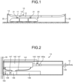
- FIG. 5 is a partial cross-sectional view of the configuration of a balancer according to the second modification of the first embodiment of the present invention.
- a balancer 14A according to the second modification further includes a laser distance sensor 200 and a reflecting plate 201.
- the configurations of the laser distance sensor 200 and the reflecting plate 201 will be described. Note that the same constituents as those in the first embodiment described above are given the same reference numerals.
- the laser distance sensor 200 is disposed in the outer surface of the hydraulic cylinder 142.
- the reflecting plate 201 is disposed to stand on the piston rod 143 so that the reflecting plate 201 can reflect laser light emitted by the laser distance sensor 200.
- the laser distance sensor 200 is configured to emit laser light toward the reflecting plate 201 and receive laser light reflected by the reflecting plate 201.
- the laser distance sensor 200 outputs, to the control unit 154, for example, information on the amount of time elapsed from the emission of laser light by the laser distance sensor 200 to the time the laser distance sensor 200 receives the laser light reflected by the reflecting plate 201, or information on a phase difference between the emitted light and the returned light.
- the control unit 154 is configured to determine the distance between the laser distance sensor 200 and the reflecting plate 201, based on information acquired from the laser distance sensor 200.
- the control unit 154 determines the position of the piston rod 143 in the hydraulic cylinder 142, based on the determined distance, the position of the laser distance sensor 200 in the hydraulic cylinder 142, and the position of the reflecting plate 201 in the piston rod 143.
- the piston rod 143 is controlled using the hydraulic pump 146, whereby the tension of the overhead wire 10 connected to the piston rod 143 is adjusted.
- a hydraulic tension-adjustment mechanism such as the hydraulic pump 146, the rate of change in tension can be reduced without increasing the number of members (for example, coil springs), and thus the rate of change in tension can be reduced while an increase in the size of the balancer can be substantially prevented.
- the position of the piston rod 143 is detected, based on laser light reflected by the reflecting plate 201, hence, the detection result actually depends on the position of the reflecting plate 201 corresponding to the moved position of the piston rod 143. Therefore, according to the position detection using the laser distance sensor 200 and the reflecting plate 201, the more accurate position of the piston rod 143 can be detected.
- a method for detecting the position of the piston rod 143 in the hydraulic cylinder 142 is not limited to the above-described distance measurement using the motor control and laser light, and any well-known method can be used.
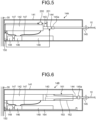
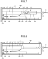
- FIG. 6 and FIG. 7 are partial cross-sectional views of the configuration of a balancer according to the third modification of the first embodiment of the present invention.
- a balancer 14B according to the third modification further includes a rust-preventing mechanism 161.
- the rust-preventing mechanism 161 will be described. Note that the same constituents as those in the first embodiment described above are given the same reference numerals.
- the rust-preventing mechanism 161 includes a hermetic case 162, an expansion member 163, and an oil pan 164.
- the hermetic case 162 is tubular in shape and has one end connected to the hydraulic cylinder 142, and allows the piston rod 143 to be inserted therethrough.
- the expansion member 163 is disposed inside the hermetic case 162. One end of the expansion member 163 is fixed to an inner wall of the hermetic case 162 and the other end of the expansion member 163 adheres to the tension sensor 144. Together with the inner wall of the hermetic case 162, the expansion member 163 forms a sealed space for sealing one end, on the tension sensor 144 side, of the piston rod 143. This sealed space is filled with an inert gas. Examples of inert gas include nitrogen and rare-gas elements.
- the oil pan 164 is configured to hold hydraulic oil leaking from the hydraulic cylinder 142 or the like.
- the expansion member 163 is configured to expand and contract in synchronization with the movement of the piston rod 143. For example, when the piston rod 143 is drawn into the hydraulic cylinder 142 (see FIG. 7 ) from the state where the tension sensor 144 is positioned outside the hermetic case 162 (see FIG. 6 ), the expansion member 163 contracts in synchronization with the movement of the piston rod 143. During this process, the hermetically sealed state between the expansion member 163 and the hermetic case 162 is maintained, and accordingly the piston rod 143 remains hermetically sealed in an inert gas atmosphere.
- the piston rod 143 is controlled using the hydraulic pump 146, whereby the tension of the overhead wire 10 connected to the piston rod 143 is adjusted.
- the rate of change in tension can be reduced without increasing the number of members (for example, coil springs), and thus the rate of change in tension can be reduced while an increase in the size of the balancer can be substantially prevented.
- the piston rod 143 is kept hermetically sealed in an inert gas atmosphere regardless of the movement of the piston rod 143, so that the formation of rust in the piston rod 143 can be substantially prevented.
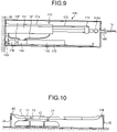
- FIG. 8 and FIG. 9 are partial cross-sectional views of the configuration of a balancer according to the fourth modification of the first embodiment of the present invention.
- a balancer 14C according to the fourth embodiment further includes a rust-preventing mechanism 171.
- the rust-preventing mechanism 171 will be described. Note that the same constituents as those in the first embodiment described above are given the same reference numerals.
- the rust-preventing mechanism 171 includes a wiper 172, a support member 173, a wiper-specific hydraulic cylinder 174, and an oil pan 175.
- Rust preventive oil is supplied to the wiper 172 via the wiper-specific hydraulic cylinder 174. Accordingly, the wiper 172 is covered with the rust-preventive oil.
- the rust preventive oil may be the above-described hydraulic oil or an oil selected in accordance with a material of the piston rod 143. Note that, in the case of supplying the hydraulic oil to the wiper 172, the hydraulic oil tank 149 may be shared or a tank other than the hydraulic oil tank 149 may be provided. In the case where a rust-preventive oil different from the hydraulic oil is supplied to the wiper 172, a tank other than the hydraulic oil tank 149 is provided.
- the support member 173 is configured to support the wiper 172 at one end thereof, and the other end of the support member 173 is accommodated in the wiper-specific hydraulic cylinder 174.
- the support member 173 is disposed so as to be freely movable forward and backward with respect to the wiper-specific hydraulic cylinder 174 under the control of the control unit 154.
- the oil pan 175 is configured to hold the hydraulic oil leaking from the wiper 172 or the like.
- the control unit 154 moves the support member 173 to put the wiper 172 into reciprocating motion between an end, on the hydraulic cylinder 142 side, of the piston rod 143 and the tension sensor 144.
- the hydraulic oil or a rust-preventive oil is applied to the surface of the piston rod 143.
- the control unit 154 may put the wiper 172 into the reciprocating motion at predetermined intervals or may put the wiper 172 into the reciprocating motion under the direction of the person in charge of management.
- the piston rod 143 is controlled using the hydraulic pump 146, whereby the tension of the overhead wire 10 connected to the piston rod 143 is adjusted.
- the rate of change in tension can be reduced without increasing the number of members (for example, coil springs), and thus, the rate of change in tension can be reduced while an increase in the size of the balancer can be substantially prevented.
- the piston rod 143 is kept covered with the hydraulic oil or the rust preventive oil, so that the formation of rust in the piston rod 143 can be substantially prevented.
- periodic rust preventive treatment is effective.
- the piston rod 143 sometimes moves, over one year, from a position with the minimum amount of travel to a position with the maximum amount of travel, for example, and accordingly the piston rod 143 is exposed to the open air for a long period, and therefore, the periodic rust preventive treatment is preferably performed.
- the wiper 172 may be moved by driving a rack and pinion with a motor.
- FIG. 10 is a diagram illustrating an exemplary aspect of balancers in use according to the second embodiment of the present invention.
- FIG. 10 is a diagram illustrating an exemplary aspect of balancers in use according to the second embodiment of the present invention.
- first embodiment an example in which one end of the overhead wire 10 is fixed to the support pole 30, and the balancer 14 is provided at the other end of the overhead wire 10 was described, however, in the second embodiment, balancers are respectively provided at both ends of the overhead wire 10. Note that the same constituents as those in the first embodiment described above are given the same reference numerals.
- one end of the overhead wire 10 is connected to the support pole 30 via a balancer 14D and the other end of the overhead wire 10 is connected to the support pole 30 via a balancer 14E.
- the tension of the overhead wire 10 is adjusted by the two balancers 14D and 14E.
- the balancers 14D and 14E are provided in the same overhead wire 10 targeted for tension adjustment and function as a pair of balancers.
- each of the balancers 14D and 14E includes the same constituents as those of the above-described balancer 14. Specifically, each of the balancers 14D and 14E includes the casing 141, the hydraulic cylinder 142, the piston rod 143, the tension sensor 144, the rod 145, the hydraulic pump 146, the hydraulic hose 147, the motor 148, the hydraulic oil tank 149, and the drive control unit 150.
- the control unit 154 of each of the balancers 14D and 14E is configured to control the piston rod 143, based on a calculated tension.
- the timing for controlling the piston rod 143 of the balancer 14D and the timing for controlling the piston rod 143 of the balancer 14E may be different or synchronized.
- the control of the piston rods 143 may be performed at the same time or at different times from each other.
- the drive control unit 150 of each of the balancers may change a set tension, based on a position of the piston rod 143 and a result of detection by the tension sensor 144.
- the drive control unit 150 changes the set tension by exercising control based on Hooke's law that the expansion of a spring is in proportional to a load equal to or lower than an elastic limit.
- Hooke's law that the expansion of a spring is in proportional to a load equal to or lower than an elastic limit.
- the balancers do not include a spring member (for example, a coil spring), and therefore, for example, even when the tension is controlled to an appropriate value, the amount of travel of one of the balancers is sometimes larger than the amount of travel of the other unless the amounts of travel of the piston rods 143 of both the balancers are controlled to the same level.
- a spring member for example, a coil spring
- the tension between the two balancers can be adjusted to be balanced without causing the balancers to communicate with each other for information, and furthermore, the positions (the amount of travel) of the piston rods 143 of the paired balancers (in this case, the balancers 14D and 14E) in the hydraulic cylinders 142 can be controlled to be relatively at the same level.
- the amounts of travel can be controlled to be at the same level.
- a constituent other than the hydraulic type such as an actuator using a chain or an actuator using a ball screw is adopted, for example, the rotational position of a motor can be used as information for control.
- the piston rod 143 is controlled using the hydraulic pump 146, whereby the tension of the overhead wire 10 connected to the piston rod 143 is adjusted.
- a hydraulic tension adjustment mechanism such as the hydraulic pump 146, the rate of change in tension can be reduced without increasing the number of members (for example, coil springs), and thus, the rate of change in tension can be reduced while an increase in the size of the balancer can be substantially prevented.
- the balancers are provided at both ends of the overhead wire 10, respectively, to adjust the tension at both ends of the overhead wire 10, so that a larger range of tension adjustment (the total amount of travel of the piston rods 143) can be secured.
- the balancers 14A to 14C according to the first and second modifications of the first embodiment may be used.
- FIG. 11 is a block diagram illustrating the configuration of a drive control unit in a balancer according to the first modification of the second embodiment.
- the above-described balancers 14D and 14E each include a drive control unit 150B, instead of the drive control unit 150.
- the drive control unit 150B will be described. Note that the same constituents as those in the first and second embodiments described above are given the same reference numerals.
- the drive control unit 150B includes the tension calculation unit 151, the tension determination unit 152, the driving amount calculation unit 153, the control unit 154, the memory 155, and a communication unit 157.
- the communication unit 157 of a balancer is configured to transmit and receive a control signal to and from another balancer paired with the balancer.
- the communication unit 157 of the balancer 14D is configured to transmit and receive a control signal to and from the communication unit 157 of the balancer 14E paired with the balancer 14D.
- the communication unit 157 may transmit and receive a signal by using the overhead wire 10 as a transmission path, or may transmit and receive a signal through wireless communications.
- the balancers 14D and 14E according to the first modification are configured to control the movement of the piston rods 143 in cooperation with each other.
- one of the balancers is set as a primary balancer and the other is set as a secondary balancer, and the primary balancer controls over the balancer paired with the primary balancer.
- the control unit 154 of the balancer 14D causes the tension calculation unit 151 and the tension determination unit 152 of the balancer 14E to perform tension determination. In this case, when tension is determined to be appropriate, the control unit 154 does not perform tension adjustment.
- the control unit 154 of the balancer 14E causes the tension calculation unit 151 and the tension determination unit 152 of the balancer 14E to perform tension determination, whereby the tension of balancer 14E, a result of the tension determination, and information on the position of the piston rod 143 are acquired.
- the driving amount calculation unit 153 of the balancer 14D sets the direction and amount of travel of the piston rod 143 of each of the balancers, based on the tension of each of the balancers, the determination result, and the position of the piston rod 143.
- the control unit 154 of the balancer 14D controls the piston rod 143 of the balancer 14D and transmits information on the control of the piston rod 143 to the balancer 14E via the communication unit 157. In this case, the piston rods 143 of the balancers 14D and 14E may be separately or synchronously moved.
- the piston rod 143 is controlled using the hydraulic pump 146, whereby the tension of the overhead wire 10 connected to the piston rod 143 is adjusted.
- a hydraulic tension-adjustment mechanism such as the hydraulic pump 146, the rate of change in tension can be reduced without increasing the number of members (for example, coil springs), and thus the rate of change in tension can be reduced while an increase in the size of the balancer can be substantially prevented.
- the balancers communicate with each other via the communication units 157 to control the piston rods 143 in accordance with tension, whereby a load on a single balancer can be reduced.
- the other balancer in this case, the balancer 14E may be configured not to include the driving amount calculation unit 153.
- the drive control unit of the balancer 14E includes the tension calculation unit 151, the tension determination unit 152, the control unit 154, the memory 155, and the communication unit 157.
- the tension determination unit 152 of the balancer 14D is configured to determine whether the tension of the balancer 14E is appropriate based on tension acquired from the balancer 14E
- the balancer 14E may be configured not to include the tension determination unit 152.
- the drive control unit of the balancer 14E includes the tension calculation unit 151, the control unit 154, the memory 155, and the communication unit 157.
- FIG. 12 is a block diagram illustrating the configuration of a drive control unit in a balancer according to the second modification of the second embodiment of the present invention.
- the above-described balancers 14D and 14E each include a drive control unit 150C, instead of the drive control unit 150.
- the drive control unit 150C will be described. Note that the same constituents as those in the first and second embodiments described above are given the same reference numerals.
- the drive control unit 150C includes the tension calculation unit 151, the tension determination unit 152, the driving amount calculation unit 153, the control unit 154, the memory 155, the overhead wire wear detection unit 156, the communication unit 157, and a global positioning system (GPS) unit 158.
- the balancer 14D includes a generator configured to generate vibration for wear detection.
- an actuator may be used as the vibration generator.
- the GPS unit 158 includes a receiver configured to receive radio waves from a GPS satellite.
- the GPS unit 158 is configured to acquire information on time, based on the received radio waves, and output the acquired information on time to the control unit 154.
- GNSS global navigation satellite system
- the GPS unit 158 acquires information on time at predetermined intervals or at set times.
- the control unit 154 re-sets the times, based on the acquired information on time.
- the control units 154 of the balancers can synchronize the times between the balancers.
- the control unit 154 of the balancer 14D when the balancer 14D is a primary balancer and the balancer 14E is a secondary balancer, the control unit 154 of the balancer 14D generates vibration for overhead wire wear detection and transmits the vibration to the balancer 14E via the overhead wire 10 (the catenary wire 11 or the trolley wire 12) to initiate overhead wire wear detection.
- the overhead wire wear detection unit 156 of the balancer 14D generates a vibration for wear detection for the balancer 14E.
- the vibration generated at this time is beneficially recognized by the balancer 14E, as a vibration for detecting the wear of the overhead wire 10.
- the balancer 14E When receiving the vibration for wear detection, the balancer 14E transmits a signal including the time of receipt of the vibration to the balancer 14D.
- the overhead wire wear detection unit 156 of the balancer 14D calculates the difference between the time of reception of the vibration and the time when the overhead wire wear detection unit 156 generates the vibration. This difference corresponds to a transmission time taken to transmit the vibration through the overhead wire 10 between the balancer 14D and the balancer 14E.
- the overhead wire wear detection unit 156 of the balancer 14D compares the calculated transmission time with a threshold value to detect the wear of the overhead wire 10.
- the threshold value mentioned herein is a value corresponding to the time of transmission through the unworn overhead wire 10 (the trolley wire 12), for example, a predetermined value or the time of transmission calculated immediately after the replacement of the overhead wire 10.
- the overhead wire wear detection unit 156 of the balancer 14D determines that the overhead wire 10 is worn.
- the overhead wire wear detection unit 156 of the balancer 14D outputs the determination result to the control unit 154.
- the control unit 154 When acquiring the determination result from the overhead wire wear detection unit 156, the control unit 154 stores the determination result in the memory 155 or transmits the determination result to a center configured to centrally control a plurality of the balancers. When transmitting the determination result to the center, the control unit 154 transmits information (for example, ID) for identifying the balancer 14D and the overhead wire 10 targeted for tension adjustment, together with the determination result.
- ID information
- the piston rod 143 is controlled using the hydraulic pump 146, whereby the tension of the overhead wire 10 connected to the piston rod 143 is adjusted.
- a hydraulic tension-adjustment mechanism such as the hydraulic pump 146, the rate of change in tension can be reduced without increasing the number of members (for example, coil springs), and thus the rate of change in tension can be reduced while an increase in the size of the balancer can be substantially prevented.
- the overhead wire wear detection unit 156 detects the wear of the overhead wire 10, based on the speed of transmission of vibration between the balancers 14D and 14E, whereby a person in charge of management can know the timing for the replacement of the overhead wire 10, for example.
- the secondary balancer in this case, the balancer 14E
- the drive control unit of the balancer 14E includes the tension calculation unit 151, the tension determination unit 152, the driving amount calculation unit 153, the control unit 154, the memory 155, the communication unit 157, and the GPS unit 158.
- the drive control unit may be configured not to include the GPS unit 158.
- the wear of the overhead wire 10 is detected by measuring the transmission speed (transmission time) of vibration
- a signal for wear detection is not limited to vibration.
- the expansion of the overhead wire 10 may be detected by measuring the propagation velocity of a sound wave.
- one balancer includes a generator configured to generate a sound
- another balancer includes a receiver configured to receive the sound generated by the generator.
- the drive control unit of each of the balancers includes, at least, the control unit 154, the memory 155, and the communication unit 157.
- the controller acquires a value detected by the tension sensor from each of the balancers, determines whether the tension is appropriate calculates the driving amount of each of the piston rods 143, and transmits the driving amount to each of the balancers.
- the controller controls each of the balancers by performing a part of the above-described balancer functions.
- the present invention may include various embodiments not described herein, and various design changes are allowed without departing from technical concepts specified by the scope of the claims.
- the examples in which the tension of a train wire is adjusted was described.
- the above-described balancers can be adopted for other targets for the adjustment of tension of a wire.
- the balancer and the balancer system according to the present invention are suitable for reducing the rate of change in tension while substantially preventing an increase in size.
Landscapes
- Engineering & Computer Science (AREA)
- Mechanical Engineering (AREA)
- Physics & Mathematics (AREA)
- Fluid Mechanics (AREA)
- General Engineering & Computer Science (AREA)
- Suspension Of Electric Lines Or Cables (AREA)
Applications Claiming Priority (2)
| Application Number | Priority Date | Filing Date | Title |
|---|---|---|---|
| JP2020063175A JP7391750B2 (ja) | 2020-03-31 | 2020-03-31 | バランサおよびバランサシステム |
| PCT/JP2021/009666 WO2021199999A1 (ja) | 2020-03-31 | 2021-03-10 | バランサおよびバランサシステム |
Publications (2)
| Publication Number | Publication Date |
|---|---|
| EP4131690A1 true EP4131690A1 (de) | 2023-02-08 |
| EP4131690A4 EP4131690A4 (de) | 2024-03-06 |
Family
ID=77928691
Family Applications (1)
| Application Number | Title | Priority Date | Filing Date |
|---|---|---|---|
| EP21781597.6A Withdrawn EP4131690A4 (de) | 2020-03-31 | 2021-03-10 | Ausgleichsvorrichtung und ausgleichssystem |
Country Status (4)
| Country | Link |
|---|---|
| EP (1) | EP4131690A4 (de) |
| JP (3) | JP7391750B2 (de) |
| KR (1) | KR20220146598A (de) |
| WO (1) | WO2021199999A1 (de) |
Families Citing this family (2)
| Publication number | Priority date | Publication date | Assignee | Title |
|---|---|---|---|---|
| JP7391750B2 (ja) * | 2020-03-31 | 2023-12-05 | 日本発條株式会社 | バランサおよびバランサシステム |
| JP2024113959A (ja) * | 2023-02-10 | 2024-08-23 | 日本発條株式会社 | テンションバランサ |
Family Cites Families (19)
| Publication number | Priority date | Publication date | Assignee | Title |
|---|---|---|---|---|
| JPS5034685U (de) * | 1973-07-27 | 1975-04-14 | ||
| JPS6069844U (ja) * | 1983-10-20 | 1985-05-17 | トキコ株式会社 | 減衰力調整式油圧緩衝器 |
| JPH07156699A (ja) * | 1993-12-07 | 1995-06-20 | East Japan Railway Co | 2重シリンダ式テンションバランサ |
| JPH08216739A (ja) * | 1994-12-14 | 1996-08-27 | Shinyoushiya:Kk | 架線長異常検出装置およびシステム |
| JPH08278215A (ja) * | 1995-03-31 | 1996-10-22 | Yaskawa Electric Corp | 架空電線の張力自動監視装置 |
| JPH08334421A (ja) * | 1995-06-06 | 1996-12-17 | Central Japan Railway Co | トロリ線の張力測定方法 |
| JP3666971B2 (ja) | 1996-01-31 | 2005-06-29 | 三和テッキ株式会社 | ばね式テンションバランサ |
| JPH09328025A (ja) * | 1996-06-11 | 1997-12-22 | Nagano Keiki Seisakusho Ltd | 架線の張力調節装置 |
| JP2000065118A (ja) * | 1998-08-25 | 2000-03-03 | Toyo Constr Co Ltd | 防錆型ダンパ及び船舶衝撃力吸収装置 |
| ITUD20010023A1 (it) * | 2001-02-09 | 2002-08-09 | Tesmec Spa | Procedimento di regolazione della tensione per macchine di tesatura e relativo apparato |
| JP2003074514A (ja) * | 2001-08-31 | 2003-03-12 | Hitachi Constr Mach Co Ltd | シリンダ装置 |
| JP3864775B2 (ja) * | 2001-12-13 | 2007-01-10 | 日立電線株式会社 | トロリ線の異常検出方法 |
| JP2008223797A (ja) * | 2007-03-08 | 2008-09-25 | Nhk Spring Co Ltd | ガススプリング |
| JP5203734B2 (ja) | 2008-02-01 | 2013-06-05 | 東海旅客鉄道株式会社 | 架空線用テンション装置 |
| JP2016165956A (ja) * | 2015-03-10 | 2016-09-15 | 株式会社日立製作所 | 磨耗判定システム |
| KR101775986B1 (ko) * | 2017-02-01 | 2017-09-07 | 김성찬 | 현수선 구조설비용 장력조절장치 |
| JP6869073B2 (ja) * | 2017-03-29 | 2021-05-12 | 三和テッキ株式会社 | 架空線の張力変化低減装置 |
| CN108728205B (zh) * | 2018-07-27 | 2021-05-11 | 南京科润工业介质股份有限公司 | 一种气相防锈油 |
| JP7391750B2 (ja) * | 2020-03-31 | 2023-12-05 | 日本発條株式会社 | バランサおよびバランサシステム |
-
2020
- 2020-03-31 JP JP2020063175A patent/JP7391750B2/ja active Active
-
2021
- 2021-03-10 WO PCT/JP2021/009666 patent/WO2021199999A1/ja not_active Ceased
- 2021-03-10 KR KR1020227033550A patent/KR20220146598A/ko not_active Ceased
- 2021-03-10 EP EP21781597.6A patent/EP4131690A4/de not_active Withdrawn
-
2023
- 2023-11-22 JP JP2023198395A patent/JP2024009213A/ja active Pending
- 2023-11-22 JP JP2023198394A patent/JP2024009212A/ja active Pending
Also Published As
| Publication number | Publication date |
|---|---|
| WO2021199999A1 (ja) | 2021-10-07 |
| EP4131690A4 (de) | 2024-03-06 |
| JP2024009212A (ja) | 2024-01-19 |
| JP2024009213A (ja) | 2024-01-19 |
| JP2021160501A (ja) | 2021-10-11 |
| KR20220146598A (ko) | 2022-11-01 |
| JP7391750B2 (ja) | 2023-12-05 |
Similar Documents
| Publication | Publication Date | Title |
|---|---|---|
| EP4131690A1 (de) | Ausgleichsvorrichtung und ausgleichssystem | |
| EP1564440B1 (de) | Treibriemensystem mit automatischem Riemenspannungskontrol | |
| CN110786971B (zh) | 假体部件或外骨骼部件以及操作它们的方法 | |
| US9988217B2 (en) | Conveyor belt wear monitoring system | |
| US20160040995A1 (en) | Device for predicting energy consumption and method for predicting energy consumption | |
| US20120232793A1 (en) | Navigation system and on-vehicle device | |
| US11807495B2 (en) | Measuring device for measuring an elevator shaft and use of the measuring device to measure an elevator shaft | |
| WO1998047758A3 (de) | Anker-/ankerketten-überwachungsvorrichtung | |
| US7324894B2 (en) | Attitude detection method and apparatus for initial motion control | |
| FR3052654B1 (fr) | Procede d'estimation de l'orientation relative entre tibia et femur | |
| BR0300432B1 (pt) | instalação para amortização de oscilações para uma cabina de elevador. | |
| KR101943036B1 (ko) | 부유식 차집관로 검사 장치 | |
| US12006646B2 (en) | Fender | |
| Zhe et al. | A new method of predicting the occurrence of contact loss between pairing elements in planar linkages with clearances | |
| KR102114980B1 (ko) | 자세제어유닛을 포함하는 수중구조물 형상측정장치 | |
| WO1996006264A1 (en) | Method and apparatus for steering a drill head | |
| US11858744B2 (en) | Conveyor with clamping connection and method for operating a conveyor | |
| EP2015098A3 (de) | Verfahren zur Bestimmung eines Steuerungsfehlers in einer Abtastschleife mit einem Pseudo-Zufallscode | |
| CN115290453A (zh) | 一种钢筋延伸率测量装置及其测量方法 | |
| CN114833804A (zh) | 一种适用于多场景的有源助力装置及方法 | |
| RU2815431C1 (ru) | Пневмогравитационная транспортная секция | |
| AU2015215240B2 (en) | Device and method for longwall installation course determination | |
| CN113602926B (zh) | 具有基于电梯轿厢位置的变化无线传输功率的电梯监测装置 | |
| WO2019053471A1 (en) | ALIGNMENT FAULT DETECTION | |
| RU2002131975A (ru) | Способ определения положения центра тяжести лопатки турбины |
Legal Events
| Date | Code | Title | Description |
|---|---|---|---|
| STAA | Information on the status of an ep patent application or granted ep patent |
Free format text: STATUS: THE INTERNATIONAL PUBLICATION HAS BEEN MADE |
|
| PUAI | Public reference made under article 153(3) epc to a published international application that has entered the european phase |
Free format text: ORIGINAL CODE: 0009012 |
|
| STAA | Information on the status of an ep patent application or granted ep patent |
Free format text: STATUS: REQUEST FOR EXAMINATION WAS MADE |
|
| 17P | Request for examination filed |
Effective date: 20220928 |
|
| AK | Designated contracting states |
Kind code of ref document: A1 Designated state(s): AL AT BE BG CH CY CZ DE DK EE ES FI FR GB GR HR HU IE IS IT LI LT LU LV MC MK MT NL NO PL PT RO RS SE SI SK SM TR |
|
| DAV | Request for validation of the european patent (deleted) | ||
| DAX | Request for extension of the european patent (deleted) | ||
| REG | Reference to a national code |
Ref country code: DE Ref legal event code: R079 Free format text: PREVIOUS MAIN CLASS: H02G0007020000 Ipc: B60M0001260000 |
|
| RIC1 | Information provided on ipc code assigned before grant |
Ipc: H02G 7/02 20060101ALI20230801BHEP Ipc: B60M 1/26 20060101AFI20230801BHEP |
|
| A4 | Supplementary search report drawn up and despatched |
Effective date: 20240201 |
|
| RIC1 | Information provided on ipc code assigned before grant |
Ipc: H02G 7/02 20060101ALI20240126BHEP Ipc: B60M 1/26 20060101AFI20240126BHEP |
|
| STAA | Information on the status of an ep patent application or granted ep patent |
Free format text: STATUS: THE APPLICATION IS DEEMED TO BE WITHDRAWN |
|
| 18D | Application deemed to be withdrawn |
Effective date: 20240821 |