EP4132315B1 - Partie de fermeture - Google Patents
Partie de fermeture Download PDFInfo
- Publication number
- EP4132315B1 EP4132315B1 EP21815492.0A EP21815492A EP4132315B1 EP 4132315 B1 EP4132315 B1 EP 4132315B1 EP 21815492 A EP21815492 A EP 21815492A EP 4132315 B1 EP4132315 B1 EP 4132315B1
- Authority
- EP
- European Patent Office
- Prior art keywords
- crater
- fastener
- depression
- head
- curvature
- Prior art date
- Legal status (The legal status is an assumption and is not a legal conclusion. Google has not performed a legal analysis and makes no representation as to the accuracy of the status listed.)
- Active
Links
Images

Classifications
-
- A—HUMAN NECESSITIES
- A44—HABERDASHERY; JEWELLERY
- A44B—BUTTONS, PINS, BUCKLES, SLIDE FASTENERS, OR THE LIKE
- A44B18/00—Fasteners of the touch-and-close type; Making such fasteners
- A44B18/0046—Fasteners made integrally of plastics
- A44B18/0061—Male or hook elements
- A44B18/0065—Male or hook elements of a mushroom type
-
- A—HUMAN NECESSITIES
- A44—HABERDASHERY; JEWELLERY
- A44B—BUTTONS, PINS, BUCKLES, SLIDE FASTENERS, OR THE LIKE
- A44B18/00—Fasteners of the touch-and-close type; Making such fasteners
- A44B18/0046—Fasteners made integrally of plastics
- A44B18/0049—Fasteners made integrally of plastics obtained by moulding processes
-
- A—HUMAN NECESSITIES
- A44—HABERDASHERY; JEWELLERY
- A44B—BUTTONS, PINS, BUCKLES, SLIDE FASTENERS, OR THE LIKE
- A44B18/00—Fasteners of the touch-and-close type; Making such fasteners
- A44B18/0003—Fastener constructions
- A44B18/0015—Male or hook elements
- A44B18/0019—Male or hook elements of a mushroom type
-
- B—PERFORMING OPERATIONS; TRANSPORTING
- B29—WORKING OF PLASTICS; WORKING OF SUBSTANCES IN A PLASTIC STATE IN GENERAL
- B29C—SHAPING OR JOINING OF PLASTICS; SHAPING OF MATERIAL IN A PLASTIC STATE, NOT OTHERWISE PROVIDED FOR; AFTER-TREATMENT OF THE SHAPED PRODUCTS, e.g. REPAIRING
- B29C43/00—Compression moulding, i.e. applying external pressure to flow the moulding material; Apparatus therefor
- B29C43/22—Compression moulding, i.e. applying external pressure to flow the moulding material; Apparatus therefor of articles of indefinite length
- B29C43/222—Compression moulding, i.e. applying external pressure to flow the moulding material; Apparatus therefor of articles of indefinite length characterised by the shape of the surface
-
- B—PERFORMING OPERATIONS; TRANSPORTING
- B29—WORKING OF PLASTICS; WORKING OF SUBSTANCES IN A PLASTIC STATE IN GENERAL
- B29C—SHAPING OR JOINING OF PLASTICS; SHAPING OF MATERIAL IN A PLASTIC STATE, NOT OTHERWISE PROVIDED FOR; AFTER-TREATMENT OF THE SHAPED PRODUCTS, e.g. REPAIRING
- B29C43/00—Compression moulding, i.e. applying external pressure to flow the moulding material; Apparatus therefor
- B29C43/32—Component parts, details or accessories; Auxiliary operations
- B29C43/44—Compression means for making articles of indefinite length
- B29C43/46—Rollers
-
- B—PERFORMING OPERATIONS; TRANSPORTING
- B29—WORKING OF PLASTICS; WORKING OF SUBSTANCES IN A PLASTIC STATE IN GENERAL
- B29C—SHAPING OR JOINING OF PLASTICS; SHAPING OF MATERIAL IN A PLASTIC STATE, NOT OTHERWISE PROVIDED FOR; AFTER-TREATMENT OF THE SHAPED PRODUCTS, e.g. REPAIRING
- B29C43/00—Compression moulding, i.e. applying external pressure to flow the moulding material; Apparatus therefor
- B29C43/32—Component parts, details or accessories; Auxiliary operations
- B29C43/44—Compression means for making articles of indefinite length
- B29C43/46—Rollers
- B29C2043/461—Rollers the rollers having specific surface features
-
- B—PERFORMING OPERATIONS; TRANSPORTING
- B29—WORKING OF PLASTICS; WORKING OF SUBSTANCES IN A PLASTIC STATE IN GENERAL
- B29C—SHAPING OR JOINING OF PLASTICS; SHAPING OF MATERIAL IN A PLASTIC STATE, NOT OTHERWISE PROVIDED FOR; AFTER-TREATMENT OF THE SHAPED PRODUCTS, e.g. REPAIRING
- B29C48/00—Extrusion moulding, i.e. expressing the moulding material through a die or nozzle which imparts the desired form; Apparatus therefor
- B29C48/001—Combinations of extrusion moulding with other shaping operations
- B29C48/0011—Combinations of extrusion moulding with other shaping operations combined with compression moulding
-
- B—PERFORMING OPERATIONS; TRANSPORTING
- B29—WORKING OF PLASTICS; WORKING OF SUBSTANCES IN A PLASTIC STATE IN GENERAL
- B29C—SHAPING OR JOINING OF PLASTICS; SHAPING OF MATERIAL IN A PLASTIC STATE, NOT OTHERWISE PROVIDED FOR; AFTER-TREATMENT OF THE SHAPED PRODUCTS, e.g. REPAIRING
- B29C48/00—Extrusion moulding, i.e. expressing the moulding material through a die or nozzle which imparts the desired form; Apparatus therefor
- B29C48/03—Extrusion moulding, i.e. expressing the moulding material through a die or nozzle which imparts the desired form; Apparatus therefor characterised by the shape of the extruded material at extrusion
- B29C48/07—Flat, e.g. panels
-
- B—PERFORMING OPERATIONS; TRANSPORTING
- B29—WORKING OF PLASTICS; WORKING OF SUBSTANCES IN A PLASTIC STATE IN GENERAL
- B29C—SHAPING OR JOINING OF PLASTICS; SHAPING OF MATERIAL IN A PLASTIC STATE, NOT OTHERWISE PROVIDED FOR; AFTER-TREATMENT OF THE SHAPED PRODUCTS, e.g. REPAIRING
- B29C48/00—Extrusion moulding, i.e. expressing the moulding material through a die or nozzle which imparts the desired form; Apparatus therefor
- B29C48/03—Extrusion moulding, i.e. expressing the moulding material through a die or nozzle which imparts the desired form; Apparatus therefor characterised by the shape of the extruded material at extrusion
- B29C48/13—Articles with a cross-section varying in the longitudinal direction, e.g. corrugated pipes
-
- B—PERFORMING OPERATIONS; TRANSPORTING
- B29—WORKING OF PLASTICS; WORKING OF SUBSTANCES IN A PLASTIC STATE IN GENERAL
- B29L—INDEXING SCHEME ASSOCIATED WITH SUBCLASS B29C, RELATING TO PARTICULAR ARTICLES
- B29L2031/00—Other particular articles
- B29L2031/727—Fastening elements
- B29L2031/729—Hook and loop-type fasteners
Definitions
- the invention relates to a closure part consisting of at least one flat carrier part, on one side of which a plurality of mushroom-head-like closure elements are arranged according to the feature design of the preamble of patent claim 1.
- the known adhesive fastener part is provided with a plurality of symmetrically constructed hooking means connected in one piece to a carrier in the form of a stem part each provided with a head part, wherein a moldable material is fed into a molding zone between a pressure tool and a molding tool to carry out the manufacturing process.
- a moldable material is fed into a molding zone between a pressure tool and a molding tool to carry out the manufacturing process.
- the invention is based on the object of further improving the known solutions in such a way that a closure part with greater functionality and expanded areas of application is created.
- a closure part with the features of patent claim 1 in its entirety solves this problem. Due to the fact that, according to the characterizing part of patent claim 1, a large number of further crater-like depressions are introduced on the other side of the carrier part opposite the closure elements, that the two crater-like depressions run concentrically or essentially concentrically to the longitudinal axis of the respectively associated stem part at least in some of the closure elements, and that the respective further crater-like depression has a maximum crater depth that is between 30-60%, preferably 50%, of the thickness of the carrier part, an additional functionality is created compared to the otherwise flat sides of the carrier part, which also leads to expanded areas of application for such closure parts.
- the further crater-like depressions in the rear area of the carrier part lead to a significant reduction in weight, whereby grammages (mass/area unit in g/m 2 ) in the order of magnitude of normal paper for copiers and printers can be achieved; i.e. values of ⁇ 80g/m 2 .
- closure parts of the type in question are mass-produced goods and have to be sent to their respective locations (automotive industry, diaper industry, clothing industry, etc.) as roll goods measuring thousands of square metres, this allows save transport costs to a significant extent without affecting the technical properties of such fasteners, which consist of forming a reusable fastener with a loop or looped material from a third-party component, which is also known in technical terms as a Velcro fastener, even among end users.
- the additional crater-like depressions in the carrier part mentioned above not only serve to reduce weight, but overall less plastic material is required to produce a closure part using known manufacturing processes (chill-roll process), which helps to save costs and reduces the burden on the environment.
- the respective additional crater-like depressions also provide the possibility of forming collection spaces or reservoirs, for example for the absorption of adhesives that are required to be able to attach the respective closure part to a third-party component at a later date at its place of use.
- the closure part always had to be more or less completely covered with an adhesive layer on the back of the carrier part. This increases the amount of adhesive required and therefore the overall product costs, and it can also lead to unwanted detachment of the adhesive coating, which is avoided with the present solution according to the invention, since the adhesive is largely protected by the respective further crater-like depression.
- the respective further crater-like depression has a maximum crater depth that is between 30 and 60%, preferably 50% of the thickness of the carrier part.
- a maximum crater depth that is between 30 and 60%, preferably 50% of the thickness of the carrier part.
- each closure element there is a recess associated with each closure element and that all closure elements are designed the same, as are all recesses to one another. In this way, a regular structure is achieved for the respective closure part as a whole, with extensive symmetry along the longitudinal and transverse axes of the closure part.
- the functionality of the new generation of closure parts mentioned above is increased, as are the possible areas of application for closure parts designed in this way with crater- or dent-like depressions on the back.
- the additional crater-like depressions can easily be introduced into the carrier part mechanically from the outside, for example by allowing the projections arranged on an additional forming roller to penetrate into the rear area of the still plasticized carrier part in order to introduce the additional crater-like depressions into the plastic material and compact it.
- Another manufacturing option is to displace the material in the rear area of the carrier part by applying a fluid at high pressure (water, air, etc.) through a nozzle, while simultaneously producing the depressions mentioned.
- the manufacturing processes used in this way ultimately do not result in a reduction in the grammage for the respective closure part, since the plastic material is basically only displaced and not removed from the closure part itself.
- etching processes such as those used in micro-electroplating, to remove the plastic material from the back of the carrier part in order to create the respective additional crater-like depression. By removing the plastic material, the grammage of the closure part is then reduced.
- the respective further crater-like depression starting from the flat, further side of the carrier part, runs continuously from there to the crater base without any protrusion. Since no protruding crater edge is created during the manufacture of the closure part, the further processing of the closure part is not impaired.
- the respective further crater-like depression transitions from a convex to a concave curvature in the direction of the crater base starting from the further side of the carrier part.
- the respective further crater-like depression viewed in a longitudinal direction of the carrier part which corresponds to the direction of production, again viewed in longitudinal cross-section, runs out more flatly on one side in the direction of the further side of the carrier part than on the opposite cross-sectional side.
- the crater formation in this regard arises during the demolding process for the respective closure element from the molding roller, which benefits the hindrance-free demolding process.
- the respective stem part of a closure element forms the uniformly extending rotation body at least at its base-side transition point to the carrier part, which has a smaller curvature than the transition of the stem part to the head-side widening with the hooking points of the closure element and that the curvature at each point of the adjacent opposite depressions has a smaller curvature than the curvature relating to the head-side curvature of the stem part.
- the largest diameter of the further crater-like depression at the point of the outlet to the further side of the carrier part is larger than the diameter of the stem part at any point between its foot and its head side, preferably larger than the extension of the head part at its widest point.
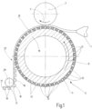
- Fig.1 shows a schematic representation of parts of a device for carrying out a manufacturing process for obtaining a closure part according to the invention.
- the device has an extruder head 1 as a feed device for plastic or liquid plastic, in particular thermoplastic, which is in the form of a band, the width of which that of the fastener part or the adhesive fastener part to be produced, is fed into the gap between a pressure tool and a forming tool.
- a pressure roller 3 is provided as the pressure tool, while the forming tool is a forming roller designated as a whole by 5.
- Both rollers are in the Fig.1 driven in the directions of rotation indicated by arrows 7 and 9, so that a conveying gap is formed between them, through which the plastic strip is conveyed in the transport direction, while at the same time in the gap as a shaping zone the plastic strip is shaped into the carrier part 10 of the closure part and the carrier part 10 is given the shape required to form closure elements on the side adjacent to the shaping roller 5 by the shaping elements of the shaping roller 5.
- the forming roller 5 has a screen 11 with individual mold cavities 12 on its circumference.
- a mold cavity 12 is shown by way of example in the Fig.2 shown enlarged.
- the mold cavities 12, which is not shown in more detail, are evenly distributed over the outer circumference of the mold roller 5 with its screen 11, whereby the distribution and the number can be freely selected.
- the Fig.2 shows a longitudinal section through the mold cavity 12 used in each case, wherein the boundary walls 13 opposite in the longitudinal section are provided with a convex path 14 throughout. It is understood that the two boundary walls 13 mentioned are, in view of the rotationally symmetrical structure of the mold cavity 12, basically only part of a final molding wall 15 which is limited by the screen material 11 of the molding roller 5. With the mold cavities 12 in question, it is in any case possible to produce closure elements in the form of a stem part 17 provided with a head part 16, wherein the head part 16, stem part 17 and opposite carrier part 10 merge into one another in one piece.
- Fig.1 The molding device shown thus allows the closure part according to the invention to be manufactured within the framework of a type of casting or extrusion process, which in technical terms is also referred to as a chill-roll manufacturing process.
- the curvature of the respective path 14 in the direction of the head part 16 to be formed in the direction of the Fig.2 seen, upper area) than in the direction of a foot part 18, via which the stem part 17 is connected to the support part 10 on the foot or bottom side. It has proven to be particularly advantageous, also for the molding of the closure part to be produced from the molding device, if the path 14 with its stronger curvature is provided above the middle, preferably starting in the upper third, as seen from the longitudinal direction of the stem part 17 in the direction of the head part 16.
- the mentioned mold cavities 12 with their rotationally symmetrical structure in the form of a hyperboloid, galvanic coating processes have proven to be effective, in which a cylindrical mold cavity (not shown) is first coated with a coating material until the convex path 14 is established.
- the convex path 14 could also be produced from a solid screen or grid material using a laser or etching process.
- the Fig.3 The individual closure element shown, of which a plurality is located on an upper side of the carrier part 10, can be produced using the method described above, including the manufacturing device according to the Fig.1
- the symmetrical structure results directly from the production in a mold cavity 12 after the Fig.2 .
- the closure element in question can be geometrically very small, for example only 0.4 mm high, with a Width of the closure head 16 in the order of 0.6 mm.
- the cross section of the stem part 17 in this embodiment is approximately 0.25 mm.
- the thickness of the carrier part 10 can be made even smaller, for example with a thickness between 0.05 mm and 2 mm.
- the above-mentioned dimensions are only to be regarded as working examples; of course, it is also possible to realize other size ratios.
- a large number of such closure elements can be arranged on the carrier part 10.
- the hexagonal head shape of the head part 16, which is present in plan view, does not need to be further processed.
- other head geometries can also be easily achieved using the described shaping process. Since the screen 11 is supported on a solid forming roller body 19, an air inclusion takes place between the respective head top and the outer peripheral side of the roller body 19, with the result that the air is displaced towards the middle of the head top and there forms a crater-like, convex recess or depression 20 when viewed from the outside, which contributes to increasing the rigidity towards the edges of the head part 16.
- the edge of the respective head part 16 protrudes over the stem part 17 at the edge and thus forms a circumferential hooking option 21 for the engagement of a head or loop material (not shown) of a corresponding closure part in order to create a hook and loop fastener (Velcro fastener) that can be opened and closed again. If necessary, other head geometries can also be realized.
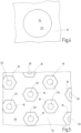
- a further crater-like depression 23 is provided, which in a view of the carrier part 10 from below in the Fig.4 is reproduced as an example. It is understood that in the In view of the large number of closure elements standing on the carrier part 10, a corresponding number of further crater-like depressions 23 are also present in the carrier part 10. Otherwise, the upper side 26 and the lower side 22 of the carrier part 10 run plane-parallel to one another.
- the respective further crater-like depression 23 runs, starting from the flat further side 22 of the carrier part 10, from there without protrusion, continuously to the crater base 24.
- the respective further depression 23 extends in a longitudinal section according to the illustration after the Fig.3 viewed from the other side 22 of the carrier part 10, the curvature changes from a convex to a concave curvature in the direction of the crater base 24. It has proven to be advantageous in terms of manufacturing technology if the concave curvature in the area of the crater base 24 is less curved than the convex curve. However, other path and curvature curves can also be selected depending on the process requirements, whereby in the present case the curvature curve is viewed from the inside of the carrier part 10.
- the respective further depression 23 has a maximum crater depth which is between 30 and 60%, preferably about 50%, of the thickness of the carrier part 10.
- the respective further crater-like depression 23 with its crater base 24 and with its other crater course up to the crater rim is essentially concentric with the stem part 17 of the respective mushroom-head-like formed closure element which, as already explained, is connected in one piece to the carrier part 10 adjacent to and opposite this further recess 23 with a predeterminable amount of projection therefrom.
- each closure element is provided with such a further crater-like depression 23, whereby all closure elements are preferably designed in the same way, as are all further crater-like depressions 23 to one another.
- This also applies accordingly to the head-side convex recess 20 on the top side of the respective head part 16 of a closure element.
- the respective stem part 17 of a closure element forms a uniformly extending rotational body at least at its base-side transition point in the form of the base part 18 towards the carrier part 10, wherein the transition point 18 has a smaller curvature than the transition of the stem part 17 to the head-side widening with the hooking points 21 of the closure element.
- the curvature of the stem part 17 preferably has a smaller curvature at each point of the adjacent, opposite, further crater-like depressions 23 than the curvature relating to the head-side curvature of the stem part 17, in order to achieve a particularly high hooking strength for the closure part according to the invention.
- the largest diameter of the further crater-like depression 23 at the point of the outlet to the further side 22 of the carrier part 10 is larger than the diameter of the stem part at any point between its foot 18 and its head side 16, preferably the diameter of the further crater-like depression 23 is larger than the extent of the head part 16 at its widest point (not shown).
- the plastics used for the closure part are preferably those with an elongation at break of more than 30% and the size and thickness dimensions given above are preferably measured with a DM2000 thickness gauge from Wolff-Messtechnik.
- biodegradable materials can also be used, which can preferably be produced on the basis of renewable or petrochemical raw materials or from combinations of both.
- Another possibility for introducing the further crater- or dent-like depressions 23 is to use either the pressure roller 3 and/or a demoulding roller 28 (see Fig.1 ) with projections (not shown) on the outer circumference, which correspond to the contour of the further crater-like depression 23 to be incorporated and which are then transferred via the rollers 3, 28 to the back of the carrier part 10.
- the respective further crater-like depression 23 can also be introduced in the carrier part 10 at a location other than in the extension of the stem part 17.
- embossed depressions can also be combined with the further crater-like depressions 23, as they arise when the closure part is pulled out of the mold cavities of the mold roller 5 as described.
Landscapes
- Engineering & Computer Science (AREA)
- Mechanical Engineering (AREA)
- Slide Fasteners, Snap Fasteners, And Hook Fasteners (AREA)
Claims (9)
- Partie de fermeture constituée d'au moins une pièce de support (10) de réalisation aplatie, sur l'une des faces de laquelle est implantée une pluralité d'éléments obturateurs du type tête de champignon respectivement munis, en tant que composant monobloc de ladite pièce de support (10), d'une pièce massive (17) formant fût, conçue à la manière d'un hyperboloïde de révolution, s'étendant le long d'un axe longitudinal, et à l'extrémité libre de laquelle se rattache une pièce (16) formant tête qui fait au moins partiellement saillie au-delà de ladite pièce (17) formant fût, par ses régions marginales conférant des facultés d'accrochage, et est dotée d'un renfoncement (20) du type cratère sur sa face supérieure,
caractérisée par le fait qu'une pluralité de renfoncements supplémentaires (23) du type cratère est façonnée sur l'autre face (22) de la pièce de support (10), tournée à l'opposé des éléments obturateurs ; par le fait que les deux renfoncements (20, 23) du type cratère s'étendent, concernant au moins une partie desdits éléments obturateurs, concentriquement ou pour l'essentiel concentriquement à l'axe longitudinal de la pièce (17) formant fût, respectivement associée ; et par le fait que le renfoncement supplémentaire (23) considéré, du type cratère, présente une profondeur maximale comprise entre 30-60 %, préférentiellement de l'ordre de 50 % de l'épaisseur de ladite pièce de support (10). - Partie de fermeture selon la revendication 1, caractérisée par le fait que le renfoncement supplémentaire (23) considéré, du type cratère, s'étend de manière continue jusqu'au fond (24) du cratère à partir de l'autre face (22) de la pièce de support (10) à étendue plane, sans débord au-delà de cette dernière.
- Partie de fermeture selon la revendication 1 ou 2, caractérisée par le fait que, virtuellement observé en coupe longitudinale, le renfoncement supplémentaire (23) considéré, du type cratère, fusionne d'un profil à courbure convexe à un profil à courbure concave, en direction du fond (24) du cratère, à partir de l'autre face (22) de la pièce de support (10).
- Partie de fermeture selon l'une des revendications précédentes, caractérisée par le fait que le profil à courbure concave présente une courbure moins accentuée que celle du profil convexe.
- Partie de fermeture selon l'une des revendications précédentes, caractérisée par le fait que, lorsqu'il est observé dans la direction longitudinale (25) de la pièce de support (10) correspondant à la direction de fabrication, le renfoncement supplémentaire (23) considéré du type cratère, observé de nouveau en coupe longitudinale, s'achève d'un côté, en direction de l'autre face (22) de la pièce de support (10), d'une manière plus aplatie que du côté opposé en coupe transversale.
- Partie de fermeture selon l'une des revendications précédentes, caractérisée par la présence d'un renfoncement supplémentaire (23) du type cratère, associé à chaque élément obturateur ; et par le fait que tous les éléments obturateurs sont de réalisation identique, de même que tous les renfoncements supplémentaires (23) du type cratère, les uns par rapport aux autres.
- Partie de fermeture selon l'une des revendications précédentes, caractérisée par le fait que la pièce respective (17) formant fût d'un élément obturateur matérialise, au moins au niveau de sa zone de base (18) procurant transition avec la pièce de support (10), le corps de révolution au tracé uniforme qui présente une courbure moindre que celle de la transition de ladite pièce (17) formant fût avec l'élargissement (16) situé côté tête et pourvu des zones d'accrochage (21) ; et par le fait que le profil de courbure présente, au niveau de chaque zone des renfoncements supplémentaires (23) du type cratère occupant des emplacements voisins opposés, une courbure moindre que la courbure relative au profil de courbure situé côté tête de ladite pièce (17) formant fût.
- Partie de fermeture selon l'une des revendications précédentes, caractérisée par le fait que le diamètre maximal du renfoncement supplémentaire (23) du type cratère présente, au niveau de la zone d'achèvement gagnant l'autre face (22) de la pièce de support (10), un dimensionnement supérieur à celui du diamètre de la pièce (17) formant fût, au niveau de chaque zone située entre le côté de sa base (18) et son côté tête (16), de préférence supérieur à l'étendue dudit côté tête (16) au niveau de sa zone la plus large.
- Partie de fermeture selon l'une des revendications précédentes, caractérisée par le fait qu'un agent adhésif est intégré dans le renfoncement supplémentaire (23) du type cratère.
Applications Claiming Priority (2)
| Application Number | Priority Date | Filing Date | Title |
|---|---|---|---|
| DE102020007585.1A DE102020007585A1 (de) | 2020-12-11 | 2020-12-11 | Verschlussteil |
| PCT/EP2021/082285 WO2022122345A1 (fr) | 2020-12-11 | 2021-11-19 | Partie de fermeture |
Publications (3)
| Publication Number | Publication Date |
|---|---|
| EP4132315A1 EP4132315A1 (fr) | 2023-02-15 |
| EP4132315C0 EP4132315C0 (fr) | 2024-05-15 |
| EP4132315B1 true EP4132315B1 (fr) | 2024-05-15 |
Family
ID=78806525
Family Applications (1)
| Application Number | Title | Priority Date | Filing Date |
|---|---|---|---|
| EP21815492.0A Active EP4132315B1 (fr) | 2020-12-11 | 2021-11-19 | Partie de fermeture |
Country Status (8)
| Country | Link |
|---|---|
| US (1) | US20230320464A1 (fr) |
| EP (1) | EP4132315B1 (fr) |
| JP (1) | JP7539741B2 (fr) |
| CN (1) | CN116249609B (fr) |
| DE (1) | DE102020007585A1 (fr) |
| ES (1) | ES2983440T3 (fr) |
| TW (1) | TWI858301B (fr) |
| WO (1) | WO2022122345A1 (fr) |
Families Citing this family (1)
| Publication number | Priority date | Publication date | Assignee | Title |
|---|---|---|---|---|
| DE102022131979A1 (de) | 2022-12-02 | 2024-06-13 | Lohmann-Koester Gmbh & Co. Kg | Hakenbandmaterial sowie Hakenbandmaterialrolle und -spule |
Family Cites Families (24)
| Publication number | Priority date | Publication date | Assignee | Title |
|---|---|---|---|---|
| ES453167A1 (es) * | 1976-11-10 | 1977-11-16 | Velero Espanola S A | Mejoras en los procedimientos de fabricacion continua de e- lementos monobloques autofijables. |
| US5845375A (en) * | 1990-09-21 | 1998-12-08 | Minnesota Mining And Manufacturing Company | Mushroom-type hook strip for a mechanical fastener |
| US5212853A (en) | 1992-03-10 | 1993-05-25 | Nifco Inc. | Separable plastic fastener and method and apparatus for manufacturing thereof |
| JPH09238714A (ja) * | 1996-03-04 | 1997-09-16 | Ykk Corp | 合成樹脂製の一体成形面ファスナー |
| DE19646318A1 (de) | 1996-11-09 | 1998-05-14 | Binder Gottlieb Gmbh & Co | Rationelles Verfahren zur Herstellung eines Haftverschlußteils aus thermoplatischem Kunststoff |
| JPH11181261A (ja) * | 1997-12-25 | 1999-07-06 | Ykk Corp | 生分解性樹脂成形品 |
| DE19828856C1 (de) * | 1998-06-29 | 1999-10-07 | Binder Gottlieb Gmbh & Co | Verfahren zur Herstellung eines Haftverschlußteiles |
| DE10039937A1 (de) | 2000-08-16 | 2002-03-07 | Binder Gottlieb Gmbh & Co | Verfahren zum Herstellen eines Haftverschlußteils |
| US7246416B2 (en) | 2000-10-19 | 2007-07-24 | Leonard Arnold Duffy | Slidingly Engagable Fasteners and method |
| JP3818431B2 (ja) * | 2001-03-08 | 2006-09-06 | Ykk株式会社 | 一体成形面ファスナーとその連続製造方法及び連続製造装置 |
| DE10123205A1 (de) * | 2001-05-12 | 2002-11-28 | Binder Gottlieb Gmbh & Co | Verfahren zur Herstellung eines Haftverschlußteils |
| JP3847297B2 (ja) * | 2003-12-25 | 2006-11-22 | Ykk株式会社 | 面ファスナーの連続成形方法と成形装置 |
| DE102004058257B4 (de) * | 2004-12-03 | 2007-05-16 | Binder Gottlieb Gmbh & Co Kg | Verfahren zum Herstellen einer Trägerbahn sowie Trägerbahn |
| US7516524B2 (en) * | 2005-03-11 | 2009-04-14 | Velcro Industries B.V. | Hook fastener components and methods of their manufacture |
| US20080134476A1 (en) * | 2006-12-11 | 2008-06-12 | Steindorf Eric C | Fastener having adjustable fastening strength |
| US8375529B1 (en) | 2008-07-29 | 2013-02-19 | Leonard Arnold Duffy | Touch engageable fastener |
| DE102010032855A1 (de) * | 2010-07-30 | 2012-02-02 | Gottlieb Binder Gmbh & Co. Kg | Haftverschlussteil |
| EP2906070B1 (fr) * | 2012-10-15 | 2016-06-29 | Velcro Bvba | Fixation par contact |
| WO2014128201A1 (fr) * | 2013-02-22 | 2014-08-28 | Velcro Industries B.V. | Structures de fixation par contact |
| US10016022B2 (en) * | 2015-10-07 | 2018-07-10 | Ykk Corporation | Hook fastener and methods for manufacturing same |
| WO2017187103A1 (fr) * | 2016-04-29 | 2017-11-02 | Aplix | Appareil de moulage pour la formation d'un dispositif de retenue |
| US10292462B2 (en) | 2016-07-21 | 2019-05-21 | Florin Morar | Fastening device |
| WO2019011524A1 (fr) * | 2017-07-11 | 2019-01-17 | Velcro BVBA | Formation d'éléments de fixation |
| MX2021006583A (es) * | 2018-12-03 | 2021-07-07 | Velcro Ip Holdings Llc | Elementos de cierre macho por toque. |
-
2020
- 2020-12-11 DE DE102020007585.1A patent/DE102020007585A1/de active Pending
-
2021
- 2021-11-19 WO PCT/EP2021/082285 patent/WO2022122345A1/fr not_active Ceased
- 2021-11-19 ES ES21815492T patent/ES2983440T3/es active Active
- 2021-11-19 JP JP2023512242A patent/JP7539741B2/ja active Active
- 2021-11-19 CN CN202180060356.2A patent/CN116249609B/zh active Active
- 2021-11-19 US US18/013,606 patent/US20230320464A1/en not_active Abandoned
- 2021-11-19 EP EP21815492.0A patent/EP4132315B1/fr active Active
- 2021-12-09 TW TW110146045A patent/TWI858301B/zh active
Also Published As
| Publication number | Publication date |
|---|---|
| US20230320464A1 (en) | 2023-10-12 |
| WO2022122345A1 (fr) | 2022-06-16 |
| ES2983440T3 (es) | 2024-10-23 |
| DE102020007585A1 (de) | 2022-06-15 |
| EP4132315A1 (fr) | 2023-02-15 |
| JP7539741B2 (ja) | 2024-08-26 |
| EP4132315C0 (fr) | 2024-05-15 |
| TWI858301B (zh) | 2024-10-11 |
| CN116249609B (zh) | 2026-03-17 |
| CN116249609A (zh) | 2023-06-09 |
| JP2023547013A (ja) | 2023-11-09 |
| TW202228545A (zh) | 2022-08-01 |
Similar Documents
| Publication | Publication Date | Title |
|---|---|---|
| EP1309257B1 (fr) | Procede de realisation d'une piece de fermeture par adherence | |
| EP0932346B1 (fr) | Procede et dispositif pour produire une piece de fermeture adhesive en thermoplastique | |
| EP1091664B1 (fr) | Procede de production d'un element de fermeture par accrochage par contact | |
| DE69625586T2 (de) | Gegossener Flächenhaftverschluss | |
| DE69515447T2 (de) | Verfahren und Vorrichtung zur Herstellung eines Flächenhaftverschluss | |
| EP2129254B1 (fr) | Procédé pour la fabrication d'un élément de fermeture auto-agrippante ainsi que dispositif associé | |
| EP1358855B1 (fr) | Procédé pour la production d'objets par formage de formes libres lors d'un procédé de frittage au laser | |
| EP2802233B1 (fr) | Procede de fabrication d'un produit en matiere plastique, dispositif permettant la mise en uvre dudit procede | |
| EP1063071A2 (fr) | Article en polymère avec une surface structurée, en particulier pneumatique, moule et fabrication du moule | |
| EP1827795B1 (fr) | Procede de production d'une bande support et bande support correspondante | |
| DE2166679C3 (de) | Prägewalze | |
| EP2836347B1 (fr) | Conteneur moulé en matiére plastique | |
| DE102007025296B4 (de) | Einrichtung zum Extrusionsblasformen von Kunststoffartikeln sowie Verfahren zur Herstellung eines Kunststoffartikels | |
| DE102008027860A1 (de) | Haftverschlussteil und Verfahren zur Herstellung eines Haftverschlussteils | |
| EP1882423B1 (fr) | Procédé pour produire un élément de fermeture à crochets et boucles | |
| EP4132315A1 (fr) | Partie de fermeture | |
| EP1626636B1 (fr) | Procede de realisation d'une piece de fermeture adhesive | |
| EP0954435B1 (fr) | Procede de production d'une baignoire composite | |
| EP1387626A1 (fr) | Procede de fabrication d'une fermeture velcro | |
| EP2771161B1 (fr) | Structure de formage nanométrique | |
| DE9207638U1 (de) | Gegenstand aus Kunststoff, z. B. Verschlußkappe, Deckel oder Kapsel | |
| DE102007049991B4 (de) | Verkleidungsteil mit einer Dekorhaut und einer Schaumschicht und Verfahren zum Herstellen eines Verkleidungsteils | |
| DE102023002038A1 (de) | Druckeinrichtung für den 3D-Druck | |
| DE102006046130A1 (de) | Verfahren zur Herstellung eines beschichteten großflächigen Formteils | |
| DE102016120410A1 (de) | Verfahren zur Herstellung eines Haftverschlussteils |
Legal Events
| Date | Code | Title | Description |
|---|---|---|---|
| STAA | Information on the status of an ep patent application or granted ep patent |
Free format text: STATUS: UNKNOWN |
|
| STAA | Information on the status of an ep patent application or granted ep patent |
Free format text: STATUS: THE INTERNATIONAL PUBLICATION HAS BEEN MADE |
|
| PUAI | Public reference made under article 153(3) epc to a published international application that has entered the european phase |
Free format text: ORIGINAL CODE: 0009012 |
|
| STAA | Information on the status of an ep patent application or granted ep patent |
Free format text: STATUS: REQUEST FOR EXAMINATION WAS MADE |
|
| 17P | Request for examination filed |
Effective date: 20221216 |
|
| AK | Designated contracting states |
Kind code of ref document: A1 Designated state(s): AL AT BE BG CH CY CZ DE DK EE ES FI FR GB GR HR HU IE IS IT LI LT LU LV MC MK MT NL NO PL PT RO RS SE SI SK SM TR |
|
| GRAP | Despatch of communication of intention to grant a patent |
Free format text: ORIGINAL CODE: EPIDOSNIGR1 |
|
| STAA | Information on the status of an ep patent application or granted ep patent |
Free format text: STATUS: GRANT OF PATENT IS INTENDED |
|
| INTG | Intention to grant announced |
Effective date: 20231220 |
|
| DAV | Request for validation of the european patent (deleted) | ||
| DAX | Request for extension of the european patent (deleted) | ||
| GRAS | Grant fee paid |
Free format text: ORIGINAL CODE: EPIDOSNIGR3 |
|
| GRAA | (expected) grant |
Free format text: ORIGINAL CODE: 0009210 |
|
| STAA | Information on the status of an ep patent application or granted ep patent |
Free format text: STATUS: THE PATENT HAS BEEN GRANTED |
|
| AK | Designated contracting states |
Kind code of ref document: B1 Designated state(s): AL AT BE BG CH CY CZ DE DK EE ES FI FR GB GR HR HU IE IS IT LI LT LU LV MC MK MT NL NO PL PT RO RS SE SI SK SM TR |
|
| REG | Reference to a national code |
Ref country code: CH Ref legal event code: EP |
|
| REG | Reference to a national code |
Ref country code: DE Ref legal event code: R096 Ref document number: 502021003750 Country of ref document: DE |
|
| REG | Reference to a national code |
Ref country code: IE Ref legal event code: FG4D Free format text: LANGUAGE OF EP DOCUMENT: GERMAN |
|
| U01 | Request for unitary effect filed |
Effective date: 20240523 |
|
| U07 | Unitary effect registered |
Designated state(s): AT BE BG DE DK EE FI FR IT LT LU LV MT NL PT SE SI Effective date: 20240606 |
|
| PG25 | Lapsed in a contracting state [announced via postgrant information from national office to epo] |
Ref country code: IS Free format text: LAPSE BECAUSE OF FAILURE TO SUBMIT A TRANSLATION OF THE DESCRIPTION OR TO PAY THE FEE WITHIN THE PRESCRIBED TIME-LIMIT Effective date: 20240915 |
|
| PG25 | Lapsed in a contracting state [announced via postgrant information from national office to epo] |
Ref country code: HR Free format text: LAPSE BECAUSE OF FAILURE TO SUBMIT A TRANSLATION OF THE DESCRIPTION OR TO PAY THE FEE WITHIN THE PRESCRIBED TIME-LIMIT Effective date: 20240515 |
|
| PG25 | Lapsed in a contracting state [announced via postgrant information from national office to epo] |
Ref country code: GR Free format text: LAPSE BECAUSE OF FAILURE TO SUBMIT A TRANSLATION OF THE DESCRIPTION OR TO PAY THE FEE WITHIN THE PRESCRIBED TIME-LIMIT Effective date: 20240816 |
|
| REG | Reference to a national code |
Ref country code: ES Ref legal event code: FG2A Ref document number: 2983440 Country of ref document: ES Kind code of ref document: T3 Effective date: 20241023 |
|
| PG25 | Lapsed in a contracting state [announced via postgrant information from national office to epo] |
Ref country code: PL Free format text: LAPSE BECAUSE OF FAILURE TO SUBMIT A TRANSLATION OF THE DESCRIPTION OR TO PAY THE FEE WITHIN THE PRESCRIBED TIME-LIMIT Effective date: 20240515 |
|
| PG25 | Lapsed in a contracting state [announced via postgrant information from national office to epo] |
Ref country code: PL Free format text: LAPSE BECAUSE OF FAILURE TO SUBMIT A TRANSLATION OF THE DESCRIPTION OR TO PAY THE FEE WITHIN THE PRESCRIBED TIME-LIMIT Effective date: 20240515 Ref country code: NO Free format text: LAPSE BECAUSE OF FAILURE TO SUBMIT A TRANSLATION OF THE DESCRIPTION OR TO PAY THE FEE WITHIN THE PRESCRIBED TIME-LIMIT Effective date: 20240815 Ref country code: IS Free format text: LAPSE BECAUSE OF FAILURE TO SUBMIT A TRANSLATION OF THE DESCRIPTION OR TO PAY THE FEE WITHIN THE PRESCRIBED TIME-LIMIT Effective date: 20240915 Ref country code: HR Free format text: LAPSE BECAUSE OF FAILURE TO SUBMIT A TRANSLATION OF THE DESCRIPTION OR TO PAY THE FEE WITHIN THE PRESCRIBED TIME-LIMIT Effective date: 20240515 Ref country code: GR Free format text: LAPSE BECAUSE OF FAILURE TO SUBMIT A TRANSLATION OF THE DESCRIPTION OR TO PAY THE FEE WITHIN THE PRESCRIBED TIME-LIMIT Effective date: 20240816 Ref country code: RS Free format text: LAPSE BECAUSE OF FAILURE TO SUBMIT A TRANSLATION OF THE DESCRIPTION OR TO PAY THE FEE WITHIN THE PRESCRIBED TIME-LIMIT Effective date: 20240815 |
|
| U20 | Renewal fee for the european patent with unitary effect paid |
Year of fee payment: 4 Effective date: 20241125 |
|
| PG25 | Lapsed in a contracting state [announced via postgrant information from national office to epo] |
Ref country code: CZ Free format text: LAPSE BECAUSE OF FAILURE TO SUBMIT A TRANSLATION OF THE DESCRIPTION OR TO PAY THE FEE WITHIN THE PRESCRIBED TIME-LIMIT Effective date: 20240515 |
|
| PG25 | Lapsed in a contracting state [announced via postgrant information from national office to epo] |
Ref country code: SK Free format text: LAPSE BECAUSE OF FAILURE TO SUBMIT A TRANSLATION OF THE DESCRIPTION OR TO PAY THE FEE WITHIN THE PRESCRIBED TIME-LIMIT Effective date: 20240515 Ref country code: RO Free format text: LAPSE BECAUSE OF FAILURE TO SUBMIT A TRANSLATION OF THE DESCRIPTION OR TO PAY THE FEE WITHIN THE PRESCRIBED TIME-LIMIT Effective date: 20240515 |
|
| PG25 | Lapsed in a contracting state [announced via postgrant information from national office to epo] |
Ref country code: SM Free format text: LAPSE BECAUSE OF FAILURE TO SUBMIT A TRANSLATION OF THE DESCRIPTION OR TO PAY THE FEE WITHIN THE PRESCRIBED TIME-LIMIT Effective date: 20240515 |
|
| PG25 | Lapsed in a contracting state [announced via postgrant information from national office to epo] |
Ref country code: SM Free format text: LAPSE BECAUSE OF FAILURE TO SUBMIT A TRANSLATION OF THE DESCRIPTION OR TO PAY THE FEE WITHIN THE PRESCRIBED TIME-LIMIT Effective date: 20240515 Ref country code: SK Free format text: LAPSE BECAUSE OF FAILURE TO SUBMIT A TRANSLATION OF THE DESCRIPTION OR TO PAY THE FEE WITHIN THE PRESCRIBED TIME-LIMIT Effective date: 20240515 Ref country code: RO Free format text: LAPSE BECAUSE OF FAILURE TO SUBMIT A TRANSLATION OF THE DESCRIPTION OR TO PAY THE FEE WITHIN THE PRESCRIBED TIME-LIMIT Effective date: 20240515 Ref country code: CZ Free format text: LAPSE BECAUSE OF FAILURE TO SUBMIT A TRANSLATION OF THE DESCRIPTION OR TO PAY THE FEE WITHIN THE PRESCRIBED TIME-LIMIT Effective date: 20240515 |
|
| REG | Reference to a national code |
Ref country code: DE Ref legal event code: R097 Ref document number: 502021003750 Country of ref document: DE |
|
| PLBE | No opposition filed within time limit |
Free format text: ORIGINAL CODE: 0009261 |
|
| STAA | Information on the status of an ep patent application or granted ep patent |
Free format text: STATUS: NO OPPOSITION FILED WITHIN TIME LIMIT |
|
| 26N | No opposition filed |
Effective date: 20250218 |
|
| REG | Reference to a national code |
Ref country code: CH Ref legal event code: PL |
|
| PG25 | Lapsed in a contracting state [announced via postgrant information from national office to epo] |
Ref country code: MC Free format text: LAPSE BECAUSE OF FAILURE TO SUBMIT A TRANSLATION OF THE DESCRIPTION OR TO PAY THE FEE WITHIN THE PRESCRIBED TIME-LIMIT Effective date: 20240515 |
|
| REG | Reference to a national code |
Ref country code: CH Ref legal event code: PL |
|
| PG25 | Lapsed in a contracting state [announced via postgrant information from national office to epo] |
Ref country code: CH Free format text: LAPSE BECAUSE OF NON-PAYMENT OF DUE FEES Effective date: 20241130 |
|
| PG25 | Lapsed in a contracting state [announced via postgrant information from national office to epo] |
Ref country code: IE Free format text: LAPSE BECAUSE OF NON-PAYMENT OF DUE FEES Effective date: 20241119 |
|
| U20 | Renewal fee for the european patent with unitary effect paid |
Year of fee payment: 5 Effective date: 20251127 |
|
| PGFP | Annual fee paid to national office [announced via postgrant information from national office to epo] |
Ref country code: GB Payment date: 20251120 Year of fee payment: 5 |
|
| PGFP | Annual fee paid to national office [announced via postgrant information from national office to epo] |
Ref country code: ES Payment date: 20251216 Year of fee payment: 5 |
|
| U30 | Action lodged before the upc [information provided by the upc] |
Free format text: ACTION-TYPE: INFRINGEMENT ACTION; CASE-NUMBER: UPC-CFI-0001676/2025 Effective date: 20251120 |
|
| PG25 | Lapsed in a contracting state [announced via postgrant information from national office to epo] |
Ref country code: HU Free format text: LAPSE BECAUSE OF FAILURE TO SUBMIT A TRANSLATION OF THE DESCRIPTION OR TO PAY THE FEE WITHIN THE PRESCRIBED TIME-LIMIT; INVALID AB INITIO Effective date: 20211119 |
|
| PG25 | Lapsed in a contracting state [announced via postgrant information from national office to epo] |
Ref country code: CY Free format text: LAPSE BECAUSE OF FAILURE TO SUBMIT A TRANSLATION OF THE DESCRIPTION OR TO PAY THE FEE WITHIN THE PRESCRIBED TIME-LIMIT; INVALID AB INITIO Effective date: 20211119 |
|
| U30 | Action lodged before the upc [information provided by the upc] |
Free format text: ACTION-TYPE: COUNTERCLAIMS REVOCATION; CASE-NUMBER: UPC-CFI-0000717/2026 Effective date: 20260225 |