EP4132442B1 - Dispositif et procédé pour assembler des applicateurs de tampon en plusieurs parties - Google Patents
Dispositif et procédé pour assembler des applicateurs de tampon en plusieurs parties Download PDFInfo
- Publication number
- EP4132442B1 EP4132442B1 EP21716427.6A EP21716427A EP4132442B1 EP 4132442 B1 EP4132442 B1 EP 4132442B1 EP 21716427 A EP21716427 A EP 21716427A EP 4132442 B1 EP4132442 B1 EP 4132442B1
- Authority
- EP
- European Patent Office
- Prior art keywords
- inner cylinder
- joining
- receiving
- outer cylinder
- station
- Prior art date
- Legal status (The legal status is an assumption and is not a legal conclusion. Google has not performed a legal analysis and makes no representation as to the accuracy of the status listed.)
- Active
Links
Images



Classifications
-
- A—HUMAN NECESSITIES
- A61—MEDICAL OR VETERINARY SCIENCE; HYGIENE
- A61F—FILTERS IMPLANTABLE INTO BLOOD VESSELS; PROSTHESES; DEVICES PROVIDING PATENCY TO, OR PREVENTING COLLAPSING OF, TUBULAR STRUCTURES OF THE BODY, e.g. STENTS; ORTHOPAEDIC, NURSING OR CONTRACEPTIVE DEVICES; FOMENTATION; TREATMENT OR PROTECTION OF EYES OR EARS; BANDAGES, DRESSINGS OR ABSORBENT PADS; FIRST-AID KITS
- A61F13/00—Bandages or dressings; Absorbent pads
- A61F13/15—Absorbent pads, e.g. sanitary towels, swabs or tampons for external or internal application to the body; Supporting or fastening means therefor; Tampon applicators
- A61F13/20—Tampons, e.g. catamenial tampons; Accessories therefor
- A61F13/26—Means for inserting tampons, i.e. applicators
-
- A—HUMAN NECESSITIES
- A61—MEDICAL OR VETERINARY SCIENCE; HYGIENE
- A61F—FILTERS IMPLANTABLE INTO BLOOD VESSELS; PROSTHESES; DEVICES PROVIDING PATENCY TO, OR PREVENTING COLLAPSING OF, TUBULAR STRUCTURES OF THE BODY, e.g. STENTS; ORTHOPAEDIC, NURSING OR CONTRACEPTIVE DEVICES; FOMENTATION; TREATMENT OR PROTECTION OF EYES OR EARS; BANDAGES, DRESSINGS OR ABSORBENT PADS; FIRST-AID KITS
- A61F13/00—Bandages or dressings; Absorbent pads
- A61F13/15—Absorbent pads, e.g. sanitary towels, swabs or tampons for external or internal application to the body; Supporting or fastening means therefor; Tampon applicators
- A61F13/20—Tampons, e.g. catamenial tampons; Accessories therefor
- A61F13/2082—Apparatus or processes of manufacturing
- A61F13/2085—Catamenial tampons
- A61F13/2097—Catamenial tampons method of manufacturing tampon applicators
-
- A—HUMAN NECESSITIES
- A61—MEDICAL OR VETERINARY SCIENCE; HYGIENE
- A61F—FILTERS IMPLANTABLE INTO BLOOD VESSELS; PROSTHESES; DEVICES PROVIDING PATENCY TO, OR PREVENTING COLLAPSING OF, TUBULAR STRUCTURES OF THE BODY, e.g. STENTS; ORTHOPAEDIC, NURSING OR CONTRACEPTIVE DEVICES; FOMENTATION; TREATMENT OR PROTECTION OF EYES OR EARS; BANDAGES, DRESSINGS OR ABSORBENT PADS; FIRST-AID KITS
- A61F13/00—Bandages or dressings; Absorbent pads
- A61F13/15—Absorbent pads, e.g. sanitary towels, swabs or tampons for external or internal application to the body; Supporting or fastening means therefor; Tampon applicators
- A61F13/20—Tampons, e.g. catamenial tampons; Accessories therefor
- A61F13/2082—Apparatus or processes of manufacturing
-
- A—HUMAN NECESSITIES
- A61—MEDICAL OR VETERINARY SCIENCE; HYGIENE
- A61F—FILTERS IMPLANTABLE INTO BLOOD VESSELS; PROSTHESES; DEVICES PROVIDING PATENCY TO, OR PREVENTING COLLAPSING OF, TUBULAR STRUCTURES OF THE BODY, e.g. STENTS; ORTHOPAEDIC, NURSING OR CONTRACEPTIVE DEVICES; FOMENTATION; TREATMENT OR PROTECTION OF EYES OR EARS; BANDAGES, DRESSINGS OR ABSORBENT PADS; FIRST-AID KITS
- A61F13/00—Bandages or dressings; Absorbent pads
- A61F13/15—Absorbent pads, e.g. sanitary towels, swabs or tampons for external or internal application to the body; Supporting or fastening means therefor; Tampon applicators
- A61F13/20—Tampons, e.g. catamenial tampons; Accessories therefor
- A61F13/26—Means for inserting tampons, i.e. applicators
- A61F13/263—Means for inserting tampons, i.e. applicators with reduced length before use, e.g. with folding rod
-
- A—HUMAN NECESSITIES
- A61—MEDICAL OR VETERINARY SCIENCE; HYGIENE
- A61F—FILTERS IMPLANTABLE INTO BLOOD VESSELS; PROSTHESES; DEVICES PROVIDING PATENCY TO, OR PREVENTING COLLAPSING OF, TUBULAR STRUCTURES OF THE BODY, e.g. STENTS; ORTHOPAEDIC, NURSING OR CONTRACEPTIVE DEVICES; FOMENTATION; TREATMENT OR PROTECTION OF EYES OR EARS; BANDAGES, DRESSINGS OR ABSORBENT PADS; FIRST-AID KITS
- A61F13/00—Bandages or dressings; Absorbent pads
- A61F13/15—Absorbent pads, e.g. sanitary towels, swabs or tampons for external or internal application to the body; Supporting or fastening means therefor; Tampon applicators
- A61F13/20—Tampons, e.g. catamenial tampons; Accessories therefor
- A61F13/26—Means for inserting tampons, i.e. applicators
- A61F13/266—Insertion devices, e.g. rods or plungers, separate from the tampon
-
- B—PERFORMING OPERATIONS; TRANSPORTING
- B29—WORKING OF PLASTICS; WORKING OF SUBSTANCES IN A PLASTIC STATE IN GENERAL
- B29C—SHAPING OR JOINING OF PLASTICS; SHAPING OF MATERIAL IN A PLASTIC STATE, NOT OTHERWISE PROVIDED FOR; AFTER-TREATMENT OF THE SHAPED PRODUCTS, e.g. REPAIRING
- B29C49/00—Blow-moulding, i.e. blowing a preform or parison to a desired shape within a mould; Apparatus therefor
- B29C49/42—Component parts, details or accessories; Auxiliary operations
- B29C49/4205—Handling means, e.g. transfer, loading or discharging means
- B29C49/42093—Transporting apparatus, e.g. slides, wheels or conveyors
- B29C49/42095—Rotating wheels or stars
-
- B—PERFORMING OPERATIONS; TRANSPORTING
- B65—CONVEYING; PACKING; STORING; HANDLING THIN OR FILAMENTARY MATERIAL
- B65G—TRANSPORT OR STORAGE DEVICES, e.g. CONVEYORS FOR LOADING OR TIPPING, SHOP CONVEYOR SYSTEMS OR PNEUMATIC TUBE CONVEYORS
- B65G47/00—Article or material-handling devices associated with conveyors; Methods employing such devices
- B65G47/74—Feeding, transfer, or discharging devices of particular kinds or types
- B65G47/90—Devices for picking-up and depositing articles or materials
- B65G47/904—Devices for picking-up and depositing articles or materials provided with rotary movements only
-
- B—PERFORMING OPERATIONS; TRANSPORTING
- B65—CONVEYING; PACKING; STORING; HANDLING THIN OR FILAMENTARY MATERIAL
- B65G—TRANSPORT OR STORAGE DEVICES, e.g. CONVEYORS FOR LOADING OR TIPPING, SHOP CONVEYOR SYSTEMS OR PNEUMATIC TUBE CONVEYORS
- B65G47/00—Article or material-handling devices associated with conveyors; Methods employing such devices
- B65G47/74—Feeding, transfer, or discharging devices of particular kinds or types
- B65G47/90—Devices for picking-up and depositing articles or materials
- B65G47/907—Devices for picking-up and depositing articles or materials with at least two picking-up heads
-
- B—PERFORMING OPERATIONS; TRANSPORTING
- B65—CONVEYING; PACKING; STORING; HANDLING THIN OR FILAMENTARY MATERIAL
- B65G—TRANSPORT OR STORAGE DEVICES, e.g. CONVEYORS FOR LOADING OR TIPPING, SHOP CONVEYOR SYSTEMS OR PNEUMATIC TUBE CONVEYORS
- B65G49/00—Conveying systems characterised by their application for specified purposes not otherwise provided for
-
- B—PERFORMING OPERATIONS; TRANSPORTING
- B32—LAYERED PRODUCTS
- B32B—LAYERED PRODUCTS, i.e. PRODUCTS BUILT-UP OF STRATA OF FLAT OR NON-FLAT, e.g. CELLULAR OR HONEYCOMB, FORM
- B32B1/00—Layered products having a non-planar shape
- B32B1/08—Tubular products
-
- B—PERFORMING OPERATIONS; TRANSPORTING
- B65—CONVEYING; PACKING; STORING; HANDLING THIN OR FILAMENTARY MATERIAL
- B65G—TRANSPORT OR STORAGE DEVICES, e.g. CONVEYORS FOR LOADING OR TIPPING, SHOP CONVEYOR SYSTEMS OR PNEUMATIC TUBE CONVEYORS
- B65G2201/00—Indexing codes relating to handling devices, e.g. conveyors, characterised by the type of product or load being conveyed or handled
- B65G2201/02—Articles
- B65G2201/0214—Articles of special size, shape or weigh
-
- B—PERFORMING OPERATIONS; TRANSPORTING
- B65—CONVEYING; PACKING; STORING; HANDLING THIN OR FILAMENTARY MATERIAL
- B65G—TRANSPORT OR STORAGE DEVICES, e.g. CONVEYORS FOR LOADING OR TIPPING, SHOP CONVEYOR SYSTEMS OR PNEUMATIC TUBE CONVEYORS
- B65G29/00—Rotary conveyors, e.g. rotating discs, arms, star-wheels or cones
Definitions
- the present invention relates to a device for joining multi-part tampon applicators, as well as a method for joining multi-part tampon applicators, both in particular three-part tampon applicators.
- Tampon applicators are insertion aids for tampons.
- tampon applicators are cylindrical tubes in which a tampon is placed.
- the tampon applicators have a distal opening through which the tampon is ejected after it has been placed in the body opening.
- Tampon applicators are often equipped with a corresponding plunger for this purpose.
- this plunger can also be designed as a tubular cylinder, in this case an inner cylinder.
- Such a two-part tampon applicator can also be equipped with a pull-out mechanism.
- the inner cylinder is initially located essentially within the outer cylinder and in some cases can also initially accommodate the tampon.
- the inner cylinder is first pulled through the proximal opening of the outer cylinder until a mechanical gripping device, which has been tensioned beforehand, locks into the tampon.
- a stop is usually provided at the proximal end of the outer cylinder so that the inner cylinder cannot be pulled out too far. If this locking creates a gripping connection between the inner cylinder and the tampon, pressing the inner cylinder into the outer cylinder again can displace the tampon from the latter and release it through the mouth opening into the body opening.
- Tampon applicators are usually made of plastic and have a gripping area in a suitable place, e.g. in the proximal area of an outer cylinder. Improved gripping properties can be ensured by roughening the material, rubberizing it, special structuring or a gripping recess.
- three-part or even multi-part tampon applicators can have the plunger at least partially telescopic, for example by providing a plurality of inner cylinders that are initially displaceable against each other and, after locking into each other, become a rigid plunger.
- tampon applicators In order to provide tampon applicators that have both a suitable grip area and are as compact as possible, three-part tampon applicators have proven particularly useful. These tampon applicators essentially comprise three tubular cylinders.
- the outer cylinder has a conically tapered head area that ends in a distal opening through which the tampon is ejected during operation.
- the proximal area of the outer cylinder has a grip recess or another tapered area that makes it easier to hold the tampon applicator, particularly when the tampon is ejected, i.e. when the plunger is used to eject the tampon from the cylinder.
- the plunger is housed in two parts overall, with a first inner cylinder being housed in the outer cylinder and accommodating a second inner cylinder in a stored state.
- the second inner cylinder which preferably has a handle area, is pulled until it extends telescopically from the first inner cylinder and locks with it, e.g. by forming a corresponding groove and/or flange on the first and/or second inner cylinder.
- the second cylinder is also pulled a little way out of the handle area of the outer cylinder and comes into operative connection with the tampon, so that reinserting the now locked plunger from the two inner cylinders causes the tampon to be displaced and pushed out of the mouth area of the outer cylinder into the body opening.
- the key to manufacturing tampon applicators is to produce them as efficiently as possible while maintaining the consistently high quality expected of such a hygiene product.
- CH715307 discloses a device for equipping tampon applicators.
- the multi-part tampon applicators comprise an outer cylinder and a first inner cylinder.
- the device comprises at least one joining station with at least one receiving finger for receiving an outer cylinder and a first inner cylinder.
- the device according to the invention further comprises a first inner cylinder feed for Equipping the at least one receiving finger with at least one first inner cylinder. It also comprises an outer cylinder feed for equipping the at least one receiving finger with at least one outer cylinder.
- a first processing station serves to join the at least one outer cylinder to the at least one first inner cylinder.
- the at least one joining station is arranged radially on a circular disk. In particular, it is arranged on a circular disk in such a way that the at least one receiving finger is aligned substantially radially.
- a multi-part tampon applicator can be understood as a tampon applicator of the type mentioned at the beginning.
- Such an applicator essentially comprises an outer cylinder, which during operation constitutes the distal end of the tampon applicator and has a mouth opening as the distal end through which the tampon is ejected.
- such a tampon applicator further comprises at least one first inner cylinder, which has a diameter that is smaller than the inner diameter of the first outer cylinder, so that it is mounted and movable in the longitudinal direction of the tampon applicator.
- the first inner cylinder is particularly preferably guided in its translational movement in the longitudinal direction. This can be done, for example, by another cylinder, in the present example by the outer cylinder.
- An outer cylinder according to the invention can be equipped with any other structures.
- the outer cylinder can have petal-shaped structures in the distal mouth area, which enable the distal mouth area to be closed.
- the outer cylinder can also be provided with knobs, rubber coatings, roughened areas, indentations or other grip recesses, which make it easier to handle the outer cylinder and the tampon applicator as a whole.
- the tampon applicator according to the invention can have an outer cylinder that is tapered at the proximal end. This tapered area can be provided with the named structures, which make gripping easier.
- the tampon applicator would be grasped at this tapered region, inserted and result in ejection of a tampon by actuation of a first and/or second inner cylinder by displacement of this first and/or second inner cylinder in the longitudinal axis of the tampon applicator, in particular by petal-shaped elements at the distal orifice.
- a joining takes place when the parts have a stop with respect to one another, preferably in both translational directions of movement along the longitudinal axis. This can be done, for example, via a flange, a groove and/or a rib, which prevents the movement of a part beyond a certain locking point.
- This joining can mean that a certain locking point is formed, for example in that individual parts can enter into a rigid operative connection with one another.
- a three-part tampon applicator is conceivable, which consists of an outer cylinder, a first inner cylinder and a second inner cylinder.
- the outer cylinder has a larger outer diameter than the first inner cylinder and the second inner cylinder in turn has a smaller outer diameter than the first inner cylinder.
- both the second and the first inner cylinder are so smaller in diameter than the first outer cylinder that they can be pushed into the outer cylinder.
- the first and second outer cylinders form a telescopic plunger for ejecting the tampon from the outer cylinder.
- the second outer cylinder is pulled out of the first inner cylinder in the proximal direction until it is essentially rigid via a locking connection with the first inner cylinder.
- the first inner cylinder is then pulled out of the outer cylinder until its distal end comes into operative connection with the distal end of a tampon. If the entire plunger is now pushed back into the outer cylinder, this operative connection creates pressure on the distal end of the tampon and pushes it out of the first outer cylinder through the opening at the distal end of the first outer cylinder and into the body opening.
- a joint in the sense of the present invention would exist in this three-part tampon applicator if all three parts can carry out the above-mentioned translational movements, but the second inner cylinder is prevented from falling out of the first inner cylinder, or the first inner cylinder from falling out of the outer cylinder.
- a stop can be provided in the inner circumference of the outer cylinder, or the first inner cylinder.
- a corresponding flange can be provided in the outer circumference of the first inner cylinder and the second inner cylinder, which comes into operative connection with this stop.
- the concentrically arranged cylinders can be moved translationally relative to one another, but cannot fall apart.
- Such a tampon applicator would be an inventive product of a corresponding device according to the present invention.
- the tampon applicator could be supplied with a tampon.
- such a connection in the sense of the present invention would be achieved, for example, by means of a conical widening of the proximal end of the second inner cylinder.
- distal and proximal are to be understood in relation to the application by the user.
- proximal end would be the end that faces the user's hand.
- distal end would be the end facing the body opening during use.
- the at least one joining station is arranged radially on the circular disk in such a way that a processing circumference can be covered by the circular disk during operation by rotating the circular disk around its circle center.
- the first inner cylinder feed, the outer cylinder feed and the first processing station are also arranged radially on the outside of the processing circumference.
- a radial alignment exists, or the at least one receiving finger is essentially radially aligned, if, for example, the outer finger in question is arranged with respect to its longitudinal extent essentially parallel to a radius of the circular disk.
- the device according to the invention enables multi-part tampon applicators to be joined efficiently using a rotating circular disk that presents the joining station with the corresponding receiving fingers to the feeds and the individual processing stations, as well as an ejector, so that an effective connection can be created between these and the joining station.
- the circular design means that the entire device is space-saving and can operate with high quantities.
- a plurality of joining stations are provided radially on the circular disk.
- the joining stations are arranged essentially radially symmetrically on the circular disk, so that imbalances are largely avoided when the circular disk rotates.
- a joining station according to the invention comprises a plurality of receiving fingers.
- a joining station according to the invention Device can be joined in batches by assigning a batch of tampon applicators to a processing station at the same time, depending on the number of pick-up fingers on a joining station.
- the multi-part tampon applicator comprises a second inner cylinder.
- the device then further comprises a second inner cylinder feed for equipping the at least one receiving finger with at least one second inner cylinder.
- the device further comprises a second processing station for joining the at least one first inner cylinder to the at least one second inner cylinder.
- the device is used for joining three-part tampon applicators.
- the first processing station is designed to reshape the first or second inner cylinder.
- the second processing station is equipped to form a first or second inner cylinder.
- the present invention comprises a plurality of processing stations, each of which is designed to always reshape a proximal inner cylinder.
- each processing station can be designed to reshape the second inner cylinder by a certain amount. This allows the reshaping of the second inner cylinder to take place gently, which leads to better reshaping overall.
- the processing station is designed to carry out a conical expansion as a forming process.
- the at least one receiving finger comprises a plurality of diameters.
- the receiving finger has diameters that taper in the radial direction.
- each diameter is designed to accommodate an outer cylinder, a first inner cylinder and/or a second inner cylinder.
- all cylinders are designed as hollow cylinders which enclose a lumen. This lumen is essentially filled according to the diameter of the receiving finger when the receiving finger receives the corresponding cylinder.
- a receiving finger would be loaded from the inside out, i.e., for example, a second inner cylinder would first be applied to the smallest diameter of the receiving finger in a three-part tampon applicator. A first inner cylinder would then be put over this second inner cylinder and guided against the radial direction over the corresponding middle diameter of the receiving finger. Finally, an outer cylinder would be put over both inner cylinders up to a corresponding diameter of the receiving finger.
- the receiving finger has a plurality of shoulders which serve as a stop to define the corresponding diameter for receiving a cylinder.
- the receiving finger has a tapered tip.
- This tip can, for example, be designed to be conical in order to facilitate the receiving and guiding of the cylinders.
- the diameters are limited to each other by a shoulder as a stop, which merges into a conical taper that leads to the smaller diameter.
- the lengths of the different diameter ranges of the receiving finger are between one third and 80% of the lengths of the corresponding second inner cylinders.
- the receiving finger is designed in such a way that the second inner cylinder is expanded when it is placed on the receiving finger.
- the receiving finger is designed such that the second inner cylinder is held on the receiving finger by means of static friction.
- the second inner cylinder has an outer flange which forms a supported joint with the first inner cylinder when the first inner cylinder is slipped over the second inner cylinder onto the receiving finger.
- the receiving finger is designed to be heatable.
- the receiving finger can be heated to a temperature that enables the material of the applicator parts to be deformed.
- the receiving finger can have a temperature of between 80 and 180° and thus enable the applicator parts to be deformed when they are attached and external pressure is applied.
- processing stations are provided that apply this external pressure.
- the applicator parts are joined without forming.
- the applicator parts in particular the outer cylinder and the first inner cylinder, can be equipped with a locking mechanism that enables purely mechanical joining.
- the processing stations can be designed, for example, to exert a kinetic force on a proximal end of the cylinder, in particular a kinetic force by means of which the outer cylinder and a first inner cylinder and/or a first inner cylinder and a second inner cylinder can form a locking connection.
- This device can be particularly well suited to joining applicators that consist essentially of non-thermoplastic materials, e.g. comprise cardboard, or consist of cardboard.
- the processing station or processing stations are designed to set the appropriate temperature range of between 80 and 180° Celsius and to carry out the corresponding forming.
- a specialist can, for example, set the temperature range depending on the material properties of the inner cylinder to be formed.
- the at least one receiving finger comprises at least one clamping mandrel for holding an outer cylinder and/or a first inner cylinder.
- a clamping mandrel can be designed with a retaining force which acts on the corresponding cylinder and holds it in place.
- the clamping mandrel is particularly preferably movable and pivotable about an axis on the receiving finger or is designed to be spring-loaded.
- the clamping mandrel can, for example, be designed to be folded in when a cylinder is being held, so that the clamping mandrel does not form any resistance to the cylinder being held in place. Once the cylinder has been held in place, the mandrel can, for example, act on the cylinder via a spring-loaded retaining force and hold it in place.
- the clamping mandrel can be reactivated for ejection so that it is folded in and substantially flush with the receiving finger, so that stripping of the finished tampon applicator is not prevented.
- the clamping mandrel is designed as a bracket which fixes a loaded cylinder with a restoring force.
- the first processing station and/or second processing station is designed to reshape an outer cylinder, first inner cylinder and/or second inner cylinder received on a receiving finger.
- This reshaping is particularly preferably thermal reshaping.
- a thermoplastic material is very particularly preferably softened by means of heat so that no melting process takes place, but the material as a whole can be reshaped more easily.
- the device comprises a plurality of joining stations, in particular between two and 24 joining stations.
- joining stations With a number of joining stations, several batches can be processed simultaneously. For example, one batch can be loaded while another batch is already being formed.
- the number of joining stations is particularly preferred.
- Joining stations have the maximum geometrically possible processing stations and feeds. It is also conceivable that individual joining stations are provided as reserves.
- individual joining stations may not have a corresponding processing station opposite them if, for example, cooling is to take place. For example, after thermal forming, a joining station may not have a corresponding processing station and/or feed as a counterpart after a rotation of the circular disk if, instead, the previously formed part must be cooled down.
- the feeds and/or processing stations are constructed radially around the circular disk so that they occupy an angular range by being arranged opposite a joining station.
- the feeds or processing stations are particularly preferably provided with feed elements or processing elements that are arranged essentially concentrically to receiving fingers on the joining stations in the same angular range.
- feeds can guide the cylinders to be attached to the receiving fingers in a number of paths that corresponds to the number of receiving fingers. In this way, all receiving fingers of a joining station can be loaded in parallel and at the same time.
- the receiving fingers of a joining station can also be loaded serially, i.e. with a feed that loads the receiving fingers one after the other in their angular range.
- the feed can be designed to be pivotable, for example, so that a first loading in a concentric alignment with a receiving finger is followed by a pivoting movement that entails a renewed concentric alignment with respect to a second receiving finger.
- the device comprises between two and twenty-four joining stations, in particular between four and twenty, very particularly preferably twelve joining stations.
- each joining station has a plurality of receiving fingers for receiving an outer cylinder, a first inner cylinder and a possible second inner cylinder.
- each joining station has a number of between two and 16 receiving fingers, more particularly preferably between four and eight receiving fingers, most preferably four receiving fingers.
- the feeds or processing units located on the processing stations correspond to the number of receiving fingers and are aligned in such a way that when the joining station is in operative connection with the processing station or the feed in the corresponding angular range, they are arranged concentrically with the receiving fingers.
- the processing units are designed as pressure buttons, which use pressure and heat to deform an inner cylinder that is received on the receiving finger.
- the pressure buttons have a substantially conical widening, which is pushed into the proximal end of an inner cylinder for deformation.
- the feeds comprise at least one separating unit.
- the separating unit can be used to transfer the corresponding cylinders to a loading unit in as orderly a manner as possible.
- the loading unit can load the corresponding cylinders onto the receiving fingers as an element of the feed. Separation can be achieved in various ways. For example, a shaking hopper and corresponding tape or belt guides can be used to enable the cylinders to be correctly aligned.
- the feeders have slides that are suitable for loading the cylinders onto the receiving fingers.
- These slides can be designed as pushers that press the cylinders onto the receiving fingers.
- the slides can also be designed as grippers that grasp the circumference of the cylinders and slide them over the receiving fingers.
- the flange can be used to align the cylinders accordingly.
- a belt drive would be designed so that the cylinders essentially protrude through the belts and are held between the belts by the flange.
- the flange rests on two spaced-apart belts.
- the belt spacing essentially corresponds to the outside diameter of such a cylinder.
- an alternative sorting machine can be used that separates the corresponding cylinders.
- These cylinders can also be guided with spaced belts.
- the belt spacing does not correspond to the outside diameter of the cylinders, but is slightly smaller, so that the cylinders rest on the belts. Separation can be carried out using rollers, for example. This allows a transition area to be defined in which the cylinders are conveyed at two different speeds, particularly preferably in which the cylinders are accelerated from a first to a second speed in the transition area.
- Such an acceleration leads to any external cylinders that are connected to one another being separated, as the first cylinder to come into contact with the new speed in the conveying direction is accelerated away from the one that follows later.
- such a feed comprises a belt system which is driven by rollers and conveys the cylinders in the direction of a loading element.
- rollers can also run as pressure rollers at different speeds so that the cylinders can be separated.
- Suitable conveyor systems that convey applicators with belts can be provided by the specialist of WO 2019/233989 remove.
- a feed according to the invention also comprises an alignment unit.
- An alignment unit can, for example, correctly align cylinders that have different ends, such as outer cylinders with a petal-shaped mouth and a handle area, for loading.
- the alignment is particularly preferably detected by an optical sensor.
- the alignment unit comprises a robot, in particular a multi-axis robot as an alignment unit.
- the alignment unit comprises a robot which aligns the supplied outer cylinders in such a way that the mouth opening points against the radial extension of the receiving fingers, i.e. the mouth opening is pushed onto the receiving finger and the distal end of the tampon applicator moves onto the receiving finger first.
- the circular disk is designed to be rotatable, so that the joining station is in operative connection with a radially arranged Inner cylinder feed, outer cylinder feed, first and/or second processing station.
- a belt drive with corresponding guide rails can also be used to guide the cylinders in an alternative or supplementary embodiment.
- the processing station is integral with the feed.
- forming takes place at the same time as the receiving finger is equipped with a corresponding cylinder.
- a second inner cylinder can first be applied to a receiving finger.
- a first inner cylinder is then slipped over this second inner cylinder and applied to the receiving finger and at the same time a proximal end of the second receiving finger is heated so that a stop is created that prevents the first inner cylinder from falling off the second inner cylinder again.
- forming can take place at the same time as loading each cylinder so that joining and loading take place synchronously.
- the loading takes place via appropriate feeders, and only one processing station carries out all the forming steps in a single process.
- the receiving finger can be loaded in such a way that no force is yet exerted on the individual cylinders. After all the cylinders have been placed on the receiving finger, pressure is exerted in a single step by supplying heat, which deforms the cylinder parts to be deformed and completes the joining.
- multi-part tampon applicators can be joined quickly and efficiently in batches, which can be implemented in a space-saving and efficient manner.
- the device according to the invention is particularly suitable for joining telescopic three-part tampon applicators.
- these tampon applicators have an outer cylinder which houses the tampon and has a mouth opening through which the tampon is ejected into the body opening.
- they preferably have a grip area which is located proximally on the outer cylinder and forms a tapered area. This area can preferably serve as a bearing for guiding a first inner cylinder, which in a packaged state is almost completely housed in this handle area.
- This inner cylinder houses a second inner cylinder, which is guided in a similar way by this inner cylinder.
- a locking mechanism at the proximal end of the first inner cylinder means that when the second inner cylinder is pulled telescopically out of the first inner cylinder, it locks rigidly with the second inner cylinder. If the resulting plunger from these two inner cylinders is now pressed into the outer cylinder again, the tampon is released through the mouth opening into the body opening.
- a further aspect of the present invention relates to a method for joining multi-part tampon applicators, in particular the three-part tampon applicators described above.
- the method comprises the step of aligning a joining station with a first inner cylinder feed. Alignment can mean, for example, in the sense of the present invention and taking into account the device described above, that a joining station enters an angular range of a feed and essentially aligns itself with this feed, so that an operative connection can arise between the feed and the joining station.
- the method according to the invention further comprises the step of equipping a first receiving finger of the joining station with a first inner cylinder. This equipping can take place in batches, i.e. any number of receiving fingers of a joining station can be equipped with the inner cylinders at the same time, or it can take place serially by moving the receiving fingers from a loading station and providing one receiving finger after the other with an inner cylinder.
- the method according to the invention then comprises the further step of aligning the joining station with an outer cylinder feed or a second inner cylinder feed.
- the latter is the case with a three-part tampon applicator, for example, where a further inner cylinder is first applied, which can be stored in a handle area of the outer cylinder, for example, as described above.
- the alignment of the joining station arranged radially on a circular disk is carried out by a circular rotation of the circular disk.
- This can mean, for example, that the circular disk is rotated around its center in a certain angular range.
- This rotation is preferably carried out in a cyclical manner.
- this rotation can also be carried out continuously, provided that the control of the corresponding processing stations is adjusted, e.g. by synchronization with the rotation of the circular disk.
- Even with continuous rotation there is a point in time when the processing stations or the feeds are concentrically aligned with the corresponding receiving fingers. At this point in time, the corresponding processing or loading can take place.
- the alignment of the joining station arranged radially on a circular disk takes place in such a way that the receiving finger is brought into a coaxial operative connection with the inner cylinder feed and/or the outer cylinder feed and/or a processing station.
- already equipped receiving fingers which for example already have a second inner cylinder, can be equipped with the first inner cylinder at the same time, while already empty and ready receiving fingers again receive first inner cylinders.
- the method according to the invention further comprises aligning the joining station with a processing station.
- This processing station is preferably a forming station.
- This method therefore further comprises the step of forming the first inner cylinder and/or the second inner cylinder by applying heat and pressure. As described, these steps can each take place synchronously.
- the processing stations particularly preferably comprise processing units, for example pressure buttons, which can come into operative connection with the inner cylinders on the receiving fingers.
- the inner cylinder with the smallest diameter of the multi-part tampon applicator is first loaded onto the first receiving finger.
- the inner cylinder with the smallest diameter is first loaded onto a tip area with the smallest diameter of the receiving finger.
- the outer cylinder is clamped onto the receiving finger by means of a clamping mandrel exerting a restoring force. It is particularly preferably clamped in a releasable manner.
- this release can be actuated by controlling a pivot point mounted on the receiving finger.
- the clamping mandrel is made flush with the receiving finger against the restoring force so that it does not offer any resistance to the ejection of the finished tampon applicator.
- the receiving cylinder is applied to the receiving finger against the restoring force of a clamping mandrel, so that when a lock is released, this restoring force produces an ejection of the finished tampon applicator.
- the Fig. 1a shows a circular disk 11 schematically.
- the circular disk 11 is designed as a ring-shaped disk and is the central element of the device according to the invention.
- the circular disk 11 has a plurality of joining stations 12. Specifically, in this example there are twelve joining stations 12.
- the joining stations 12 are arranged radially on the circular disk 11, essentially along the outer circumference of the circular disk 11.
- the circular disk 11 has a central recess, but this is not necessary.
- the circular disk 11 is preferably driven in a rotatable manner. This can be done, for example, by means of a gear mechanism on the underside of the circular disk 11 (not shown). Also conceivable would be a drive by means of a belt, an electric drive or a circular motor with a corresponding operative connection between the axis and the circular disk 11.
- the joining stations 12 have a plurality of receiving fingers.
- the joining station 12 has a total of four receiving fingers 13.1, 13.2.
- the receiving fingers 13.1, 13.2 extend essentially radially from the center of the circular disk to its outer circumference. This allows the joining stations 12 and the corresponding receiving fingers 13.1, 13.2 to be brought into operative connection with processing units or feed units that are also provided radially on the outside of the circumference.
- the corresponding equipment i.e. the number of joining stations and the corresponding number of receiving fingers, can be adapted by the specialist to the geometric conditions and to the corresponding available feeds or processing stations.
- the receiving fingers are all provided essentially on one level. However, joining stations that have vertically offset receiving fingers or even staggered receiving fingers are also conceivable. Such joining stations can, for example, be constructed floor by floor with a certain number of receiving fingers on one level.
- a station element 10 is created according to the Fig. 1a shown in plan view.
- the circular disk 11 has a central recess 14, which primarily serves to reduce the moving mass.
- a total of twelve joining stations 12 are mounted on the circular disk 11, which comprise a joining block 12.1, from which four receiving fingers 13.1, 13.2 protrude from the outer circumference of the circular disk 11 into a processing area.
- feeders and processing stations can intervene. These feeders and processing stations can carry out individual or a plurality of work steps on the cylinders, which are initially fixed to the receiving fingers.
- the processing steps can include further loading, forming, embossing, impregnation, coating, perforation and/or ejection of a cylinder.
- the present station 10 can be used in a space-saving manner.
- Robots can optionally intervene in the area of the circular disk 11 in order to carry out any necessary operations at the joining stations.
- a through hole can be provided, in which, for example, cylinders or tampon applicators that are found to be faulty can be caught and removed after they have been ejected.
- this area can also be used to receive the finished tampon applicators, which are stripped off the receiving fingers after the joining has taken place.
- optical sensors can oversee the entire processing area. This means that the work steps can always be monitored and it is possible to intervene early if any problems occur.
- Optical sensors can also be used in several places to monitor individual processing steps in detail. For example, the final forming actions can be monitored using optical sensors. This makes it possible, for example, to check whether a tampon applicator that has not been correctly formed is present within a batch and to sort it out accordingly.
- a circular disk 11 with a single joining station 12 is shown.
- Four receiving fingers protrude from this joining station 12 into a processing area.
- This joining station 12 has moved into the angular area and thus into operative connection with a processing station 16.
- the processing station 16 has a plurality of presses 17 which are concentrically aligned with the receiving fingers.
- the presses 17 can, for example, be aligned to reshape a proximal end of a tampon applicator.
- a second inner cylinder attached to the outermost and smallest diameter of the receiving finger 13 could, for example, be expanded and reshaped proximally by means of a corresponding counter-shape of the pressing buttons 17, so that a natural stop is created.
- the presses 17 are mounted on a block 15 and rest on a plate 18.
- the plate 18 is arranged so as to be movable against the radius of the circular disk 11.
- the joining stations can also be movable in a radial direction against the corresponding processing stations.
- FIG. 2b This arrangement is shown in more detail.
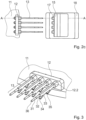
- Two joining stations 12 are shown on the circular disk 11, which have a plurality of receiving fingers 13, in the present example a total of four. Opposite these in a concentric alignment and essentially parallel to the radial extension A of the circular disk 11, pressure buttons 17 are arranged on a processing plate 15 of a processing station 16. This pressure plate 15 is movable so that it can move against the radial extension A towards the receiving fingers 13 and can accordingly exert a deformation on loaded cylinders.
- FIG. 2c This device is shown in plan view, in which the circular disk 11 has the said guide station 12, which has four radially extending receiving fingers 13.
- the longitudinal direction of the receiving fingers is concentric with the Press buttons 17 on a processing plate 15.
- the processing plate 15 is mounted on a rail so that it can be moved on a locking plate 18 in the direction of the receiving fingers to generate a contact pressure on them.
- the joining station 12 has four sleeves 12.2, from each of which a receiving finger 13 protrudes.
- the receiving finger 13 has a plurality of diameters 31, 32, 33.
- the finger 13 has a first diameter 33, starting from the sleeve.
- Two clamping mandrels 35, 34 are provided on this first diameter.
- This first diameter 33 is suitable for receiving an outer cylinder.
- the two clamping mandrels 33, 34 serve to hold this outer cylinder by means of a restoring force.
- the outer cylinder in the present example would be the last cylinder to be applied to the receiving finger.
- This first diameter is followed by a second diameter 32 which is smaller than the inner diameter of the first inner cylinder.
- this first inner cylinder would be the second cylinder to be applied in the present example, which relates to three-part tampon applicators.
- a third diameter which tapers over a shoulder and ends in a tip 36.
- This last diameter 31 is suitable for accommodating a second inner cylinder.
- a second outer cylinder would first be placed over this last diameter 31.
- the tapered area starting from the middle diameter 32, essentially releasably clamps the second inner cylinder to the receiving finger.
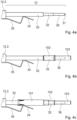
- FIG. 4a shows a receiving finger 13 in profile.
- the joining station would begin to the left of a sleeve 12.2.
- a first diameter 33 protrudes from the sleeve 12.2, which has two clamping mandrels 35, 34 shaped as brackets.
- the two clamping mandrels 35, 34 exert a restoring force on the receiving finger so that after receiving an outer cylinder, it is held in place.
- the first diameter 33 ends with a stop, which is followed by a second diameter 32.
- This second diameter 32 is followed by another stop and a section that tapers into the third diameter 36.
- the receiving finger ends in a substantially conical tip 31.
- the clamping mandrels 35, 34 which are shaped as brackets, exert a restoring force on the outer cylinder 101.
- a first bracket part 35 protrudes at an angle from the sleeve 12.2 and exerts a contact pressure on the outer cylinder 101.
- a second bracket part 34 is integral with the first bracket part 35, also protrudes at an angle and serves as a guide plate for receiving the outer cylinder 101.
- the Fig.5 shows a separating unit that can be used to separate outer cylinders for feeding. It is important that corresponding outer cylinders, which have a petal-shaped distal opening, are separated from each other, otherwise they can easily get caught and cannot be loaded onto the receiving fingers in an orderly manner.
- the cylinders 100 are conveyed on belts 73.
- Drive rollers 74.1, 74.2 drive the corresponding belts.
- a transfer from one belt system to the other takes place.
- Rubberized acceleration rollers 75.1, 75.2 are provided above this transfer point, which are also driven by a belt drive 77.1, 77.2.
- the outer cylinders 100 go from a drive with a first speed 70.1, 70.2 to an area with a drive with a second speed 75.1, 75.2.
- the acceleration separates any outer cylinders that are caught in one another.
- the belts are driven by drive shafts 71, 76 that run at different speeds.
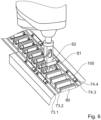
- the Fig.6 shows an alignment unit which also aligns the said outer cylinders 100 for loading the receiving fingers.
- the supply of the outer cylinders 100 is accomplished via two parallel belt drive systems with two belts 73.1, 73.2; 74.3, 74.4 each.
- a robot with a robot arm 82 and a gripper 81 grasps the outer cylinders 100 and transfers them to a conveyor system 80 in which the outer cylinders 100 are essentially parallel and all aligned the same.
- the supply ends in another robot system (not shown), which can, for example, remove a batch of outer cylinders from this conveyor unit 80 and load them onto the receiving fingers for loading.
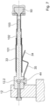
- the Figure 7 shows how a joining station 12 with a receiving finger is currently in operative connection with a processing station.
- the joining station 12 has an outer cylinder 101 on a sleeve 12.2 on a first diameter 33.
- a first inner cylinder 102 in which in turn is a second inner cylinder 103.
- the outer cylinder 101 is held by means of a spring-loaded clamping mandrel shaped as a bracket with a first bracket part 35 and a second bracket part 34.
- the processing station has a pressure button 50 which is formed concentrically to the longitudinal axis of the receiving finger and which slides into the proximal end of the second inner cylinder and widens it by means of a conical shape, so that an overall trumpet-shaped proximal end of the second inner cylinder 103 is produced.
- This transformation prevents the second inner cylinder 103 from falling out of the three-part tampon applicator, for example by pushing through the mouth of the outer cylinder 101.
- This step can complete a joining process according to the invention. However, this joining process can also take place over a number of individual sub-steps. For example, a first transformation can take place with a certain first contact pressure and a second transformation with a certain second contact pressure. A separate processing station with respective contact buttons can be provided for each transformation. This step-by-step transformation can be repeated as often as is necessary to obtain the desired trumpet-shaped expansion of the proximal end of the tampon applicator.
- the device according to the invention can be used to join tampon applicators from several hollow cylinders in a space-saving and efficient manner in a fast throughput. Particularly suitable is the device according to the invention for joining three-part tampon applicators with a telescopic plunger that is pulled out and locked into place.
Landscapes
- Health & Medical Sciences (AREA)
- Engineering & Computer Science (AREA)
- Life Sciences & Earth Sciences (AREA)
- Biomedical Technology (AREA)
- Heart & Thoracic Surgery (AREA)
- Vascular Medicine (AREA)
- Epidemiology (AREA)
- Animal Behavior & Ethology (AREA)
- General Health & Medical Sciences (AREA)
- Public Health (AREA)
- Veterinary Medicine (AREA)
- Manufacturing & Machinery (AREA)
- Mechanical Engineering (AREA)
- Absorbent Articles And Supports Therefor (AREA)
- Lining Or Joining Of Plastics Or The Like (AREA)
Claims (15)
- Dispositif pour assembler des applicateurs de tampon en plusieurs parties, en particulier des applicateurs de tampon en trois parties, dans lequel les applicateurs de tampon en plusieurs parties comprennent un cylindre externe (101) et un premier cylindre interne (102), le dispositif comprenant :a. au moins un poste d'assemblage (12) avec au moins un doigt de réception (13.1, 13.2) pour la réception d'un cylindre externe (101) et d'un premier cylindre interne (102) ;b. une première alimentation en cylindre interne pour munir l'au moins un doigt de réception d'au moins un premier cylindre interne (102) ;c. une alimentation en cylindre externe pour munir l'au moins un doigt de réception (13.1, 13.2) d'au moins un cylindre externe (101) ;d. un premier poste de traitement (16) pour assembler l'au moins un cylindre externe (101) avec l'au moins un premier cylindre interne (102), etcaractérisé en ce que
l'au moins un poste d'assemblage (12) est disposé radialement sur un disque circulaire (11), en particulier de sorte que l'au moins un doigt de réception (13.1, 13.2) soit aligné essentiellement radialement. - Dispositif selon la revendication 1, dans lequel les applicateurs de tampon en plusieurs parties comprennent un second cylindre interne, et le dispositif comprenant en outre :a. une seconde alimentation en cylindre interne pour munir l'au moins un doigt de réception d'au moins un second cylindre interne, et dans lequel
le premier poste de traitement est conçu pour assembler l'au moins un premier cylindre interne avec l'au moins un second cylindre interne. - Dispositif selon l'une des revendications 1 ou 2, dans lequel l'au moins un doigt de réception présente une pluralité de diamètres, en particulier dans lequel le doigt de réception présente un diamètre qui se rétrécit en alignement radial.
- Dispositif selon la revendication 3, dans lequel chaque diamètre est conçu pour accueillir un cylindre externe, un premier cylindre interne et un second cylindre interne.
- Dispositif selon l'une des revendications 1 à 4, dans lequel l'au moins un doigt de réception présente au moins un doigt pour le maintien d'un cylindre externe et/ou d'un premier cylindre interne.
- Dispositif selon l'une des revendications 1 à 5, dans lequel le premier poste de traitement et/ou un second poste de traitement est conçu pour former, en particulier thermiquement, un cylindre externe, un premier cylindre interne et/ou un second cylindre interne reçus sur un doigt de réception.
- Dispositif selon l'une des revendications 1 à 6, le dispositif comprenant une pluralité de postes d'assemblage, en particulier entre deux et vingt-quatre postes d'assemblage.
- Dispositif selon l'une des revendications 1 à 7, dans lequel chaque poste d'assemblage comprend une pluralité de doigts de réception pour recevoir chacun un cylindre externe et un premier cylindre interne, en particulier entre deux et seize doigts de réception.
- Dispositif selon l'une des revendications 1 à 8, dans lequel l'alimentation en cylindre externe comprend une unité de séparation.
- Dispositif selon l'une des revendications 1 à 9, dans lequel le disque circulaire est conçu pour pouvoir tourner, de sorte que le poste d'assemblage respectif peut être mis en liaison fonctionnelle avec, disposés radialement, une alimentation en cylindre interne, une alimentation en cylindre externe, un premier poste de traitement et un second poste de traitement.
- Procédé pour assembler des applicateurs de tampon en plusieurs parties, en particulier des applicateurs de tampon en trois parties, comprenant les étapes consistant à :a. aligner un poste d'assemblage avec une première alimentation en cylindre interne ;b. munir d'un premier cylindre interne un premier doigt de réception du poste d'assemblage ;c. aligner le poste d'assemblage avec une alimentation en cylindre externe ou une seconde alimentation en cylindre interne ;d. munir d'un cylindre externe ou d'un second cylindre interne le doigt de réception du poste d'assemblage,caractérisé en ce que
le poste d'assemblage (12) disposé radialement sur un disque circulaire (11) est aligné par une rotation circulaire du disque circulaire, en particulier de sorte que le doigt de réception est amené en liaison fonctionnelle coaxiale avec l'alimentation en cylindre interne et/ou l'alimentation en cylindre externe. - Procédé selon la revendication 10, comprenant en outre l'étape consistant à :a. aligner le poste d'assemblage avec un poste de formage ;b. former le premier cylindre interne et/ou le second cylindre interne par application de chaleur et de pression.
- Procédé selon l'une des revendications 11 ou 12, dans lequel, lors de l'étape consistant à munir le poste d'assemblage, le premier doigt de réception, en particulier une zone de pointe de plus petit diamètre du doigt de réception, est d'abord muni du cylindre interne de plus petit diamètre de l'applicateur de tampon en plusieurs parties.
- Procédé selon l'une des revendications 10 à 12, dans lequel le cylindre externe est serré, en particulier de manière amovible, sur le doigt de réception au moyen d'un mandrin de serrage qui exerce une force de rappel.
- Procédé selon l'une des revendications 10 à 12, dans lequel le cylindre externe est éjecté du doigt de réception au moyen d'un mandrin de serrage qui exerce une force de rappel.
Priority Applications (1)
| Application Number | Priority Date | Filing Date | Title |
|---|---|---|---|
| SI202130176T SI4132442T1 (sl) | 2020-04-06 | 2021-04-04 | Naprava in postopek za sestavljanje večdelnih aplikatorjev tamponov |
Applications Claiming Priority (2)
| Application Number | Priority Date | Filing Date | Title |
|---|---|---|---|
| CH00412/20A CH717298A1 (de) | 2020-04-06 | 2020-04-06 | Vorrichtung und Verfahren zum Fügen mehrteiliger Tampon-Applikatoren. |
| PCT/EP2021/058822 WO2021204732A1 (fr) | 2020-04-06 | 2021-04-04 | Dispositif et procédé pour assembler des applicateurs de tampon en plusieurs parties |
Publications (2)
| Publication Number | Publication Date |
|---|---|
| EP4132442A1 EP4132442A1 (fr) | 2023-02-15 |
| EP4132442B1 true EP4132442B1 (fr) | 2024-05-29 |
Family
ID=73020010
Family Applications (1)
| Application Number | Title | Priority Date | Filing Date |
|---|---|---|---|
| EP21716427.6A Active EP4132442B1 (fr) | 2020-04-06 | 2021-04-04 | Dispositif et procédé pour assembler des applicateurs de tampon en plusieurs parties |
Country Status (14)
| Country | Link |
|---|---|
| US (1) | US12465527B2 (fr) |
| EP (1) | EP4132442B1 (fr) |
| JP (1) | JP7597823B2 (fr) |
| KR (1) | KR20220163958A (fr) |
| CN (1) | CN115515544B (fr) |
| AU (1) | AU2021253122B2 (fr) |
| CH (1) | CH717298A1 (fr) |
| CO (1) | CO2022015064A2 (fr) |
| DK (1) | DK4132442T3 (fr) |
| IL (1) | IL297005A (fr) |
| MX (1) | MX2022009953A (fr) |
| SI (1) | SI4132442T1 (fr) |
| WO (1) | WO2021204732A1 (fr) |
| ZA (1) | ZA202210025B (fr) |
Family Cites Families (14)
| Publication number | Priority date | Publication date | Assignee | Title |
|---|---|---|---|---|
| US2624078A (en) * | 1947-08-08 | 1953-01-06 | Sanitary Tampon Corp | Machine for compressing and assembling tampons |
| US3568577A (en) * | 1967-12-12 | 1971-03-09 | Joseph A Voss | Applicators for catamenial devices |
| US4006515A (en) | 1974-12-10 | 1977-02-08 | The Procter & Gamble Company | Apparatus for forming tampons and assembling same in inserters |
| RU2044530C1 (ru) | 1993-09-28 | 1995-09-27 | Предприятие "Альберт" | Аппликатор для введения менструального тампона |
| US6343558B1 (en) | 1998-05-01 | 2002-02-05 | Daniel R. Shepard | Shuttle apparatus for high-speed lacing of an article |
| US6923789B2 (en) * | 2002-02-22 | 2005-08-02 | Playtex Products, Inc. | Multiple-component tampon applicator |
| CN103393502B (zh) | 2008-07-31 | 2015-07-29 | 尤妮佳股份有限公司 | 用于制造止血塞的装置及方法 |
| JP5314984B2 (ja) * | 2008-09-29 | 2013-10-16 | ユニ・チャーム株式会社 | タンポンの製造装置、及び、タンポンの製造方法 |
| DE102010055155A1 (de) * | 2010-12-15 | 2012-06-21 | Khs Corpoplast Gmbh | Verfahren zur Plasmabehandlung von Werkstücken sowie Werkstück mit Gasbarriereschicht |
| US8458882B2 (en) * | 2011-02-10 | 2013-06-11 | Kimberly-Clark Worldwide, Inc. | Method for assembling a tampon applicator |
| JP5715993B2 (ja) * | 2012-09-12 | 2015-05-13 | ユニ・チャーム株式会社 | タンポン用アプリケータ |
| GB2571875B (en) * | 2016-11-30 | 2021-10-13 | Kimberly Clark Co | Molding thermoplastic injection-molded and flushable materials |
| CH715069B1 (de) | 2018-06-05 | 2025-09-30 | Ruggli Ag | Fördereinrichtung und Verfahren zum Fördern von Tampon-Applikatoren. |
| CH715307A2 (de) | 2018-09-10 | 2020-03-13 | Ruggli Projects Ag | Vorrichtung und Verfahren zum Bestücken von Tampon-Applikatoren mit Tampons. |
-
2020
- 2020-04-06 CH CH00412/20A patent/CH717298A1/de unknown
-
2021
- 2021-04-04 KR KR1020227033886A patent/KR20220163958A/ko not_active Ceased
- 2021-04-04 AU AU2021253122A patent/AU2021253122B2/en active Active
- 2021-04-04 DK DK21716427.6T patent/DK4132442T3/da active
- 2021-04-04 SI SI202130176T patent/SI4132442T1/sl unknown
- 2021-04-04 US US17/916,859 patent/US12465527B2/en active Active
- 2021-04-04 CN CN202180021842.3A patent/CN115515544B/zh active Active
- 2021-04-04 IL IL297005A patent/IL297005A/en unknown
- 2021-04-04 JP JP2022551655A patent/JP7597823B2/ja active Active
- 2021-04-04 WO PCT/EP2021/058822 patent/WO2021204732A1/fr not_active Ceased
- 2021-04-04 EP EP21716427.6A patent/EP4132442B1/fr active Active
- 2021-04-04 MX MX2022009953A patent/MX2022009953A/es unknown
-
2022
- 2022-09-08 ZA ZA2022/10025A patent/ZA202210025B/en unknown
- 2022-10-21 CO CONC2022/0015064A patent/CO2022015064A2/es unknown
Also Published As
| Publication number | Publication date |
|---|---|
| ZA202210025B (en) | 2024-01-31 |
| WO2021204732A1 (fr) | 2021-10-14 |
| KR20220163958A (ko) | 2022-12-12 |
| US20230157902A1 (en) | 2023-05-25 |
| MX2022009953A (es) | 2022-11-30 |
| EP4132442A1 (fr) | 2023-02-15 |
| SI4132442T1 (sl) | 2024-09-30 |
| JP7597823B2 (ja) | 2024-12-10 |
| CH717298A1 (de) | 2021-10-15 |
| JP2023519129A (ja) | 2023-05-10 |
| AU2021253122A1 (en) | 2022-09-29 |
| US12465527B2 (en) | 2025-11-11 |
| CO2022015064A2 (es) | 2022-12-30 |
| DK4132442T3 (da) | 2024-07-29 |
| CN115515544A (zh) | 2022-12-23 |
| IL297005A (en) | 2022-12-01 |
| BR112022016329A2 (pt) | 2022-10-04 |
| AU2021253122B2 (en) | 2025-10-23 |
| CN115515544B (zh) | 2025-04-18 |
Similar Documents
| Publication | Publication Date | Title |
|---|---|---|
| EP0472863B1 (fr) | Dispositif pour préparer des faisceaux de poils pour la fabrication des brosses | |
| DE3049581C2 (de) | Vorrichtung zum Herstellen von mit einem Rückholband versehenen Tampons für die Frauenhygiene | |
| DE102018121745A1 (de) | Verfahren und Vorrichtung zum Herstellen einer Anordnung von Spulenelementen für eine Steckspule einer elektrischen Maschine | |
| EP0062144A2 (fr) | Procédé et appareil pour calibrer des corps creux en matière thermoplastique orientés biaxialement | |
| EP3037016B1 (fr) | Machine de fabrication de brosse et procede d'insertion de faisceaux de soies dans des ouvertures d'un support de faisceau | |
| EP1022821B1 (fr) | Méthode et dispositif pour appliquer des manchons | |
| DE2262582C3 (de) | Vorrichtung zur Herstellung mehrschichtiger Hohlkörper aus Kunststoff durch Spritzblasen | |
| DE1945427B2 (de) | Vorrichtung zum herstellen von tampons | |
| EP1397967B1 (fr) | Fabrication d'éléments de filtre ne pouvant pas être découpés | |
| EP3849484B1 (fr) | Dispositif et procédé d'équipement en tampons d'applicateurs de tampon | |
| EP0929395B1 (fr) | Installation pour la fabrication de tubes a deux ou plusieurs compartiments | |
| EP0680916A1 (fr) | Procédé de traitement de produits imprimés | |
| DE4141645C2 (de) | Verfahren und Vorrichtung zum Herstellen eines Kunststoffbehälters mit einem Hüllfolien-Saughaltedorn | |
| CH717298A1 (de) | Vorrichtung und Verfahren zum Fügen mehrteiliger Tampon-Applikatoren. | |
| EP0280203B1 (fr) | Procédé et appareil pour la fabrication de corps creux en matière thermoplastique orientée | |
| DE4430172C2 (de) | Einrichtung zur Herstellung von Brezeln | |
| EP4028183B1 (fr) | Dispositif et procédé de laminage par étirage | |
| DE102015219446B3 (de) | Rohbaufertigungsanlage mit verstellbaren Vorrichtungstischen an mindestens einem Rüstplatz sowie Verfahren zur Herstellung von zwei zueinander unterschiedlichen Fertigungsbauteilen in einer Rohbaufertigungsanlage | |
| DE60312761T2 (de) | Verfahren und Vorrichtung zur Beschickung von chirurgischen Nadeln in chirurgische Nahtpackungen | |
| EP1332814A2 (fr) | Dispositif d'avancement d'une barre pour tours d'usinage | |
| DE3339017A1 (de) | Vorrichtung und verfahren zum kuehlen der dorne einer spritzblasformmaschine | |
| EP3722472B1 (fr) | Métier à tricoter rectiligne pourvu de dispositif d'introduction des éléments d'insertion dans un tricot | |
| EP4469259B1 (fr) | Procédé et dispositif de dilatation d'ébauches de tubes | |
| DE69024059T2 (de) | Vorrichtung und verfahren zum vorlochen von blöcken. | |
| DE1167003B (de) | Vorrichtung zur vollautomatischen Tubenherstellung aus thermoplastischen Kunststoffen |
Legal Events
| Date | Code | Title | Description |
|---|---|---|---|
| STAA | Information on the status of an ep patent application or granted ep patent |
Free format text: STATUS: UNKNOWN |
|
| STAA | Information on the status of an ep patent application or granted ep patent |
Free format text: STATUS: THE INTERNATIONAL PUBLICATION HAS BEEN MADE |
|
| PUAI | Public reference made under article 153(3) epc to a published international application that has entered the european phase |
Free format text: ORIGINAL CODE: 0009012 |
|
| STAA | Information on the status of an ep patent application or granted ep patent |
Free format text: STATUS: REQUEST FOR EXAMINATION WAS MADE |
|
| 17P | Request for examination filed |
Effective date: 20221104 |
|
| AK | Designated contracting states |
Kind code of ref document: A1 Designated state(s): AL AT BE BG CH CY CZ DE DK EE ES FI FR GB GR HR HU IE IS IT LI LT LU LV MC MK MT NL NO PL PT RO RS SE SI SK SM TR |
|
| DAV | Request for validation of the european patent (deleted) | ||
| DAX | Request for extension of the european patent (deleted) | ||
| P01 | Opt-out of the competence of the unified patent court (upc) registered |
Effective date: 20230530 |
|
| GRAP | Despatch of communication of intention to grant a patent |
Free format text: ORIGINAL CODE: EPIDOSNIGR1 |
|
| STAA | Information on the status of an ep patent application or granted ep patent |
Free format text: STATUS: GRANT OF PATENT IS INTENDED |
|
| INTG | Intention to grant announced |
Effective date: 20231027 |
|
| GRAS | Grant fee paid |
Free format text: ORIGINAL CODE: EPIDOSNIGR3 |
|
| RAP1 | Party data changed (applicant data changed or rights of an application transferred) |
Owner name: RUGGLI AG |
|
| GRAA | (expected) grant |
Free format text: ORIGINAL CODE: 0009210 |
|
| STAA | Information on the status of an ep patent application or granted ep patent |
Free format text: STATUS: THE PATENT HAS BEEN GRANTED |
|
| AK | Designated contracting states |
Kind code of ref document: B1 Designated state(s): AL AT BE BG CH CY CZ DE DK EE ES FI FR GB GR HR HU IE IS IT LI LT LU LV MC MK MT NL NO PL PT RO RS SE SI SK SM TR |
|
| REG | Reference to a national code |
Ref country code: CH Ref legal event code: EP |
|
| REG | Reference to a national code |
Ref country code: IE Ref legal event code: FG4D Free format text: LANGUAGE OF EP DOCUMENT: GERMAN |
|
| REG | Reference to a national code |
Ref country code: DE Ref legal event code: R096 Ref document number: 502021003864 Country of ref document: DE |
|
| REG | Reference to a national code |
Ref country code: DK Ref legal event code: T3 Effective date: 20240722 |
|
| REG | Reference to a national code |
Ref country code: SE Ref legal event code: TRGR |
|
| REG | Reference to a national code |
Ref country code: NL Ref legal event code: FP |
|
| REG | Reference to a national code |
Ref country code: CH Ref legal event code: PK Free format text: BERICHTIGUNGEN |
|
| REG | Reference to a national code |
Ref country code: LT Ref legal event code: MG9D |
|
| PG25 | Lapsed in a contracting state [announced via postgrant information from national office to epo] |
Ref country code: IS Free format text: LAPSE BECAUSE OF FAILURE TO SUBMIT A TRANSLATION OF THE DESCRIPTION OR TO PAY THE FEE WITHIN THE PRESCRIBED TIME-LIMIT Effective date: 20240929 |
|
| PG25 | Lapsed in a contracting state [announced via postgrant information from national office to epo] |
Ref country code: BG Free format text: LAPSE BECAUSE OF FAILURE TO SUBMIT A TRANSLATION OF THE DESCRIPTION OR TO PAY THE FEE WITHIN THE PRESCRIBED TIME-LIMIT Effective date: 20240529 |
|
| PG25 | Lapsed in a contracting state [announced via postgrant information from national office to epo] |
Ref country code: HR Free format text: LAPSE BECAUSE OF FAILURE TO SUBMIT A TRANSLATION OF THE DESCRIPTION OR TO PAY THE FEE WITHIN THE PRESCRIBED TIME-LIMIT Effective date: 20240529 Ref country code: FI Free format text: LAPSE BECAUSE OF FAILURE TO SUBMIT A TRANSLATION OF THE DESCRIPTION OR TO PAY THE FEE WITHIN THE PRESCRIBED TIME-LIMIT Effective date: 20240529 |
|
| PG25 | Lapsed in a contracting state [announced via postgrant information from national office to epo] |
Ref country code: GR Free format text: LAPSE BECAUSE OF FAILURE TO SUBMIT A TRANSLATION OF THE DESCRIPTION OR TO PAY THE FEE WITHIN THE PRESCRIBED TIME-LIMIT Effective date: 20240830 |
|
| PG25 | Lapsed in a contracting state [announced via postgrant information from national office to epo] |
Ref country code: LV Free format text: LAPSE BECAUSE OF FAILURE TO SUBMIT A TRANSLATION OF THE DESCRIPTION OR TO PAY THE FEE WITHIN THE PRESCRIBED TIME-LIMIT Effective date: 20240529 |
|
| PG25 | Lapsed in a contracting state [announced via postgrant information from national office to epo] |
Ref country code: NO Free format text: LAPSE BECAUSE OF FAILURE TO SUBMIT A TRANSLATION OF THE DESCRIPTION OR TO PAY THE FEE WITHIN THE PRESCRIBED TIME-LIMIT Effective date: 20240829 Ref country code: LV Free format text: LAPSE BECAUSE OF FAILURE TO SUBMIT A TRANSLATION OF THE DESCRIPTION OR TO PAY THE FEE WITHIN THE PRESCRIBED TIME-LIMIT Effective date: 20240529 Ref country code: IS Free format text: LAPSE BECAUSE OF FAILURE TO SUBMIT A TRANSLATION OF THE DESCRIPTION OR TO PAY THE FEE WITHIN THE PRESCRIBED TIME-LIMIT Effective date: 20240929 Ref country code: HR Free format text: LAPSE BECAUSE OF FAILURE TO SUBMIT A TRANSLATION OF THE DESCRIPTION OR TO PAY THE FEE WITHIN THE PRESCRIBED TIME-LIMIT Effective date: 20240529 Ref country code: GR Free format text: LAPSE BECAUSE OF FAILURE TO SUBMIT A TRANSLATION OF THE DESCRIPTION OR TO PAY THE FEE WITHIN THE PRESCRIBED TIME-LIMIT Effective date: 20240830 Ref country code: FI Free format text: LAPSE BECAUSE OF FAILURE TO SUBMIT A TRANSLATION OF THE DESCRIPTION OR TO PAY THE FEE WITHIN THE PRESCRIBED TIME-LIMIT Effective date: 20240529 Ref country code: BG Free format text: LAPSE BECAUSE OF FAILURE TO SUBMIT A TRANSLATION OF THE DESCRIPTION OR TO PAY THE FEE WITHIN THE PRESCRIBED TIME-LIMIT Effective date: 20240529 Ref country code: RS Free format text: LAPSE BECAUSE OF FAILURE TO SUBMIT A TRANSLATION OF THE DESCRIPTION OR TO PAY THE FEE WITHIN THE PRESCRIBED TIME-LIMIT Effective date: 20240829 |
|
| REG | Reference to a national code |
Ref country code: ES Ref legal event code: FG2A Ref document number: 2986636 Country of ref document: ES Kind code of ref document: T3 Effective date: 20241112 |
|
| PG25 | Lapsed in a contracting state [announced via postgrant information from national office to epo] |
Ref country code: EE Free format text: LAPSE BECAUSE OF FAILURE TO SUBMIT A TRANSLATION OF THE DESCRIPTION OR TO PAY THE FEE WITHIN THE PRESCRIBED TIME-LIMIT Effective date: 20240529 |
|
| PG25 | Lapsed in a contracting state [announced via postgrant information from national office to epo] |
Ref country code: SK Free format text: LAPSE BECAUSE OF FAILURE TO SUBMIT A TRANSLATION OF THE DESCRIPTION OR TO PAY THE FEE WITHIN THE PRESCRIBED TIME-LIMIT Effective date: 20240529 Ref country code: RO Free format text: LAPSE BECAUSE OF FAILURE TO SUBMIT A TRANSLATION OF THE DESCRIPTION OR TO PAY THE FEE WITHIN THE PRESCRIBED TIME-LIMIT Effective date: 20240529 |
|
| PG25 | Lapsed in a contracting state [announced via postgrant information from national office to epo] |
Ref country code: SM Free format text: LAPSE BECAUSE OF FAILURE TO SUBMIT A TRANSLATION OF THE DESCRIPTION OR TO PAY THE FEE WITHIN THE PRESCRIBED TIME-LIMIT Effective date: 20240529 |
|
| PG25 | Lapsed in a contracting state [announced via postgrant information from national office to epo] |
Ref country code: SM Free format text: LAPSE BECAUSE OF FAILURE TO SUBMIT A TRANSLATION OF THE DESCRIPTION OR TO PAY THE FEE WITHIN THE PRESCRIBED TIME-LIMIT Effective date: 20240529 Ref country code: SK Free format text: LAPSE BECAUSE OF FAILURE TO SUBMIT A TRANSLATION OF THE DESCRIPTION OR TO PAY THE FEE WITHIN THE PRESCRIBED TIME-LIMIT Effective date: 20240529 Ref country code: RO Free format text: LAPSE BECAUSE OF FAILURE TO SUBMIT A TRANSLATION OF THE DESCRIPTION OR TO PAY THE FEE WITHIN THE PRESCRIBED TIME-LIMIT Effective date: 20240529 Ref country code: EE Free format text: LAPSE BECAUSE OF FAILURE TO SUBMIT A TRANSLATION OF THE DESCRIPTION OR TO PAY THE FEE WITHIN THE PRESCRIBED TIME-LIMIT Effective date: 20240529 |
|
| REG | Reference to a national code |
Ref country code: DE Ref legal event code: R097 Ref document number: 502021003864 Country of ref document: DE |
|
| PLBE | No opposition filed within time limit |
Free format text: ORIGINAL CODE: 0009261 |
|
| STAA | Information on the status of an ep patent application or granted ep patent |
Free format text: STATUS: NO OPPOSITION FILED WITHIN TIME LIMIT |
|
| PGFP | Annual fee paid to national office [announced via postgrant information from national office to epo] |
Ref country code: SI Payment date: 20250327 Year of fee payment: 5 |
|
| PGFP | Annual fee paid to national office [announced via postgrant information from national office to epo] |
Ref country code: PL Payment date: 20250327 Year of fee payment: 5 |
|
| 26N | No opposition filed |
Effective date: 20250303 |
|
| PGFP | Annual fee paid to national office [announced via postgrant information from national office to epo] |
Ref country code: NL Payment date: 20250418 Year of fee payment: 5 |
|
| PGFP | Annual fee paid to national office [announced via postgrant information from national office to epo] |
Ref country code: LU Payment date: 20250418 Year of fee payment: 5 |
|
| PGFP | Annual fee paid to national office [announced via postgrant information from national office to epo] |
Ref country code: DE Payment date: 20250422 Year of fee payment: 5 |
|
| PGFP | Annual fee paid to national office [announced via postgrant information from national office to epo] |
Ref country code: DK Payment date: 20250429 Year of fee payment: 5 Ref country code: GB Payment date: 20250423 Year of fee payment: 5 Ref country code: ES Payment date: 20250530 Year of fee payment: 5 |
|
| PGFP | Annual fee paid to national office [announced via postgrant information from national office to epo] |
Ref country code: IT Payment date: 20250424 Year of fee payment: 5 Ref country code: BE Payment date: 20250418 Year of fee payment: 5 |
|
| PGFP | Annual fee paid to national office [announced via postgrant information from national office to epo] |
Ref country code: FR Payment date: 20250425 Year of fee payment: 5 |
|
| PGFP | Annual fee paid to national office [announced via postgrant information from national office to epo] |
Ref country code: CH Payment date: 20250501 Year of fee payment: 5 |
|
| PGFP | Annual fee paid to national office [announced via postgrant information from national office to epo] |
Ref country code: AT Payment date: 20250721 Year of fee payment: 5 |
|
| PGFP | Annual fee paid to national office [announced via postgrant information from national office to epo] |
Ref country code: CZ Payment date: 20250401 Year of fee payment: 5 |
|
| PGFP | Annual fee paid to national office [announced via postgrant information from national office to epo] |
Ref country code: SE Payment date: 20250429 Year of fee payment: 5 |
|
| PG25 | Lapsed in a contracting state [announced via postgrant information from national office to epo] |
Ref country code: MC Free format text: LAPSE BECAUSE OF FAILURE TO SUBMIT A TRANSLATION OF THE DESCRIPTION OR TO PAY THE FEE WITHIN THE PRESCRIBED TIME-LIMIT Effective date: 20240529 |
|
| PG25 | Lapsed in a contracting state [announced via postgrant information from national office to epo] |
Ref country code: IE Free format text: LAPSE BECAUSE OF NON-PAYMENT OF DUE FEES Effective date: 20250404 |