EP4132753B1 - Système et procédé d'assemblage automatisé d'éléments - Google Patents
Système et procédé d'assemblage automatisé d'éléments Download PDFInfo
- Publication number
- EP4132753B1 EP4132753B1 EP21784404.2A EP21784404A EP4132753B1 EP 4132753 B1 EP4132753 B1 EP 4132753B1 EP 21784404 A EP21784404 A EP 21784404A EP 4132753 B1 EP4132753 B1 EP 4132753B1
- Authority
- EP
- European Patent Office
- Prior art keywords
- component
- shaft
- tool
- manipulator
- supported
- Prior art date
- Legal status (The legal status is an assumption and is not a legal conclusion. Google has not performed a legal analysis and makes no representation as to the accuracy of the status listed.)
- Active
Links
Images


Classifications
-
- B—PERFORMING OPERATIONS; TRANSPORTING
- B62—LAND VEHICLES FOR TRAVELLING OTHERWISE THAN ON RAILS
- B62D—MOTOR VEHICLES; TRAILERS
- B62D65/00—Designing, manufacturing, e.g. assembling, facilitating disassembly, or structurally modifying motor vehicles or trailers, not otherwise provided for
- B62D65/02—Joining sub-units or components to, or positioning sub-units or components with respect to, body shell or other sub-units or components
- B62D65/024—Positioning of sub-units or components with respect to body shell or other sub-units or components
-
- B—PERFORMING OPERATIONS; TRANSPORTING
- B25—HAND TOOLS; PORTABLE POWER-DRIVEN TOOLS; MANIPULATORS
- B25J—MANIPULATORS; CHAMBERS PROVIDED WITH MANIPULATION DEVICES
- B25J15/00—Gripping heads and other end effectors
- B25J15/0052—Gripping heads and other end effectors multiple gripper units or multiple end effectors
- B25J15/0061—Gripping heads and other end effectors multiple gripper units or multiple end effectors mounted on a modular gripping structure
-
- B—PERFORMING OPERATIONS; TRANSPORTING
- B25—HAND TOOLS; PORTABLE POWER-DRIVEN TOOLS; MANIPULATORS
- B25J—MANIPULATORS; CHAMBERS PROVIDED WITH MANIPULATION DEVICES
- B25J9/00—Program-controlled manipulators
- B25J9/003—Program-controlled manipulators having parallel kinematics
- B25J9/0033—Program-controlled manipulators having parallel kinematics with kinematics chains having a prismatic joint at the base
-
- B—PERFORMING OPERATIONS; TRANSPORTING
- B62—LAND VEHICLES FOR TRAVELLING OTHERWISE THAN ON RAILS
- B62D—MOTOR VEHICLES; TRAILERS
- B62D65/00—Designing, manufacturing, e.g. assembling, facilitating disassembly, or structurally modifying motor vehicles or trailers, not otherwise provided for
- B62D65/02—Joining sub-units or components to, or positioning sub-units or components with respect to, body shell or other sub-units or components
- B62D65/06—Joining sub-units or components to, or positioning sub-units or components with respect to, body shell or other sub-units or components the sub-units or components being doors, windows, openable roofs, lids, bonnets, or weather strips or seals therefor
-
- B—PERFORMING OPERATIONS; TRANSPORTING
- B65—CONVEYING; PACKING; STORING; HANDLING THIN OR FILAMENTARY MATERIAL
- B65G—TRANSPORT OR STORAGE DEVICES, e.g. CONVEYORS FOR LOADING OR TIPPING, SHOP CONVEYOR SYSTEMS OR PNEUMATIC TUBE CONVEYORS
- B65G47/00—Article or material-handling devices associated with conveyors; Methods employing such devices
- B65G47/74—Feeding, transfer, or discharging devices of particular kinds or types
- B65G47/90—Devices for picking-up and depositing articles or materials
- B65G47/91—Devices for picking-up and depositing articles or materials incorporating pneumatic, e.g. suction, grippers
- B65G47/914—Devices for picking-up and depositing articles or materials incorporating pneumatic, e.g. suction, grippers provided with drive systems incorporating rotary and rectilinear movements
-
- B—PERFORMING OPERATIONS; TRANSPORTING
- B65—CONVEYING; PACKING; STORING; HANDLING THIN OR FILAMENTARY MATERIAL
- B65G—TRANSPORT OR STORAGE DEVICES, e.g. CONVEYORS FOR LOADING OR TIPPING, SHOP CONVEYOR SYSTEMS OR PNEUMATIC TUBE CONVEYORS
- B65G47/00—Article or material-handling devices associated with conveyors; Methods employing such devices
- B65G47/74—Feeding, transfer, or discharging devices of particular kinds or types
- B65G47/90—Devices for picking-up and depositing articles or materials
- B65G47/91—Devices for picking-up and depositing articles or materials incorporating pneumatic, e.g. suction, grippers
- B65G47/918—Devices for picking-up and depositing articles or materials incorporating pneumatic, e.g. suction, grippers with at least two picking-up heads
-
- B—PERFORMING OPERATIONS; TRANSPORTING
- B25—HAND TOOLS; PORTABLE POWER-DRIVEN TOOLS; MANIPULATORS
- B25J—MANIPULATORS; CHAMBERS PROVIDED WITH MANIPULATION DEVICES
- B25J15/00—Gripping heads and other end effectors
- B25J15/06—Gripping heads and other end effectors with vacuum or magnetic holding means
- B25J15/0616—Gripping heads and other end effectors with vacuum or magnetic holding means with vacuum
-
- B—PERFORMING OPERATIONS; TRANSPORTING
- B65—CONVEYING; PACKING; STORING; HANDLING THIN OR FILAMENTARY MATERIAL
- B65G—TRANSPORT OR STORAGE DEVICES, e.g. CONVEYORS FOR LOADING OR TIPPING, SHOP CONVEYOR SYSTEMS OR PNEUMATIC TUBE CONVEYORS
- B65G2811/00—Indexing codes relating to common features for more than one conveyor kind or type
- B65G2811/06—Devices controlling the relative position of articles
- B65G2811/0647—Changing the direction of movement of articles or bulk material
- B65G2811/0663—Pick-up means
Definitions
- the present invention relates generally to automated manufacturing systems and, more particularly, to a system and method for automated assembly of components.
- Automation plays an ever-increasing role in the manufacturing and assembly of products.
- manufacturing systems become more and more automated, there is a corresponding increased use of robotic manipulators to fabricate, process, and assemble components and sub-assemblies into end products.
- One example of such automated manufacturing systems can be found in the automotive industry, where automated manufacturing lines assemble completed vehicles from component parts.
- Many automated manufacturing systems utilize assembly lines having multi-axis robotic manipulators cooperating in a coordinated manner to process and assemble components into a desired end product.
- these multi-axis robotic manipulators comprise a plurality of serially arranged links that are moved by motors to perform the processing and assembly functions.
- a hand for parallel link robot includes: a holder configured to extract a workpiece from an extraction portion and hold the workpiece; and a swing-up mechanism portion configured to swing the workpiece held by the holder up centering around a turning axis to change a posture of the workpiece, and a parallel link robot includes: a link mechanism portion; and the hand mounted to the link mechanism portion.
- a workpiece conveyor that conveys a workpiece includes chucks that hold a workpiece, and a movable body that supports the chucks and is movable in an X direction along first and second guides, which are disposed in parallel or substantially parallel spaced apart from each other, and the movable body includes a first structure guided by the first guide, a second structure guided by the second guide, and a joint that is provided between the first structure and the second structure, and allows one of the first structure and the second structure to swing with respect to the other about an axis of a swing shaft set parallel or substantially parallel to the X direction.
- a device for harvesting mushrooms from a mushroom bed involves a robotic aim configured to interchangeably deploy one of a plurality of different suction grippers, each of the suction grippers having a suction cup having a size and shape profile appropriate for gripping a cap of a mushroom, the cap having a size and shape profile within a predetermined range.
- the present invention provides a system and associated method for the automated assembly of components to a workpiece on an assembly line.
- an exemplary system for automatically handling components to be assembled onto a product on an assembly line includes a carriage supported on a frame that positions the system adjacent the assembly line.
- the carriage is movable to and between a first, retracted position spaced a distance away from the assembly line, and a second, work position displaced from the retracted position in a direction toward the assembly line.
- the carriage supports a multi-axis articulating manipulator that, in turn, supports a component mounting tool configured to receive and support at least one component for assembly to the product.
- the manipulator may be arranged in a first orientation when the carriage is in the first position, and may be pivoted to a second orientation when the carriage is in the second position such that a component on the component mounting tool is supported in a pose for processing when the carriage is in the first position, and the component is supported in a pose for joining to the product when the carriage is in the second position.
- a method of handling components to be assembled to a product on an assembly line includes receiving the component on a component mounting tool at a first, retracted position spaced from the assembly line, and moving the component mounting tool in a direction toward the assembly line to a second, work position.
- the component mounting tool In the first position, the component mounting tool is in a first pose adapted to facilitate receiving or processing the component.
- In the second position, the component mounting tool In the second position, the component mounting tool is in a second pose adapted to facilitate joining the component to the product.
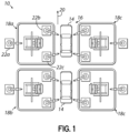
- FIG. 1 depicts an exemplary manufacturing plant 10 including an exemplary system 12 for automatically handling components to be assembled onto a workpiece 14 that is moved along a manufacturing assembly line 16 in accordance with the principles of the present disclosure.
- the manufacturing plant 10 comprises a plurality of individual manufacturing cells 18a, 18b, 18c, 18d positioned adjacent the manufacturing assembly line 16 and disposed on either side of the assembly line 16.
- the assembly line 16 may include conveying structure (not shown) for automated movement of workpieces 14 along the assembly line 16 (such as in the direction of arrow 20), whereby the workpieces 14 may be positioned adjacent the plurality of manufacturing cells 18a - 18d and automated systems, such as robotic manipulators, assemble components onto the workpieces 14 or process the workpieces 14 as part of the manufacturing process.
- the workpieces 14 are depicted as automotive vehicles, and the cells 18a - 18d of the manufacturing plant 10 are configured to assemble components onto the vehicle body or to perform various processing steps which may be desired. While the exemplary embodiment is shown and described herein as a manufacturing plant 10 with cells 18a - 18d adapted to assemble and process vehicles, it will be appreciated that the manufacturing plant 10 and cells 18a - 18d may alternatively be configured to produce various other products.
- an exemplary manufacturing cell 18a may include an exemplary component handling system 12 in accordance with the principles of the present disclosure.
- the component handling system 12 may be arranged in the cell 18a adjacent a plurality of robotic manipulators.
- a first robotic manipulator 22a may be configured to pick one or more components from a supply (not shown) and position the components on or within the component handling system 12.
- the first robotic manipulator 22a may be situated within the manufacturing cell 18a or, alternatively, may be placed adjacent the manufacturing cell 18a and may be configured to extend within the manufacturing cell 18a in cooperation with the component handling system 12.
- Additional robotic manipulators 22b, 22c may be positioned within the cell 18a and may be configured to cooperate with the component handling system 12 to facilitate the assembly of and/or processing of components that are positioned by the component handling system 12 for assembly onto the workpiece 14. While the exemplary manufacturing cell 18a has been shown and described herein as including several robotic manipulators 22a, 22b, 22c which cooperate with the component handling system 12, it will be appreciated that various other configurations of manufacturing cells may alternatively be used.
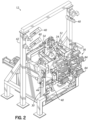
- the component handling system 12 may be supported on a frame 30 for location within a manufacturing cell 18a and adjacent the manufacturing line 16.
- the exemplary component handling system 12 includes a multi-axis articulating manipulator 32 supported on the frame 30 by a carriage 34.
- the carriage 34 is supported on the frame 30 for movement to and between a first, retracted position that is spaced a distance away from the assembly line, as depicted in FIG.
- the carriage 34 is selectively moved between the first and second positions by an actuator 26 having an extendable rod 28. It will be appreciated, however, that various other mechanisms suitable for moving the carriage 34 between the first and second positions may be used.
- the exemplary component handling system 12 further includes a component mounting tool 36 coupled with the multi-axis manipulator 32 and configured to receive and support at least one component 38 for assembly to the workpiece 14.
- the component 38 is illustrated as a door that is to be mounted to the vehicle body as the vehicle body moves along the assembly line 16 and is positioned adjacent the manufacturing cell 18a. While the component 38 is shown and described herein as a vehicle door, it will be appreciated that, in other embodiments, various other components may be received on the component mounting tool 36 for processing and/or assembly onto a workpiece.
- automotive components such as body panels, handles, or hinges, or even non-automotive components, may be received and supported on a component mounting tool in accordance with the principles of the present disclosure.
- the mounting tool 36 when the carriage 34 is in the first, retracted position, the mounting tool 36 is oriented and positioned to receive a component 38, and supports the component 38 in a pose that facilitates further processing of the component 38, such as by a robotic manipulator 22a positioned adjacent the component handling system 12.
- the component 38 in the form of a vehicle door, may be supported with an interior side of the door facing up to thereby facilitate the positioning and attachment of sub-components onto the door.
- the first position of the carriage 34 facilitates the loading and processing of components and sub-components while the workpiece 14 is moving between the manufacturing cells 18a - 18d of the manufacturing assembly line 16, thereby providing increased efficiencies of throughput.
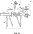
- the mounting tool 36 is moved in translation with the carriage 34, and is also moved in a curvilinear manner such that the mounting tool 36 supports the component 38 in a second pose that facilitates joining the component 38 to the workpiece 14.
- the component 38 may be supported in a generally vertical orientation of the door corresponding to how the door will be attached to the vehicle body (workpiece 14).
- the component handling system 12 may additionally be provided with various sensors for monitoring and facilitating the operation of the component handling system 12.
- the system 12 may further include one or more optical sensors, or cameras 40 positioned at various suitable locations on or near the manipulator 32, the carriage 34, and/or the component mounting tool 36.
- the optical sensors 40 may be supported on a separate support frame 42, for example, or may be coupled with the frame 30 or other structure as may be desired.
- Other sensors may include, as a non-limiting examples, one or more non-contact proximity sensors 44 positioned on or near the component handling system 12 and configured to sense the presence of a workpiece 14 adjacent the component handling system 12. Other sensors may be used to confirm the presence and/or pose of a component supported on the component mounting tool 36. Signals or data obtained from the sensors 40, 44 may be provided to a controller or other suitable computer and used to control and/or monitor operation of the component handling system 12.
- the exemplary multi-axis articulating manipulator 32 will be described in more detail.
- the manipulator 32 includes a base assembly 50 coupling the manipulator 32 to the carriage 34 for movement with the carriage 34 between the first and second positions on the frame 30.
- a plurality of linkages 52 are coupled with a base plate 54 of the base assembly 50 and are configured to support a tool mounting plate 56 on their opposite ends for coupling with the component mounting tool 36.
- the manipulator 32 includes three fixed-length linkages 52 coupled at their first ends 58 to the base plate 54, and the second ends 60 of the linkages 52 are coupled with the tool mounting plate 56.
- the first ends 58 of the linkages 58 are coupled to the base plate 54 by respective pivot joints 62 and at least one actuator configured to move the second ends 60 of the linkages 52 in a controllable manner. Through coordinated movement of the second ends 60 of the linkages 52, the pose (position and orientation) of the tool mounting plate 56 may be precisely controlled.
- the first end 58 of each linkage 52 is coupled to the base plate 54 by a pair of linear actuators 66a, 66b that are aligned to control movement of the first ends 58 of the linkages 52 in respective first and second directions 68, 70 arranged orthogonal to one another.
- the second ends 60 of the linkages 52 are coupled to the tool mounting plate 56 by respective swivel joints 72 such that the pose of the tool mounting plate 56 may be controlled by selective positioning of the linear actuators 66a, 66b coupled with the respective linkages 52.
- the multi-axis manipulator 32 facilitates precise positioning of a component 38 supported by the component mounting tool 36 that is coupled with the tool mounting plate 56 when the carriage 34 is in the second position.
- the base plate 54 of the multi-axis manipulator 32 When the carriage 34 is in the first position as shown in FIG. 3A , the base plate 54 of the multi-axis manipulator 32 is oriented such that the component mounting tool 36 coupled with tool mounting plate 56 is in the pose described above for receiving and supporting a component 38. As the carriage is moved from the first position to the second position, the base plate 54 pivots to an orientation such that the component mounting tool 36 coupled with tool mounting plate 56 is moved to the pose described above for joining the component 38 to the workpiece 14, as depicted in FIGS. 2 and 3B .
- multi-axis manipulator 32 has been shown and described herein as including three, fixed-length linkages 52, and linear actuators 66a, 66b coupling the linkages 52 to the manipulator base plate 54, it will be appreciated that various other arrangements of linkages and actuators, including variable length linkages, may alternatively be used to facilitate positioning the tool mounting plate 56 at a desired pose for mounting a component 38 to a workpiece 14.
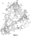
- the component mounting tool 36 includes a tool frame 80 configured to be coupled with the tool mounting plate 56 of the multi-axis manipulator 32.
- One or more shaft assemblies 82a, 82b are supported on the tool frame 80 and, in turn, support gripping members 84 configured to engage and support components 38 to be installed to the workpiece 14.
- the mounting tool 36 includes first and second shaft assemblies 82a, 82b supported on the tool frame 80.
- Each shaft assembly 82a, 82b includes a shaft 86a, 86b supported for rotation relative to the tool frame 80 by respective trunnion mounts 88.
- Each shaft 86a, 86b may further include a plurality of gripping members 84 positioned at spaced-apart circumferential positions around the shaft 86.
- each gripping member 84 may be configured to engage components having different geometries, whereby certain ones of the gripping members 84 may be selectively positioned for engagement with components 38 to be assembled to the workpiece 14 by rotating the shafts 86 about their respective longitudinal axes 90a, 90b relative to the frame 80.
- the component mounting tool 36 may further include a locking assembly 92 cooperating with the one or more of the shaft assemblies 82a, 82b to lock the shafts 86a, 86b at desired rotational positions so that selected gripping members 84 may be positioned for engagement with a component 38.
- the locking assembly 92 includes an actuator 94 having an extendable rod 96 that engages an associated shaft assembly 82a, 82b to thereby lock the respective shaft 86a, 86b in a desired rotational position.
- each shaft assembly 82a, 82b further includes a registration block 98 supported on the shaft 86a, 86b and having registration features configured to cooperate with the rod 96 of the locking assembly actuator 94.
- the distal end 100 of the rod 96 has a wedge-shaped tip, and the registration features on the registration block comprise correspondingly shaped notches 102 disposed at selected angular positions around the shaft 86a, 86b.
- the rod 96 of the locking assembly actuator 94 may be extended to engage the corresponding notch 102 provided on the registration block 98, thereby preventing further rotation of the shaft 86a, 86b.
- component mounting tool 36 has been shown and described herein as comprising two shaft assemblies 82a, 82b, each having a plurality of gripping members 84 disposed at spaced-apart circumferential positions, it will be appreciated that a component mounting tool in accordance with the present disclosure may alternatively comprise only a single shaft assembly, or may include more than two shaft assemblies. Moreover, when only a single type of component will be handled by the component mounting tool 36, or when the components have sufficiently uniform geometries, the component mounting tool 36 may not require a plurality of different gripping members 84 disposed circumferentially around the shaft assemblies 82a, 82b.
- each shaft 86a, 86b includes at least one air passage 120a, 120b, 120c, 120d through the shaft 86a, 86b and configured to provide selective communication between the vacuum pressure source and the respective vacuum bores 118 of the air handlers, such as via respective hoses (not shown) for example.
Landscapes
- Engineering & Computer Science (AREA)
- Mechanical Engineering (AREA)
- Robotics (AREA)
- Manufacturing & Machinery (AREA)
- Chemical & Material Sciences (AREA)
- Combustion & Propulsion (AREA)
- Transportation (AREA)
- Automatic Assembly (AREA)
- Manipulator (AREA)
Claims (15)
- Système (12) de manipulation automatique de composants (38) à assembler sur un produit sur une chaîne d'assemblage (16), le système (12) comprenant :un châssis (30) pouvant être placé de manière adjacente à la chaîne d'assemblage (16) ;un chariot (34) supporté sur le cadre (30) pour se déplacer vers et entre une première position rétractée espacée d'une distance de la chaîne d'assemblage (16), et une deuxième position de travail décalée par rapport à la position rétractée dans une direction vers la chaîne d'assemblage (16) ;un manipulateur articulé à axes multiples (32) supporté sur le chariot (34), le manipulateur (32) comportant une base (50) accouplée au chariot (34) et une plaque de montage d'outil (56) mobile de manière commandable par rapport à la base sur au moins trois degrés de liberté ;la base de manipulateur (50) étant agencée dans une première orientation lorsque le chariot (34) est dans la première position et pivotant vers une deuxième orientation lorsque le chariot (34) est dans la deuxième position ; etun outil de montage de composant (36) accouplé à la plaque de montage d'outil (56) du manipulateur (32), l'outil de montage de composant (36) étant configuré pour recevoir et supporter au moins un composant (38) pour un assemblage sur le produit ;dans lequel un composant (38) sur l'outil de montage de composant (36) est supporté dans une pose de chargement et/ou de traitement lorsque le chariot (34) est dans la première position, et le composant (38) est supporté dans une pose de raccordement au produit lorsque le chariot (34) est dans la deuxième position.
- Système (12) selon la revendication 1, dans lequel l'outil de montage de composant (36) peut être configuré de manière variable pour supporter différents composants (38) ayant des géométries différentes.
- Système (12) selon l'une des revendications précédentes, dans lequel l'outil de montage de composant (36) comprend :un cadre d'outil (80) pouvant être accouplé à la plaque de montage d'outil (56) du manipulateur (32) ;au moins un ensemble arbre (82a, 82b) supporté sur le châssis d'outil (80) ;chaque ensemble arbre (82a, 82b) comprenant :au moins un tourillon (88),un arbre (86a, 86b) supporté sur l'au moins un tourillon (88),au moins un organe de préhension (84) monté sur l'arbre (86a, 86b) et pouvant être actionné pour venir en prise par appui avec le composant (38).
- Système (12) selon la revendication 3 dans lequel :a) chaque ensemble arbre (82a, 82b) comprend une pluralité d'organes de préhension positionnés à différentes positions circonférentielles autour de l'arbre (86a, 86b) ; dans lequel des organes de préhension (84) positionnés à différentes positions circonférentielles autour de l'arbre (86a, 86b) sont configurés pour venir en prise avec des composants (38) ayant des géométries différentes ; et
chaque arbre (86a, 86b) peut tourner par rapport au châssis d'outil (80) autour d'un axe longitudinal de l'arbre (86a, 86b), des organes de préhension (84) sélectionnés étant ainsi positionnés pour en venir en prise avec le composant (38) par rotation de l'arbre (86a, 86b) respectif ; et/oub) l'au moins un ensemble arbre (82a, 82b) comprend un premier et un deuxième ensemble arbre (82a, 82b) supportés sur le châssis d'outil (80) ; et/ouc) le système (12) comprend en outre un ensemble de verrouillage (92) sur le châssis d'outil (80) et pouvant fonctionner pour verrouiller l'arbre (86a, 86b) contre la rotation par rapport au châssis d'outil (80). - Système (12) selon la revendication 3 ou 4, dans lequel l'au moins un organe de préhension (84) comprend
une pluralité d'organes de préhension (84) configurés en tant que dispositifs de traitement d'air adaptés pour venir en prise étanche avec le composant (38) lorsqu'une pression à vide est fournie aux dispositifs de traitement d'air. - Système (12) selon l'une des revendications 3 à 5, dans lequel :chaque ensemble arbre (82a, 82b) comprend une pluralité de dispositifs de traitement d'air positionnés à différentes positions circonférentielles autour de l'arbre (86a, 86b) ; dans lequel des dispositifs de traitement d'air à différentes positions circonférentielles autour de l'arbre (86a, 86b) sont configurés pour venir en prise avec des composants (38) ayant des géométries différentes ; etchaque arbre (86a, 86b) peut tourner par rapport au châssis d'outil (80) autour d'un axe longitudinal de l'arbre (86a, 86b),dans lequel des dispositifs de traitement d'air sélectionnés sont positionnés pour venir en prise avec le composant (38) par rotation de l'arbre (86a, 86b) respectif.
- Système (12) selon l'une des revendications 3 à 6, comprenant en outre :
au moins un passage (120a, 120b, 120c, 120d) à travers l'arbre (86a, 86b) et configuré pour assurer une communication sélective entre une source de pression à vide et au moins un dispositif de traitement d'air, la pression à vide étant ainsi fournie au dispositif de traitement d'air lorsque le dispositif de traitement d'air est positionné pour venir en prise avec le composant (38). - Système (12) selon l'une des revendications précédentes, dans lequel le manipulateur (32) comprend :au moins trois tringleries (52) accouplées entre la base (50) de manipulateur et la plaque de montage d'outil (56) ;chaque tringlerie (52) ayant une première extrémité accouplée de manière pivotante à la plaque de montage d'outil (56) ;chaque tringlerie (52) ayant une deuxième extrémité opposée à la première extrémité et accouplée à la base de manipulateur (50)pour un mouvement commandable le long d'au moins un axe de translation dans un plan parallèle à la base (50).
- Système (12) selon la revendication 8, dans lequel les au moins trois tringleries (52) ont des longueurs longitudinales fixes et/ou le système (12)
comprend en outre au moins un actionneur disposé entre la deuxième extrémité de chaque tringlerie (52) respective et la base. - Système (12) selon la revendication 9, dans lequel l'au moins un actionneur comprend un premier et un deuxième actionneur disposés entre la deuxième extrémité de chaque tringlerie (52) respective et la base.
- Système (12) selon la revendication 10, dans lequel les premiers actionneurs associés à chaque tringlerie (52) sont des actionneurs linéaires (66a, 66b)alignés pour commander le mouvement des deuxièmes extrémités respectives dans une première direction, et les deuxièmes actionneurs sont des actionneurs linéaires (66a, 66b)alignés pour commander le mouvement des deuxièmes extrémités respectives dans une deuxième direction orthogonale à la première direction.
- Procédé de manipulation de composants à assembler avec un produit sur une chaîne d'assemblage (16), le procédé comprenant :la réception du composant (38) sur un outil de montage de composant (36) à une première position rétractée espacée de la chaîne d'assemblage (16),dans lequel l'outil de montage de composant (36) est dans une première pose adaptée pour faciliter la réception ou le traitement du composant (38) ; etle déplacement du composant (38) sur l'outil de montage de composant (36) dans une direction vers la chaîne d'assemblage (16) vers une deuxième position de travail où l'outil de montage de composant (36) est dans une deuxième pose adaptée pour faciliter le raccordement du composant (38) au produit, dans lequel :l'outil de montage de composant (36) est supporté sur un manipulateur à axes multiples (32) ayant une base de manipulateur (50) ; etle déplacement du composant (38) sur l'outil de montage de composant (36) vers la deuxième position de travail, la position de travail comprend le déplacement de la base de manipulateur (50) d'une première pose à la première position vers une deuxième pose ayant une orientation différente à la deuxième position.
- Procédé selon la revendication 12, dans lequel :l'outil de montage de composant (36) comprend au moins un dispositif de traitement d'air configuré pour venir en prise étanche avec le composant (38) à l'aide d'une pression à vide ; etle procédé comprend en outre la fourniture sélective d'une pression à vide à l'au moins un dispositif de traitement d'air.
- Procédé selon la revendication 13, dans lequel :l'au moins un dispositif de traitement d'air comprend une pluralité de dispositifs de traitement d'air configurés pour venir en prise étanche avec des composants (38) ayant des géométries différentes ; etle procédé comprend en outre l'indexation sélective d'au moins l'un de la pluralité de dispositifs de traitement d'air vers une position et une orientation de mise en prise étanche du composant (38),le procédé comprenant en outre de préférence :
la fourniture sélective d'une pression à vide à l'au moins un dispositif de traitement d'air en coopération avec l'indexation. - Procédé selon l'une des revendications 12 à 14, comprenant en outre au moins l'une des étapes suivantes :l'ajout de sous-composants au composant (38) pendant que le composant (38) est supporté sur l'outil de montage de composant (36) à la première position ; oula réalisation d'un processus de fabrication sur le composant (38) tandis que le composant (38) est supporté sur l'outil de montage de composant (36) à la première position.
Priority Applications (1)
| Application Number | Priority Date | Filing Date | Title |
|---|---|---|---|
| SI202130333T SI4132753T1 (sl) | 2020-04-07 | 2021-04-06 | Sistem in metoda za samodejno sestavljanje komponent |
Applications Claiming Priority (3)
| Application Number | Priority Date | Filing Date | Title |
|---|---|---|---|
| US202063006491P | 2020-04-07 | 2020-04-07 | |
| US17/171,688 US12258225B2 (en) | 2020-04-07 | 2021-02-09 | System and method for automated assembly of components |
| PCT/US2021/025983 WO2021207215A1 (fr) | 2020-04-07 | 2021-04-06 | Système et procédé d'assemblage automatisé d'éléments |
Publications (3)
| Publication Number | Publication Date |
|---|---|
| EP4132753A1 EP4132753A1 (fr) | 2023-02-15 |
| EP4132753A4 EP4132753A4 (fr) | 2024-04-17 |
| EP4132753B1 true EP4132753B1 (fr) | 2025-05-28 |
Family
ID=77922488
Family Applications (1)
| Application Number | Title | Priority Date | Filing Date |
|---|---|---|---|
| EP21784404.2A Active EP4132753B1 (fr) | 2020-04-07 | 2021-04-06 | Système et procédé d'assemblage automatisé d'éléments |
Country Status (11)
| Country | Link |
|---|---|
| US (2) | US12258225B2 (fr) |
| EP (1) | EP4132753B1 (fr) |
| JP (1) | JP2023522854A (fr) |
| KR (1) | KR102953230B1 (fr) |
| CN (1) | CN115335198B (fr) |
| CA (1) | CA3172919A1 (fr) |
| ES (1) | ES3036161T3 (fr) |
| FI (1) | FI4132753T3 (fr) |
| MX (2) | MX2022012243A (fr) |
| SI (1) | SI4132753T1 (fr) |
| WO (1) | WO2021207215A1 (fr) |
Family Cites Families (10)
| Publication number | Priority date | Publication date | Assignee | Title |
|---|---|---|---|---|
| JP3444095B2 (ja) * | 1996-06-26 | 2003-09-08 | 松下電工株式会社 | 部品供給装置 |
| JP5085749B2 (ja) | 2011-02-21 | 2012-11-28 | ファナック株式会社 | 棒状部材の搬送装置 |
| DE102014202257B4 (de) * | 2013-02-15 | 2025-09-18 | Gm Global Technology Operations, Llc | Rekonfigurierbare Schnittstellenanordnung, anpassbarer Fliessband-Werkstückbearbeiter und Verfahren |
| JP5949799B2 (ja) | 2014-01-24 | 2016-07-13 | 株式会社安川電機 | パラレルリンクロボット、パラレルリンクロボット用ハンドおよびパラレルリンクロボットシステム |
| JP2016036880A (ja) | 2014-08-08 | 2016-03-22 | 村田機械株式会社 | ワーク搬送装置及び工作機械 |
| US9974235B2 (en) | 2014-08-26 | 2018-05-22 | Vineland Research and Innovations Centre Inc. | Mushroom harvester |
| JP6559413B2 (ja) * | 2014-11-13 | 2019-08-14 | 株式会社東芝 | 移載装置及び荷物取出方法 |
| JP6474340B2 (ja) | 2015-09-14 | 2019-02-27 | 株式会社ミツバ | ロボット装置 |
| CN107225562B (zh) * | 2017-06-30 | 2021-01-08 | 燕山大学 | 含高低频双驱动单元的两转一移三自由度调姿隔振平台 |
| US11014216B2 (en) * | 2017-10-27 | 2021-05-25 | Aida Engineering, Ltd. | Workpiece holding tool changing system for a workpiece conveying apparatus of a transfer press machine |
-
2021
- 2021-02-09 US US17/171,688 patent/US12258225B2/en active Active
- 2021-04-06 WO PCT/US2021/025983 patent/WO2021207215A1/fr not_active Ceased
- 2021-04-06 KR KR1020227036658A patent/KR102953230B1/ko active Active
- 2021-04-06 MX MX2022012243A patent/MX2022012243A/es unknown
- 2021-04-06 CN CN202180026377.2A patent/CN115335198B/zh active Active
- 2021-04-06 JP JP2022561167A patent/JP2023522854A/ja active Pending
- 2021-04-06 ES ES21784404T patent/ES3036161T3/es active Active
- 2021-04-06 EP EP21784404.2A patent/EP4132753B1/fr active Active
- 2021-04-06 SI SI202130333T patent/SI4132753T1/sl unknown
- 2021-04-06 CA CA3172919A patent/CA3172919A1/fr active Pending
- 2021-04-06 FI FIEP21784404.2T patent/FI4132753T3/fi active
-
2022
- 2022-09-29 MX MX2025010167A patent/MX2025010167A/es unknown
-
2024
- 2024-12-19 US US18/988,006 patent/US20250122030A1/en active Pending
Also Published As
| Publication number | Publication date |
|---|---|
| FI4132753T3 (fi) | 2025-08-06 |
| CN115335198A (zh) | 2022-11-11 |
| CA3172919A1 (fr) | 2021-10-14 |
| US12258225B2 (en) | 2025-03-25 |
| MX2025010167A (es) | 2025-10-01 |
| EP4132753A1 (fr) | 2023-02-15 |
| MX2022012243A (es) | 2022-10-27 |
| JP2023522854A (ja) | 2023-06-01 |
| SI4132753T1 (sl) | 2025-09-30 |
| EP4132753A4 (fr) | 2024-04-17 |
| ES3036161T3 (en) | 2025-09-15 |
| KR20220164738A (ko) | 2022-12-13 |
| US20210309466A1 (en) | 2021-10-07 |
| BR112022017443A2 (pt) | 2022-10-18 |
| KR102953230B1 (ko) | 2026-04-15 |
| WO2021207215A1 (fr) | 2021-10-14 |
| US20250122030A1 (en) | 2025-04-17 |
| CN115335198B (zh) | 2025-10-14 |
Similar Documents
| Publication | Publication Date | Title |
|---|---|---|
| US10105853B1 (en) | Flexible robot end-effector for assembling door closure | |
| CN104718053B (zh) | 用于在冲压生产线中搬运工件的系统 | |
| US8496425B2 (en) | Reconfigurable end-effectors with articulating frame and indexable master boom | |
| EP2783807A2 (fr) | Système de robot, procédé d'étalonnage et procédé de production d'une pièce à traiter | |
| US20190054634A1 (en) | Effector unit for a robot, work implement comprising a robot, and method for replacing an effector in robots | |
| CN111655436A (zh) | 用于在不同位置之间传送夹紧装置的卡接定位装置 | |
| CN108349092A (zh) | 制造系统、制造系统的构建方法、末端效应器、机器人、及机器人的作业方法 | |
| US9616578B2 (en) | Handling apparatus of modular design for handling parts | |
| US20230158690A1 (en) | Apparatus and Method for Gripping an Object | |
| WO2018206990A1 (fr) | Robot combiné et procédé de construction de châssis de véhicule | |
| EP4132753B1 (fr) | Système et procédé d'assemblage automatisé d'éléments | |
| CN113453819A (zh) | 用于自动转换工装系统的方法和装置 | |
| CN113601075B (zh) | 一种四台机器人协调跟踪标准焊接系统 | |
| JP2010158763A (ja) | ハンドリングシステム | |
| JP2023522872A (ja) | 選別装置のマルチツール把持ヘッド及び当該マルチツール把持ヘッドの動作方法 | |
| HK40076976A (en) | System and method for automated assembly of components | |
| EP3932629B1 (fr) | Systèmes de treillis souples et procédés de transfert de pièces composites souples à l'aide de tels systèmes | |
| EP3769916B1 (fr) | Procédé et ensemble robotique permettant d'effectuer des opérations sur une carrosserie du véhicule | |
| BR112022017443B1 (pt) | Sistema para manusear automaticamente componentes a serem montados em um produto em uma linha de montagem | |
| US11547164B2 (en) | Material product holding systems and methods | |
| JPS643611B2 (fr) | ||
| CN223617754U (zh) | 一种三自由度机械手及抓取系统 | |
| CN116262349B (zh) | 用于机器人的受控顺从抓取和操纵系统 | |
| US20210086357A1 (en) | Device and Method for Robotic Tool Adjustment | |
| CN121403361A (zh) | 一种双视觉引导异形工件自适应夹持定位方法及系统 |
Legal Events
| Date | Code | Title | Description |
|---|---|---|---|
| STAA | Information on the status of an ep patent application or granted ep patent |
Free format text: STATUS: THE INTERNATIONAL PUBLICATION HAS BEEN MADE |
|
| PUAI | Public reference made under article 153(3) epc to a published international application that has entered the european phase |
Free format text: ORIGINAL CODE: 0009012 |
|
| STAA | Information on the status of an ep patent application or granted ep patent |
Free format text: STATUS: REQUEST FOR EXAMINATION WAS MADE |
|
| 17P | Request for examination filed |
Effective date: 20220908 |
|
| AK | Designated contracting states |
Kind code of ref document: A1 Designated state(s): AL AT BE BG CH CY CZ DE DK EE ES FI FR GB GR HR HU IE IS IT LI LT LU LV MC MK MT NL NO PL PT RO RS SE SI SK SM TR |
|
| DAV | Request for validation of the european patent (deleted) | ||
| DAX | Request for extension of the european patent (deleted) | ||
| A4 | Supplementary search report drawn up and despatched |
Effective date: 20240320 |
|
| RIC1 | Information provided on ipc code assigned before grant |
Ipc: B62D 65/06 20060101ALI20240314BHEP Ipc: B62D 65/02 20060101ALI20240314BHEP Ipc: B25J 15/06 20060101ALI20240314BHEP Ipc: B25J 9/00 20060101ALI20240314BHEP Ipc: B25J 17/02 20060101ALI20240314BHEP Ipc: B23Q 3/06 20060101ALI20240314BHEP Ipc: B25J 15/00 20060101AFI20240314BHEP |
|
| GRAP | Despatch of communication of intention to grant a patent |
Free format text: ORIGINAL CODE: EPIDOSNIGR1 |
|
| STAA | Information on the status of an ep patent application or granted ep patent |
Free format text: STATUS: GRANT OF PATENT IS INTENDED |
|
| INTG | Intention to grant announced |
Effective date: 20250128 |
|
| GRAS | Grant fee paid |
Free format text: ORIGINAL CODE: EPIDOSNIGR3 |
|
| GRAA | (expected) grant |
Free format text: ORIGINAL CODE: 0009210 |
|
| STAA | Information on the status of an ep patent application or granted ep patent |
Free format text: STATUS: THE PATENT HAS BEEN GRANTED |
|
| AK | Designated contracting states |
Kind code of ref document: B1 Designated state(s): AL AT BE BG CH CY CZ DE DK EE ES FI FR GB GR HR HU IE IS IT LI LT LU LV MC MK MT NL NO PL PT RO RS SE SI SK SM TR |
|
| REG | Reference to a national code |
Ref country code: GB Ref legal event code: FG4D |
|
| REG | Reference to a national code |
Ref country code: CH Ref legal event code: EP |
|
| REG | Reference to a national code |
Ref country code: IE Ref legal event code: FG4D Ref country code: DE Ref legal event code: R096 Ref document number: 602021031467 Country of ref document: DE |
|
| REG | Reference to a national code |
Ref country code: FI Ref legal event code: FGE Ref country code: NL Ref legal event code: FP |
|
| REG | Reference to a national code |
Ref country code: ES Ref legal event code: FG2A Ref document number: 3036161 Country of ref document: ES Kind code of ref document: T3 Effective date: 20250915 |
|
| REG | Reference to a national code |
Ref country code: SK Ref legal event code: T3 Ref document number: E 46774 Country of ref document: SK |
|
| REG | Reference to a national code |
Ref country code: LT Ref legal event code: MG9D |
|
| PG25 | Lapsed in a contracting state [announced via postgrant information from national office to epo] |
Ref country code: NO Free format text: LAPSE BECAUSE OF FAILURE TO SUBMIT A TRANSLATION OF THE DESCRIPTION OR TO PAY THE FEE WITHIN THE PRESCRIBED TIME-LIMIT Effective date: 20250828 Ref country code: GR Free format text: LAPSE BECAUSE OF FAILURE TO SUBMIT A TRANSLATION OF THE DESCRIPTION OR TO PAY THE FEE WITHIN THE PRESCRIBED TIME-LIMIT Effective date: 20250829 |
|
| PG25 | Lapsed in a contracting state [announced via postgrant information from national office to epo] |
Ref country code: PL Free format text: LAPSE BECAUSE OF FAILURE TO SUBMIT A TRANSLATION OF THE DESCRIPTION OR TO PAY THE FEE WITHIN THE PRESCRIBED TIME-LIMIT Effective date: 20250528 |
|
| PG25 | Lapsed in a contracting state [announced via postgrant information from national office to epo] |
Ref country code: BG Free format text: LAPSE BECAUSE OF FAILURE TO SUBMIT A TRANSLATION OF THE DESCRIPTION OR TO PAY THE FEE WITHIN THE PRESCRIBED TIME-LIMIT Effective date: 20250528 |
|
| PG25 | Lapsed in a contracting state [announced via postgrant information from national office to epo] |
Ref country code: HR Free format text: LAPSE BECAUSE OF FAILURE TO SUBMIT A TRANSLATION OF THE DESCRIPTION OR TO PAY THE FEE WITHIN THE PRESCRIBED TIME-LIMIT Effective date: 20250528 |
|
| PG25 | Lapsed in a contracting state [announced via postgrant information from national office to epo] |
Ref country code: RS Free format text: LAPSE BECAUSE OF FAILURE TO SUBMIT A TRANSLATION OF THE DESCRIPTION OR TO PAY THE FEE WITHIN THE PRESCRIBED TIME-LIMIT Effective date: 20250828 |
|
| PG25 | Lapsed in a contracting state [announced via postgrant information from national office to epo] |
Ref country code: IS Free format text: LAPSE BECAUSE OF FAILURE TO SUBMIT A TRANSLATION OF THE DESCRIPTION OR TO PAY THE FEE WITHIN THE PRESCRIBED TIME-LIMIT Effective date: 20250928 |
|
| PG25 | Lapsed in a contracting state [announced via postgrant information from national office to epo] |
Ref country code: LV Free format text: LAPSE BECAUSE OF FAILURE TO SUBMIT A TRANSLATION OF THE DESCRIPTION OR TO PAY THE FEE WITHIN THE PRESCRIBED TIME-LIMIT Effective date: 20250528 |
|
| PG25 | Lapsed in a contracting state [announced via postgrant information from national office to epo] |
Ref country code: DK Free format text: LAPSE BECAUSE OF FAILURE TO SUBMIT A TRANSLATION OF THE DESCRIPTION OR TO PAY THE FEE WITHIN THE PRESCRIBED TIME-LIMIT Effective date: 20250528 Ref country code: SM Free format text: LAPSE BECAUSE OF FAILURE TO SUBMIT A TRANSLATION OF THE DESCRIPTION OR TO PAY THE FEE WITHIN THE PRESCRIBED TIME-LIMIT Effective date: 20250528 |
|
| PG25 | Lapsed in a contracting state [announced via postgrant information from national office to epo] |
Ref country code: EE Free format text: LAPSE BECAUSE OF FAILURE TO SUBMIT A TRANSLATION OF THE DESCRIPTION OR TO PAY THE FEE WITHIN THE PRESCRIBED TIME-LIMIT Effective date: 20250528 |
|
| REG | Reference to a national code |
Ref country code: DE Ref legal event code: R097 Ref document number: 602021031467 Country of ref document: DE |
|
| PLBE | No opposition filed within time limit |
Free format text: ORIGINAL CODE: 0009261 |
|
| STAA | Information on the status of an ep patent application or granted ep patent |
Free format text: STATUS: NO OPPOSITION FILED WITHIN TIME LIMIT |
|
| REG | Reference to a national code |
Ref country code: CH Ref legal event code: L10 Free format text: ST27 STATUS EVENT CODE: U-0-0-L10-L00 (AS PROVIDED BY THE NATIONAL OFFICE) Effective date: 20260409 |