EP4133250B1 - Dispositif de mesure et de test pour machines électriques à rotation rapide - Google Patents
Dispositif de mesure et de test pour machines électriques à rotation rapide Download PDFInfo
- Publication number
- EP4133250B1 EP4133250B1 EP21714620.8A EP21714620A EP4133250B1 EP 4133250 B1 EP4133250 B1 EP 4133250B1 EP 21714620 A EP21714620 A EP 21714620A EP 4133250 B1 EP4133250 B1 EP 4133250B1
- Authority
- EP
- European Patent Office
- Prior art keywords
- measuring
- testing device
- bearing block
- damping
- shaft
- Prior art date
- Legal status (The legal status is an assumption and is not a legal conclusion. Google has not performed a legal analysis and makes no representation as to the accuracy of the status listed.)
- Active
Links
Images


Classifications
-
- G—PHYSICS
- G01—MEASURING; TESTING
- G01M—TESTING STATIC OR DYNAMIC BALANCE OF MACHINES OR STRUCTURES; TESTING OF STRUCTURES OR APPARATUS, NOT OTHERWISE PROVIDED FOR
- G01M13/00—Testing of machine parts
-
- G—PHYSICS
- G01—MEASURING; TESTING
- G01M—TESTING STATIC OR DYNAMIC BALANCE OF MACHINES OR STRUCTURES; TESTING OF STRUCTURES OR APPARATUS, NOT OTHERWISE PROVIDED FOR
- G01M15/00—Testing of engines
- G01M15/02—Details or accessories of testing apparatus
-
- G—PHYSICS
- G01—MEASURING; TESTING
- G01R—MEASURING ELECTRIC VARIABLES; MEASURING MAGNETIC VARIABLES
- G01R31/00—Arrangements for testing electric properties; Arrangements for locating electric faults; Arrangements for electrical testing characterised by what is being tested not provided for elsewhere
- G01R31/34—Testing dynamo-electric machines
- G01R31/343—Testing dynamo-electric machines in operation
Definitions
- the invention relates to a measuring and testing device for high-speed electrical machines, with an intermediate frame and at least one bearing block for an intermediate bearing shaft, which can be drive-connected to at least one high-speed electrical machine, the bearing block being electrically isolated from the intermediate frame.
- measuring and testing devices for electrical machines are out CN 201218836 Y , CN 2914104 Y , CN 102621495A , CN 104569810A , EP 3 190 397 B1 , CN 104635157A , CN 104950255A or CN 106248382A known.
- the U.S. 2002/0112546 A1 discloses a high-speed rotation tester having an oscillatable spindle driven by an electric motor and holding a test object at its lower end.
- the rotor shaft of the electric motor is rotatably mounted in a housing in the vertical direction.
- a damping mechanism is provided to dampen the vibration of the spindle within the housing.
- the DE 10 2010 002 296 A1 discloses a test bench for a roller bearing with an electrical machine and a bearing block for an intermediate bearing shaft, the bearing block being electrically isolated from the base housing via an intermediate element made of electrically insulating material.
- the CN 107 246 948 A discloses a test stand for detecting the characteristic engine vibration frequency, with an electrical machine and a shaft connected to the electrical machine, which is mounted on a mounting frame via air bearings.
- the electrical machine is jacked up on the mounting frame using vibration isolators.
- the mounting frame is made from a dampening alloy material.
- a measuring and testing device for an electrical machine which has a bearing block for a shaft.
- the shaft is galvanically isolated from the electric machine and the frame.
- the known devices have the disadvantage that vibrations and leakage currents that occur in the measuring and testing device can adversely affect the measurements.
- the object of the invention is to avoid falsification of the measurement results in a measuring and testing device of the type mentioned at the outset.
- this object is achieved in that the bearing block is connected to the intermediate frame via at least one damping device, with at least a first damping device being designed as an elastic damper and at least a second damping device being designed as a viscose or sand damper.
- the bearing block is electrically isolated from the intermediate frame.
- the viscose or sand damper preferably has a container filled with a damping material, with a damping body being arranged in the container and being movable relative to the container in the damping material.
- the container is advantageously firmly connected to the intermediate frame and can be integrated into the intermediate frame or arranged in the intermediate frame or arranged on the intermediate frame.
- the damping material is a free-flowing substance, preferably sand, or a viscous liquid, for example silicone oil. This enables effective vibration decoupling.
- a viscous liquid is a viscous liquid that opposes any change in shape with a defined frictional resistance.
- At least one elastic damper has at least one elastic damping element - preferably firmly connected to the bearing block - which is mounted in a cup - preferably firmly connected to the intermediate frame, with the elastic damping element and/or the Cup is designed to be electrically insulating.
- the cup can also be firmly connected to the bearing block and the elastic damping element can be firmly connected to the intermediate frame.
- the transmission of vibrations in a normal to the shaft axis of the intermediate bearing shaft is significantly reduced by the elastic damper.
- a galvanic isolation between the bearing block and the intermediate frame is achieved by using electrically non-conductive materials for the damping element and/or the cup.
- the elastic damper preferably has at least two elastic damping elements which—viewed in the direction of the shaft axis—are arranged at a support distance from one another and support the intermediate shaft in such a way that a center of gravity of the bearing block including all attachments lies within the support distance. As a result, the intermediate bearing shaft is supported evenly and bending moments are avoided. All elements attached to the bearing block, in particular the test unit, are considered as add-on parts.
- the intermediate bearing shaft of the bearing block can be drive-connected via a connecting shaft—preferably designed as a constant velocity joint shaft—to a dynamometer, a step-up gear or a further intermediate bearing shaft of a further bearing block.
- a connecting shaft preferably designed as a constant velocity joint shaft
- a step-up gear or a further intermediate bearing shaft of a further bearing block In order to avoid electrical falsification of the measurement results due to leakage currents, it is advantageous if the intermediate bearing shaft is electrically isolated from the dynamometer, the step-up gear or the other intermediate bearing shaft by an electrical insulator.
- the electrical insulator can be formed, for example, by an electrically non-conductive connecting pipe or an electrically non-conductive flange.
- at least one acoustic and/or thermal insulation is arranged between the test unit and the intermediate storage facility.
- the measuring and testing device has a cooling device with a first cooling circuit, which can be thermally connected to a second cooling circuit of the test unit via at least one heat exchanger, with the first cooling circuit preferably being electrically decoupled from the second cooling circuit.
- a particularly good electrical decoupling of the first cooling circuit and the second cooling circuit can be achieved if the first cooling circuit is thermally connected via a first heat exchanger to an intermediate circuit, the cooling line of which has a cooling medium flowing through it, the intermediate circuit being connected to a second cooling circuit via a second heat exchanger of the test unit can be thermally connected, the cooling medium of the intermediate circuit preferably being formed by an electrically non-conductive dielectric. Furthermore, in order to achieve galvanic isolation of the cooling circuits, it is advantageous if at least one section of the cooling line of the intermediate circuit consists of an electrically non-conductive material
- the measures according to the invention enable a significantly improved analysis of electric motors.
- the measuring and testing device 100 is used to carry out tests and measurements on at least one test unit UUT (Unit Under Test), for example a high-speed electrical machine.
- UUT Unit Under Test
- the measuring and testing device 100 has an intermediate frame 1 which is connected to a foundation F via vibration isolation elements 2 formed, for example, by air springs. Furthermore, the measuring and testing device 100 in 1 illustrated variant embodiment, a dynamometer designated by reference numeral 3 and/or a step-up gear, which is fastened to the intermediate frame 1 via a sufficiently rigid or damping connection 4 .
- a step-up gear with a step-up ratio can be used as a replacement for a dynamometer, especially when converting existing systems.
- the measuring and testing device 100 has at least one bearing block 5 for mounting an intermediate bearing shaft 5d.
- the bearing block 5 is flexibly connected to the intermediate frame 1 via at least one damping device D1, D2.
- a first damping device D1 is in the form of an elastic damper 160 and a second damping device D2 is in the form of a viscose or sand damper 170 .
- the elastic damper 160 of the first damping device D1 has at least two elastic and damping elements 16 which are arranged between the bearing block 5 and the intermediate frame 1 .
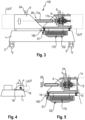
- the support distance u between two elastic elements 16 spaced apart in the direction of the axis 10 of the intermediate bearing shaft 5d is dimensioned such that a common center of gravity S of the bearing block 5 including all adapters and add-on parts X and the test element UUT is within the support distance u between the elastic and damping elements 16 must lie ( 4 ).
- the bearing block 5 consists of the intermediate bearing 5a, which consists of the bearing cartridge 5b, the bearings 5c, the intermediate bearing shaft 5d and the exchangeable flanges 5e, 5f as well as the sensors for temperature and vibration monitoring 5g ( 1 ).
- the replaceable flange 5e is positively connected via a spline 51 with the intermediate bearing shaft 5d.
- the flange 5e is axially prestressed against the intermediate bearing shaft 5d via a central screw 52, with an additional sleeve 53, preferably screwed in place, which presses balls 54 in a form-fitting manner against a groove 55, serving as a safeguard against loss.
- a braking device 6 is attached to the intermediate bearing 5a, which makes it possible to lock the drive train in any position in order to determine the breakaway torque depending on the position of the rotor relative to the stator of the electrical machine to be tested in the test unit UUT .
- a measuring flange 7 is mounted on the test unit-side flange 5f of the intermediate bearing 5, for example with a speed detection device equipped, which makes it possible to carry out an in-phase measurement of the mechanical power.
- a blocking device 18a acts on this flange 5f of the intermediate bearing 5 and is used to block the rotational movement when calibrating the measuring flange 7 .
- the adapter 8 for the stub shaft 9 leading to the test unit UUT is seated on the measuring flange 7.
- the connection to the stub shaft 9 is via a spline 10a with a defined installation position to enable a clear position to maintain the balancing quality.
- the adapter 8 is designed in such a way that, in addition to the stub shaft 9 for the test item, it can also accommodate a calibration device 18b and an alignment tool 12 (see Fig 2 , Figure 7, Figure 8 ).
- the stub shaft 9 for the test unit UUT has a receptacle for a motor shaft of the test unit UUT on the test unit UUT side.
- receptacles 11 are provided for balancing weights in order to improve the smooth running of the test unit UUT, if necessary.
- the design of the structure allows the vibration monitor 25 to determine the unbalance of the test unit UUT.
- adapter flange 14 between the testing unit UUT and the measuring and testing device 100 are provided both on the bearing block 5 and on an optional cooling adapter for climate chambers 15 adjustment devices. These allow alignment with the alignment tool 12 in the transverse and vertical directions.
- the intermediate bearing shaft 5d of the intermediate bearing 5a is connected to the dynamometer 3 by means of a universal joint shaft 26 and is electrically isolated from the dynamometer 3 by an electrical insulator--for example by an electrically non-conductive connecting tube 17a or an electrically insulating flange 17b.
- the damping elements 16 are held in insulating cups 19 in such a way that no electrically conductive contact occurs.
- a viscose or sand damper 170 is provided with a keel-shaped damping body 20 firmly connected to the bearing block 5 liquid damping material 22, such as sand or silicone oil, is movably mounted.
- the measuring and testing device 100 is equipped with vibration sensors 23 for linear and torsional vibrations in order to enable a detailed analysis of the behavior of both the measuring and testing device 100 and the testing unit UUT using an integrated data acquisition and evaluation unit 25 .
- warning lights 24 are attached, for example, to the highest point of the bearing block 5, which indicate the voltage state of both the testing unit UUT and the measuring and testing device 100.
- the measuring and testing device 100 can have a cooling device 200 with a first cooling circuit 201 .
- the first cooling circuit 201 of the measuring and testing device 100 and a second cooling circuit 202 of the test unit UUT can be electrically decoupled from one another.
- the first cooling circuit 201 of the measuring and testing device 100 is equipped with an intermediate circuit 203 for electrical insulation.
- This intermediate circuit 203 has a first heat exchanger 204 on the side of the first cooling circuit 201 of the measuring and testing device 100 and a second heat exchanger 205 on the side of the second cooling circuit 202 of the test unit UUT.
- These two heat exchangers 204, 205 are connected via lines 206 of the intermediate circuit 205, which consist of electrically non-conductive material.
- the intermediate circuit 203 is filled with a medium formed by a non-conductive dielectric that acts as a heat transfer medium.
- the medium is conveyed using a pump 207 .
- the flow and return temperatures are measured with thermocouples 208.
- the system pressure is controlled by a pressure sensor 209.
- the measuring and testing device 100 thus has a complete electrical and vibrational isolation from the test unit UUT to be tested and thus increases the reliability of the tests.
Landscapes
- Physics & Mathematics (AREA)
- General Physics & Mathematics (AREA)
- Testing Of Devices, Machine Parts, Or Other Structures Thereof (AREA)
Claims (13)
- Installation de mesure et de contrôle (100) pour une unité de test (UUT) notamment pour une machine électrique à rotation rapide avec un châssis intermédiaire (1) et au moins une poupée (5) pour un arbre de palier intermédiaire (5d) qui peut être relié dans le sens de l'entraînement à au moins une unité de test (UUT), la poupée (5) étant séparée galvaniquement du châssis intermédiaire (1),
installation caractérisée en ce que
la poupée (5) est reliée au châssis intermédiaire (1) par au moins un dispositif amortisseur (D1, D2), au moins un premier dispositif d'amortisseur (D1) étant réalisé comme amortisseur élastique (160) et au moins un second dispositif amortisseur (D2) est réalisé comme amortisseur à viscose ou sable (170). - Installation de mesure et de contrôle (100) selon la revendication 1, caractérisée en ce que
la poupée (5) est séparée galvaniquement du châssis intermédiaire (1) par au moins un dispositif amortisseur (D1, D2). - Installation de mesure et de contrôle (100) selon la revendication 1 ou 2,
caractérisée en ce que
l'amortisseur à viscose ou sable (170) comporte un récipient (21) rempli d'un matériau amortisseur (22), un corps d'amortisseur (20) étant installé dans le récipient (21) de manière mobile par rapport au récipient (21) dans le matériau amortisseur (22). - Installation de mesure et de contrôle (100) selon la revendication 3,
caractérisée en ce que
le récipient (21) est relié solidairement au châssis intermédiaire (1), de préférence le récipient (21) est intégré dans le châssis intermédiaire (1) ou est monté dans le châssis intermédiaire (1) ou sur le châssis intermédiaire (1). - Installation de mesure et de contrôle (100) selon la revendication 3 ou 4,
caractérisée en ce que
le matériau amortisseur (22) est une matière susceptible de couler de préférence du sable ou un fluide visqueux. - Installation de mesure et de contrôle (100) selon l'une des revendications 1 à 5,
caractérisée en ce queau moins un amortisseur élastique (160) comporte un élément amortisseur (16) élastique, relié solidairement de préférence à la poupée (5) et qui est logée dans une coupelle (19) reliée de préférence solidairement au châssis intermédiaire (1),l'élément amortisseur élastique (16) et/ou la coupelle (19) étant électroisolant. - Installation de mesure et de contrôle (100) selon la revendication 6, caractérisée en ce que
l'amortisseur élastique (160) comporte au moins deux éléments amortisseurs élastiques (16) qui, considérés dans la direction de l'axe (10) de l'arbre de palier intermédiaire (5d), à la distance d'appui (u) l'un de l'autre soutiennent l'arbre de palier intermédiaire (5d) de façon que le centre de gravité (S) de la poupée (5),- de préférence, y compris tous les composants, se situe à l'intérieur de la distance d'appui (u). - Installation de mesure et de contrôle (100) selon l'une des revendications 1 à 7,
caractérisée en ce que
l'arbre de palier intermédiaire (5d) de la poupée (5) est relié dans le sens de l'entraînement par un arbre de liaison (26) -de préférence réalisé comme arbre synchrone- est réalisé à un dynamomètre (3), une transmission multiplicatrice (3) ou un autre arbre de palier intermédiaire (5d') d'une autre poupée (5'), de préférence l'arbre de palier intermédiaire (5d) étant séparé galvaniquement par un isolateur électrique par rapport au dynamomètre (3), à la transmission multiplicatrice ou à l'autre arbre de palier intermédiaire (5d'). - Installation de mesure et de contrôle (100) selon la revendication 8,
caractérisée en ce que
l'isolateur électrique installé entre l'arbre de palier intermédiaire (5d) et le dynamomètre (3) est formé par un tube de liaison (17a) non électroconducteur ou par une bride (17b) non électro-conductrice. - Installation de mesure et de contrôle (100) selon l'une des revendications 1 à 9,
caractérisée par
une isolation acoustique et/ou thermique entre l'unité de test (UUT) et le palier intermédiaire (5a). - Installation de mesure et de contrôle (100) selon l'une des revendications 1 à 10,
caractérisée en ce que
l'installation de mesure et de contrôle (100) comporte une installation de refroidissement (200) avec un premier circuit de refroidissement (201) relié par une liaison thermique par au moins un échangeur de chaleur (204, 205) à un second circuit de refroidissement (201) de l'unité de test (UUT) de préférence, le premier circuit de refroidissement (201) est découplé électriquement du second circuit de refroidissement (202). - Installation de mesure et de contrôle (100) selon la revendication 11,
caractérisée en ce que
le premier circuit de refroidissement (201) est relié par une liasse thermique, par un premier échangeur (204), à un circuit intermédiaire (203), dont la conduite de refroidissement (206) est traversée par un milieu de refroidissement, le circuit intermédiaire (203) étant relié par une liaison thermique, par un second échangeur de chaleur (205) à un second circuit de refroidissement (201) de l'unité de test (UUT) de préférence, le milieu de refroidissement du circuit intermédiaire (203) est constitué par un diélectrique non-électroconducteur. - Installation de mesure et de contrôle (100) selon la revendication 11 ou 12,
caractérisée en ce que
au moins un segment de la conduite de refroidissement (206) du circuit intermédiaire (203) est en une matière non électro-conductrice.
Applications Claiming Priority (2)
| Application Number | Priority Date | Filing Date | Title |
|---|---|---|---|
| ATA50297/2020A AT523676B1 (de) | 2020-04-07 | 2020-04-07 | Mess- und prüfeinrichtung für schnelldrehende elektrische maschinen |
| PCT/AT2021/060101 WO2021203151A1 (fr) | 2020-04-07 | 2021-03-25 | Dispositif de mesure et de test pour machines électriques à rotation rapide |
Publications (2)
| Publication Number | Publication Date |
|---|---|
| EP4133250A1 EP4133250A1 (fr) | 2023-02-15 |
| EP4133250B1 true EP4133250B1 (fr) | 2023-06-14 |
Family
ID=75252254
Family Applications (1)
| Application Number | Title | Priority Date | Filing Date |
|---|---|---|---|
| EP21714620.8A Active EP4133250B1 (fr) | 2020-04-07 | 2021-03-25 | Dispositif de mesure et de test pour machines électriques à rotation rapide |
Country Status (5)
| Country | Link |
|---|---|
| EP (1) | EP4133250B1 (fr) |
| CN (1) | CN115427824A (fr) |
| AT (1) | AT523676B1 (fr) |
| ES (1) | ES2954849T3 (fr) |
| WO (1) | WO2021203151A1 (fr) |
Families Citing this family (2)
| Publication number | Priority date | Publication date | Assignee | Title |
|---|---|---|---|---|
| CN114705982A (zh) * | 2022-03-07 | 2022-07-05 | 中车唐山机车车辆有限公司 | 一种地铁列车牵引电机试验台 |
| DE102022118446A1 (de) | 2022-07-22 | 2024-01-25 | SINGLE Group GmbH | Temperiersystem mit Zwischenkreislauf |
Family Cites Families (17)
| Publication number | Priority date | Publication date | Assignee | Title |
|---|---|---|---|---|
| JP3488696B2 (ja) * | 2001-02-19 | 2004-01-19 | 丸和電機株式会社 | 高速回転試験装置 |
| CN2914104Y (zh) | 2006-05-22 | 2007-06-20 | 比亚迪股份有限公司 | 电动机试验装置 |
| DE102007036271A1 (de) * | 2007-07-31 | 2009-02-05 | Baumer Hübner GmbH | Drehgeber mit Überwachung des Lagerverschleißes sowie Verfahren hierzu |
| CN201218836Y (zh) | 2008-07-16 | 2009-04-08 | 泰豪科技股份有限公司 | 高速、重载、中小型发电机试验装置 |
| DE102010002296A1 (de) * | 2010-02-24 | 2011-08-25 | Siemens Aktiengesellschaft, 80333 | Auswertungsverfahren für Lichtbogenentladungen und zugehöriger Prüfstand |
| CN102621495A (zh) | 2012-03-09 | 2012-08-01 | 山东水星博惠汽车部件股份有限公司 | 一种汽车玻璃升降器电机快速逐检测试台 |
| CN104569810A (zh) | 2013-10-29 | 2015-04-29 | 北京精密机电控制设备研究所 | 一种高速电机负载试验系统 |
| EP3190397B1 (fr) | 2014-09-03 | 2020-02-12 | Horiba, Ltd.g | Système de test de moteur électrique |
| CN104635157B (zh) | 2015-01-20 | 2017-06-30 | 山东拓博节能科技有限公司 | 一种低转速大扭矩电机测试台 |
| CN104950255B (zh) | 2015-06-12 | 2019-02-01 | 山东省产品质量监督检验研究院 | 一种电动机负载装置 |
| CN106248382B (zh) | 2015-06-15 | 2018-11-27 | 北京富华惠航航空科技有限公司 | 起动机试验台 |
| CN105699081B (zh) * | 2016-01-21 | 2018-07-20 | 湖南科技大学 | 轴承轴电流损伤综合性能实验装置 |
| EP3242055B1 (fr) * | 2016-05-04 | 2019-06-19 | Caterpillar Energy Solutions GmbH | Indicateur d'usure d'amortisseur de vibrations |
| CN106291358A (zh) * | 2016-08-19 | 2017-01-04 | 无锡市朗迪测控技术有限公司 | 新能源电机测试台 |
| CN107246948B (zh) * | 2017-07-11 | 2019-04-12 | 哈尔滨工程大学 | 一种电机振动特征频率的检测装置及方法 |
| CN108303261A (zh) * | 2018-01-15 | 2018-07-20 | 武汉理工大学 | 一种基于激光测试技术的磁电式扭振减振器试验台架 |
| CN109061471B (zh) * | 2018-09-13 | 2023-09-08 | 安徽精科检测技术有限公司 | 电动汽车电机电磁兼容测功测试系统 |
-
2020
- 2020-04-07 AT ATA50297/2020A patent/AT523676B1/de active
-
2021
- 2021-03-25 EP EP21714620.8A patent/EP4133250B1/fr active Active
- 2021-03-25 WO PCT/AT2021/060101 patent/WO2021203151A1/fr not_active Ceased
- 2021-03-25 CN CN202180025810.0A patent/CN115427824A/zh active Pending
- 2021-03-25 ES ES21714620T patent/ES2954849T3/es active Active
Also Published As
| Publication number | Publication date |
|---|---|
| AT523676A1 (de) | 2021-10-15 |
| EP4133250A1 (fr) | 2023-02-15 |
| WO2021203151A1 (fr) | 2021-10-14 |
| ES2954849T3 (es) | 2023-11-27 |
| AT523676B1 (de) | 2022-01-15 |
| CN115427824A (zh) | 2022-12-02 |
Similar Documents
| Publication | Publication Date | Title |
|---|---|---|
| EP4133250B1 (fr) | Dispositif de mesure et de test pour machines électriques à rotation rapide | |
| DE60202750T2 (de) | Automatische ausgleichseinstellzentrifugalvorrichtung | |
| DE10206950B4 (de) | Hochgeschwindigkeitsrotationstestvorrichtung | |
| DE102007012586B3 (de) | Dentale Bearbeitungsmaschine | |
| DE3612038A1 (de) | Verfahren und vorrichtung zur messung von zaehigkeits- und elastizitaetskraeften | |
| EP0655617B1 (fr) | Banc d'essai pour véhicules avec un capteur de couple dans un rouleau | |
| DE102013101375B4 (de) | Gelenkwellen-Auswuchtmaschine und Auswuchtverfahren | |
| EP2057457A1 (fr) | Rhéomètre | |
| EP3899480B1 (fr) | Banc d'essai et procédé de vérification d'un palier | |
| DE102016116179A1 (de) | Werkzeugspindel mit Kraftmesseinrichtung | |
| CN103743565B (zh) | 角接触球轴承温度、轴向热位移测试装置及实验方法 | |
| DE3244464C2 (de) | Werkstoff- und Bauteil-Prüfmaschine | |
| EP0935751B1 (fr) | Procede pour determiner le pouvoir lubrifiant d'huiles lubrifiantes | |
| DE2645902B2 (de) | Einrichtung zur Reib- und VerschleißprUfung von Werkstoffproben | |
| DE102021205369B3 (de) | Prüfstand für einen Antriebsstrang eines Kraftfahrzeugs | |
| DE10113591C1 (de) | Prüfeinrichtung zur Untersuchung des Verhaltens von Wellendichtsystemen | |
| WO2006099641A1 (fr) | Ensemble servant a etalonner un capteur de couple | |
| DE102018102327A1 (de) | Kraftmesseinrichtung zur Erfassung von Bearbeitungskräften an einer Werkzeugmaschine sowie Werkzeugmaschine mit Kraftmesseinrichtung | |
| WO2019121689A1 (fr) | Dispositif et procédé de détermination d'une grandeur d'état | |
| EP2270487B1 (fr) | Dispositif de contrôle par ultrasons d'arbres d'essieux montés sur des wagons de transport de marchandises | |
| DE2701876C3 (de) | Vorrichtung zum Messen der Unwuchten von Rotoren, insbesondere von Fahrzeugrädern | |
| EP4508406B1 (fr) | Unité d'entraînement pour banc d'essai de train d'entraînement pour tester un train d'entraînement de véhicule à moteur, et banc d'essai de train d'entraînement | |
| EP1601944A1 (fr) | Procede et dispositif pour equilibrer des rotors sans tourillon | |
| AT527595B1 (de) | Vorrichtung und Verfahren zum Prüfen einer rotierenden elektrischen Maschine | |
| DE102008062255A1 (de) | Wuchtvorrichtung mit Zusatzlager |
Legal Events
| Date | Code | Title | Description |
|---|---|---|---|
| STAA | Information on the status of an ep patent application or granted ep patent |
Free format text: STATUS: UNKNOWN |
|
| STAA | Information on the status of an ep patent application or granted ep patent |
Free format text: STATUS: THE INTERNATIONAL PUBLICATION HAS BEEN MADE |
|
| PUAI | Public reference made under article 153(3) epc to a published international application that has entered the european phase |
Free format text: ORIGINAL CODE: 0009012 |
|
| STAA | Information on the status of an ep patent application or granted ep patent |
Free format text: STATUS: REQUEST FOR EXAMINATION WAS MADE |
|
| 17P | Request for examination filed |
Effective date: 20220829 |
|
| AK | Designated contracting states |
Kind code of ref document: A1 Designated state(s): AL AT BE BG CH CY CZ DE DK EE ES FI FR GB GR HR HU IE IS IT LI LT LU LV MC MK MT NL NO PL PT RO RS SE SI SK SM TR |
|
| GRAP | Despatch of communication of intention to grant a patent |
Free format text: ORIGINAL CODE: EPIDOSNIGR1 |
|
| STAA | Information on the status of an ep patent application or granted ep patent |
Free format text: STATUS: GRANT OF PATENT IS INTENDED |
|
| INTG | Intention to grant announced |
Effective date: 20230216 |
|
| GRAS | Grant fee paid |
Free format text: ORIGINAL CODE: EPIDOSNIGR3 |
|
| GRAA | (expected) grant |
Free format text: ORIGINAL CODE: 0009210 |
|
| STAA | Information on the status of an ep patent application or granted ep patent |
Free format text: STATUS: THE PATENT HAS BEEN GRANTED |
|
| AK | Designated contracting states |
Kind code of ref document: B1 Designated state(s): AL AT BE BG CH CY CZ DE DK EE ES FI FR GB GR HR HU IE IS IT LI LT LU LV MC MK MT NL NO PL PT RO RS SE SI SK SM TR |
|
| DAV | Request for validation of the european patent (deleted) | ||
| DAX | Request for extension of the european patent (deleted) | ||
| REG | Reference to a national code |
Ref country code: CH Ref legal event code: EP |
|
| P01 | Opt-out of the competence of the unified patent court (upc) registered |
Effective date: 20230515 |
|
| REG | Reference to a national code |
Ref country code: DE Ref legal event code: R096 Ref document number: 502021000882 Country of ref document: DE |
|
| REG | Reference to a national code |
Ref country code: AT Ref legal event code: REF Ref document number: 1579566 Country of ref document: AT Kind code of ref document: T Effective date: 20230715 |
|
| REG | Reference to a national code |
Ref country code: LT Ref legal event code: MG9D |
|
| REG | Reference to a national code |
Ref country code: NL Ref legal event code: MP Effective date: 20230614 |
|
| PG25 | Lapsed in a contracting state [announced via postgrant information from national office to epo] |
Ref country code: SE Free format text: LAPSE BECAUSE OF FAILURE TO SUBMIT A TRANSLATION OF THE DESCRIPTION OR TO PAY THE FEE WITHIN THE PRESCRIBED TIME-LIMIT Effective date: 20230614 Ref country code: NO Free format text: LAPSE BECAUSE OF FAILURE TO SUBMIT A TRANSLATION OF THE DESCRIPTION OR TO PAY THE FEE WITHIN THE PRESCRIBED TIME-LIMIT Effective date: 20230914 |
|
| REG | Reference to a national code |
Ref country code: ES Ref legal event code: FG2A Ref document number: 2954849 Country of ref document: ES Kind code of ref document: T3 Effective date: 20231127 |
|
| PG25 | Lapsed in a contracting state [announced via postgrant information from national office to epo] |
Ref country code: RS Free format text: LAPSE BECAUSE OF FAILURE TO SUBMIT A TRANSLATION OF THE DESCRIPTION OR TO PAY THE FEE WITHIN THE PRESCRIBED TIME-LIMIT Effective date: 20230614 Ref country code: NL Free format text: LAPSE BECAUSE OF FAILURE TO SUBMIT A TRANSLATION OF THE DESCRIPTION OR TO PAY THE FEE WITHIN THE PRESCRIBED TIME-LIMIT Effective date: 20230614 Ref country code: LV Free format text: LAPSE BECAUSE OF FAILURE TO SUBMIT A TRANSLATION OF THE DESCRIPTION OR TO PAY THE FEE WITHIN THE PRESCRIBED TIME-LIMIT Effective date: 20230614 Ref country code: LT Free format text: LAPSE BECAUSE OF FAILURE TO SUBMIT A TRANSLATION OF THE DESCRIPTION OR TO PAY THE FEE WITHIN THE PRESCRIBED TIME-LIMIT Effective date: 20230614 Ref country code: HR Free format text: LAPSE BECAUSE OF FAILURE TO SUBMIT A TRANSLATION OF THE DESCRIPTION OR TO PAY THE FEE WITHIN THE PRESCRIBED TIME-LIMIT Effective date: 20230614 Ref country code: GR Free format text: LAPSE BECAUSE OF FAILURE TO SUBMIT A TRANSLATION OF THE DESCRIPTION OR TO PAY THE FEE WITHIN THE PRESCRIBED TIME-LIMIT Effective date: 20230915 |
|
| PG25 | Lapsed in a contracting state [announced via postgrant information from national office to epo] |
Ref country code: FI Free format text: LAPSE BECAUSE OF FAILURE TO SUBMIT A TRANSLATION OF THE DESCRIPTION OR TO PAY THE FEE WITHIN THE PRESCRIBED TIME-LIMIT Effective date: 20230614 |
|
| PG25 | Lapsed in a contracting state [announced via postgrant information from national office to epo] |
Ref country code: SK Free format text: LAPSE BECAUSE OF FAILURE TO SUBMIT A TRANSLATION OF THE DESCRIPTION OR TO PAY THE FEE WITHIN THE PRESCRIBED TIME-LIMIT Effective date: 20230614 |
|
| PG25 | Lapsed in a contracting state [announced via postgrant information from national office to epo] |
Ref country code: IS Free format text: LAPSE BECAUSE OF FAILURE TO SUBMIT A TRANSLATION OF THE DESCRIPTION OR TO PAY THE FEE WITHIN THE PRESCRIBED TIME-LIMIT Effective date: 20231014 |
|
| PG25 | Lapsed in a contracting state [announced via postgrant information from national office to epo] |
Ref country code: SM Free format text: LAPSE BECAUSE OF FAILURE TO SUBMIT A TRANSLATION OF THE DESCRIPTION OR TO PAY THE FEE WITHIN THE PRESCRIBED TIME-LIMIT Effective date: 20230614 Ref country code: SK Free format text: LAPSE BECAUSE OF FAILURE TO SUBMIT A TRANSLATION OF THE DESCRIPTION OR TO PAY THE FEE WITHIN THE PRESCRIBED TIME-LIMIT Effective date: 20230614 Ref country code: RO Free format text: LAPSE BECAUSE OF FAILURE TO SUBMIT A TRANSLATION OF THE DESCRIPTION OR TO PAY THE FEE WITHIN THE PRESCRIBED TIME-LIMIT Effective date: 20230614 Ref country code: PT Free format text: LAPSE BECAUSE OF FAILURE TO SUBMIT A TRANSLATION OF THE DESCRIPTION OR TO PAY THE FEE WITHIN THE PRESCRIBED TIME-LIMIT Effective date: 20231016 Ref country code: IS Free format text: LAPSE BECAUSE OF FAILURE TO SUBMIT A TRANSLATION OF THE DESCRIPTION OR TO PAY THE FEE WITHIN THE PRESCRIBED TIME-LIMIT Effective date: 20231014 Ref country code: EE Free format text: LAPSE BECAUSE OF FAILURE TO SUBMIT A TRANSLATION OF THE DESCRIPTION OR TO PAY THE FEE WITHIN THE PRESCRIBED TIME-LIMIT Effective date: 20230614 Ref country code: CZ Free format text: LAPSE BECAUSE OF FAILURE TO SUBMIT A TRANSLATION OF THE DESCRIPTION OR TO PAY THE FEE WITHIN THE PRESCRIBED TIME-LIMIT Effective date: 20230614 |
|
| PG25 | Lapsed in a contracting state [announced via postgrant information from national office to epo] |
Ref country code: PL Free format text: LAPSE BECAUSE OF FAILURE TO SUBMIT A TRANSLATION OF THE DESCRIPTION OR TO PAY THE FEE WITHIN THE PRESCRIBED TIME-LIMIT Effective date: 20230614 |
|
| REG | Reference to a national code |
Ref country code: DE Ref legal event code: R097 Ref document number: 502021000882 Country of ref document: DE |
|
| PLBE | No opposition filed within time limit |
Free format text: ORIGINAL CODE: 0009261 |
|
| STAA | Information on the status of an ep patent application or granted ep patent |
Free format text: STATUS: NO OPPOSITION FILED WITHIN TIME LIMIT |
|
| PG25 | Lapsed in a contracting state [announced via postgrant information from national office to epo] |
Ref country code: DK Free format text: LAPSE BECAUSE OF FAILURE TO SUBMIT A TRANSLATION OF THE DESCRIPTION OR TO PAY THE FEE WITHIN THE PRESCRIBED TIME-LIMIT Effective date: 20230614 |
|
| PG25 | Lapsed in a contracting state [announced via postgrant information from national office to epo] |
Ref country code: SI Free format text: LAPSE BECAUSE OF FAILURE TO SUBMIT A TRANSLATION OF THE DESCRIPTION OR TO PAY THE FEE WITHIN THE PRESCRIBED TIME-LIMIT Effective date: 20230614 |
|
| 26N | No opposition filed |
Effective date: 20240315 |
|
| PG25 | Lapsed in a contracting state [announced via postgrant information from national office to epo] |
Ref country code: SI Free format text: LAPSE BECAUSE OF FAILURE TO SUBMIT A TRANSLATION OF THE DESCRIPTION OR TO PAY THE FEE WITHIN THE PRESCRIBED TIME-LIMIT Effective date: 20230614 Ref country code: IT Free format text: LAPSE BECAUSE OF FAILURE TO SUBMIT A TRANSLATION OF THE DESCRIPTION OR TO PAY THE FEE WITHIN THE PRESCRIBED TIME-LIMIT Effective date: 20230614 |
|
| REG | Reference to a national code |
Ref country code: CH Ref legal event code: PL |
|
| PG25 | Lapsed in a contracting state [announced via postgrant information from national office to epo] |
Ref country code: BG Free format text: LAPSE BECAUSE OF FAILURE TO SUBMIT A TRANSLATION OF THE DESCRIPTION OR TO PAY THE FEE WITHIN THE PRESCRIBED TIME-LIMIT Effective date: 20230614 |
|
| PG25 | Lapsed in a contracting state [announced via postgrant information from national office to epo] |
Ref country code: LU Free format text: LAPSE BECAUSE OF NON-PAYMENT OF DUE FEES Effective date: 20240325 |
|
| PG25 | Lapsed in a contracting state [announced via postgrant information from national office to epo] |
Ref country code: MC Free format text: LAPSE BECAUSE OF FAILURE TO SUBMIT A TRANSLATION OF THE DESCRIPTION OR TO PAY THE FEE WITHIN THE PRESCRIBED TIME-LIMIT Effective date: 20230614 |
|
| PG25 | Lapsed in a contracting state [announced via postgrant information from national office to epo] |
Ref country code: MC Free format text: LAPSE BECAUSE OF FAILURE TO SUBMIT A TRANSLATION OF THE DESCRIPTION OR TO PAY THE FEE WITHIN THE PRESCRIBED TIME-LIMIT Effective date: 20230614 Ref country code: LU Free format text: LAPSE BECAUSE OF NON-PAYMENT OF DUE FEES Effective date: 20240325 Ref country code: BG Free format text: LAPSE BECAUSE OF FAILURE TO SUBMIT A TRANSLATION OF THE DESCRIPTION OR TO PAY THE FEE WITHIN THE PRESCRIBED TIME-LIMIT Effective date: 20230614 |
|
| REG | Reference to a national code |
Ref country code: BE Ref legal event code: MM Effective date: 20240331 |
|
| PG25 | Lapsed in a contracting state [announced via postgrant information from national office to epo] |
Ref country code: BE Free format text: LAPSE BECAUSE OF NON-PAYMENT OF DUE FEES Effective date: 20240331 |
|
| PG25 | Lapsed in a contracting state [announced via postgrant information from national office to epo] |
Ref country code: IE Free format text: LAPSE BECAUSE OF NON-PAYMENT OF DUE FEES Effective date: 20240325 |
|
| PG25 | Lapsed in a contracting state [announced via postgrant information from national office to epo] |
Ref country code: IE Free format text: LAPSE BECAUSE OF NON-PAYMENT OF DUE FEES Effective date: 20240325 Ref country code: BE Free format text: LAPSE BECAUSE OF NON-PAYMENT OF DUE FEES Effective date: 20240331 Ref country code: CH Free format text: LAPSE BECAUSE OF NON-PAYMENT OF DUE FEES Effective date: 20240331 |
|
| PGFP | Annual fee paid to national office [announced via postgrant information from national office to epo] |
Ref country code: AT Payment date: 20250417 Year of fee payment: 5 |
|
| PGFP | Annual fee paid to national office [announced via postgrant information from national office to epo] |
Ref country code: ES Payment date: 20250429 Year of fee payment: 5 |
|
| PG25 | Lapsed in a contracting state [announced via postgrant information from national office to epo] |
Ref country code: CY Free format text: LAPSE BECAUSE OF FAILURE TO SUBMIT A TRANSLATION OF THE DESCRIPTION OR TO PAY THE FEE WITHIN THE PRESCRIBED TIME-LIMIT; INVALID AB INITIO Effective date: 20210325 |
|
| PG25 | Lapsed in a contracting state [announced via postgrant information from national office to epo] |
Ref country code: HU Free format text: LAPSE BECAUSE OF FAILURE TO SUBMIT A TRANSLATION OF THE DESCRIPTION OR TO PAY THE FEE WITHIN THE PRESCRIBED TIME-LIMIT; INVALID AB INITIO Effective date: 20210325 |
|
| PG25 | Lapsed in a contracting state [announced via postgrant information from national office to epo] |
Ref country code: TR Free format text: LAPSE BECAUSE OF FAILURE TO SUBMIT A TRANSLATION OF THE DESCRIPTION OR TO PAY THE FEE WITHIN THE PRESCRIBED TIME-LIMIT Effective date: 20230614 |
|
| PGFP | Annual fee paid to national office [announced via postgrant information from national office to epo] |
Ref country code: GB Payment date: 20260324 Year of fee payment: 6 |
|
| PGFP | Annual fee paid to national office [announced via postgrant information from national office to epo] |
Ref country code: DE Payment date: 20260319 Year of fee payment: 6 |
|
| PGFP | Annual fee paid to national office [announced via postgrant information from national office to epo] |
Ref country code: FR Payment date: 20260323 Year of fee payment: 6 |