EP4133573B1 - Haltesystem für stromschienen an statoren bzw. statorsegmenten dynamoelektrischer maschinen - Google Patents
Haltesystem für stromschienen an statoren bzw. statorsegmenten dynamoelektrischer maschinen Download PDFInfo
- Publication number
- EP4133573B1 EP4133573B1 EP21708125.6A EP21708125A EP4133573B1 EP 4133573 B1 EP4133573 B1 EP 4133573B1 EP 21708125 A EP21708125 A EP 21708125A EP 4133573 B1 EP4133573 B1 EP 4133573B1
- Authority
- EP
- European Patent Office
- Prior art keywords
- stator
- bus bars
- elements
- busbars
- fixed
- Prior art date
- Legal status (The legal status is an assumption and is not a legal conclusion. Google has not performed a legal analysis and makes no representation as to the accuracy of the status listed.)
- Active
Links
Images


Classifications
-
- H—ELECTRICITY
- H02—GENERATION; CONVERSION OR DISTRIBUTION OF ELECTRIC POWER
- H02K—DYNAMO-ELECTRIC MACHINES
- H02K3/00—Details of windings
- H02K3/46—Fastening of windings on the stator or rotor structure
- H02K3/50—Fastening of winding heads, equalising connectors, or connections thereto
- H02K3/505—Fastening of winding heads, equalising connectors, or connections thereto for large machine windings, e.g. bar windings
-
- H—ELECTRICITY
- H02—GENERATION; CONVERSION OR DISTRIBUTION OF ELECTRIC POWER
- H02K—DYNAMO-ELECTRIC MACHINES
- H02K7/00—Arrangements for handling mechanical energy structurally associated with dynamo-electric machines, e.g. structural association with mechanical driving motors or auxiliary dynamo-electric machines
- H02K7/18—Structural association of electric generators with mechanical driving motors, e.g. with turbines
- H02K7/1807—Rotary generators
- H02K7/1823—Rotary generators structurally associated with turbines or similar engines
- H02K7/183—Rotary generators structurally associated with turbines or similar engines wherein the turbine is a wind turbine
-
- H—ELECTRICITY
- H02—GENERATION; CONVERSION OR DISTRIBUTION OF ELECTRIC POWER
- H02K—DYNAMO-ELECTRIC MACHINES
- H02K2203/00—Specific aspects not provided for in the other groups of this subclass relating to the windings
- H02K2203/09—Machines characterised by wiring elements other than wires, e.g. bus rings, for connecting the winding terminations
-
- Y—GENERAL TAGGING OF NEW TECHNOLOGICAL DEVELOPMENTS; GENERAL TAGGING OF CROSS-SECTIONAL TECHNOLOGIES SPANNING OVER SEVERAL SECTIONS OF THE IPC; TECHNICAL SUBJECTS COVERED BY FORMER USPC CROSS-REFERENCE ART COLLECTIONS [XRACs] AND DIGESTS
- Y02—TECHNOLOGIES OR APPLICATIONS FOR MITIGATION OR ADAPTATION AGAINST CLIMATE CHANGE
- Y02E—REDUCTION OF GREENHOUSE GAS [GHG] EMISSIONS, RELATED TO ENERGY GENERATION, TRANSMISSION OR DISTRIBUTION
- Y02E10/00—Energy generation through renewable energy sources
- Y02E10/70—Wind energy
- Y02E10/72—Wind turbines with rotation axis in wind direction
Definitions
- the invention relates to a holding system for busbars on stators or stator segments of dynamoelectric machines, in particular wind power generators, as well as to such a stator of a dynamoelectric machine and a wind turbine.
- Coils especially those of larger dynamoelectric machines, are electrically combined in coil groups or coil systems. This usually requires busbars, which, due to their increased weight, can no longer be attached directly to the winding heads. In wind turbines, especially in directly driven wind power generators, massive busbars are usually used, which further increase the weight problem.
- busbars of a directly driven wind turbine generator which is constructed in segments, are known, for example, from WO 2019/185224 A1 known.
- a stator with several coils lying one above the other is known, with each coil having two coil sides with ends protruding axially from the stator, which are connected to one another on the head side of the stator by a C-shaped connecting ring.
- Holding elements are provided which are screwed to the head side of the stator, with several receptacles for connecting rings being formed on the holding elements by means of spacers.
- the spacers are made of an insulating material.
- a holder for busbars on a press plate of a stator is known in which the busbars are clamped between a spacer block, angle pieces and a holder piece with initially deformable padding in between.
- the padding adapts to the shape of the busbars and is then hardened.
- the invention is based on the object of creating a holding system that is suitable for busbars of a dynamoelectric machine, in particular for a directly driven generator of a wind turbine.
- the required insulation strength/insulation distances of these busbars should be maintained within this holding system, and sufficient cooling should be provided for the busbars and the dynamoelectric machine.
- the holding system should be integrated into the structure of the dynamoelectric machine as far as possible in order to provide a compact generator in a nacelle of a wind turbine.
- a holding system for busbars with the following elements: a base element that can be fastened to a front side of a stator or stator segment of a dynamoelectric machine and a predetermined number of fixing elements by means of which the busbars can be fixed to the base element.
- the task can also be solved by a generator of a wind turbine with a stator or stator segment.
- the task can also be solved using a wind turbine with a generator.
- the holding system according to the invention which is made in particular from steel, means that fastening-relevant, load-bearing holes can now be made directly in the base elements and fixing elements. Additional fixing components can be omitted and the assembly effort is made much easier. This increases the rigidity of the holding system, in particular its components such as the base element and fixing elements, so that the entire connection surfaces for busbars are subject to less vibration.
- the course of the busbars on the front side of the stator or stator segment can thus also be optimized with regard to the required insulation distances, so that an optimized design of the dimensions of the holding system benefits the ventilation of the winding head of the stator.
- the arrangement of the busbars represents the respective supply line to a phase of a coil group of the winding system of the dynamoelectric machine, in particular the generator.
- Electrical contact between the busbars in the circumferential direction can be achieved by plugging them together, welding them or using stranded wire connections.
- Data cables can also be easily installed on the holding system by attaching them to the holding system with cable ties.
- the holding system with its busbars, star point connections, grounding lines and data lines is essentially arranged radially under the winding head of a stator segment or the stator. This leads to a more compact structure. This structure also enables the busbars to be integrated into a possible cooling arrangement of the winding heads.
- stator segment with a ready-to-use winding system and pre-assembled busbars on the stator segment enables almost complete factory-tested pre-assembly, which reduces the assembly time on the system side.
- FIG 1 shows a holding system 1, according to claim 1, which is basically made up of a base element 2 and fixing elements 3 made of steel. These base elements 2 are fastened to a pressure plate 16 by means of screw connections 4 when installed. The fixing elements 3 are fastened to the respective base element 2 when installed. The fixing elements 3 have feet 10 in order to enclose a cam 9 of the base element 2, wherein an asymmetrically arranged bore 8 ensures that confusion of the installation position of the fixing elements 3 is excluded.
- the holding system 1 When the holding system 1 is assembled, there are now installation spaces 6 for the busbars 7 and, if necessary, for star point connections or earthing lines. When assembled, the holding system 1 has openings 5. This suppresses eddy currents when the busbars 7 are energized, since there are no closed metallic connections between the individual elements.
- FIG 2 shows in a partial perspective view the arrangement of the busbars 7 within the holding system 1, wherein the holding system 1 is attached to the pressure plates 16 of a stator 22 or a stator segment 13.
- the busbars 7 In the area of the base element 2 and the fixing elements 3, the busbars 7 have insulation elements 12, which have different thicknesses depending on the applied voltage.
- FIG 3 shows an example of a stator segment 13 in perspective, but not to scale, with holding system 1, but without busbars 7, whereby the laminated core 14 is constructed in the axial direction from partial laminated cores.
- the laminated core 14 is limited and fixed in the axial direction by pressure plates 16, whereby connecting elements 17 hold the pressure plates 16 together on the front sides of the stator segment 13.
- Form coils 18 are arranged in grooves of the laminated core 14 (not shown in detail), the winding heads of which have different offsets. Electrical energy is now supplied to or discharged from these form coils 18. This takes place via the busbars 7, which are positioned on the front side of the holding system 1, in particular on the pressure plates 16.
- the busbars 7 extend over the entire circumferential width of a stator segment 13, thus corresponding approximately to the length of the pressure plate 16. Depending on the type of connection to the circumferentially adjacent stator segments, the busbars 7 can be longer or shorter.
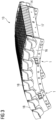
- FIG 4 shows a basic representation of a stator 22 which is constructed from stator segments 13, wherein the respective coils 18 or coil groups of each stator segment 13 are contacted via this busbar system from a holding system 1 which has three busbars 7.
- the busbars 7 are curved and essentially follow the radius of the stator 22. Each stator segment 13 can thereby accommodate its already positioned in the holding system 1 busbars 7. When assembling the stator segments 13 to form a stator 22, the respective busbars 7 are subsequently contacted.
- busbar sections are also possible that extend over two, three or more segments in the circumferential direction. Quarter circles or even semicircles are therefore possible.
- the electrical connecting lines 20 must be adapted accordingly.
- Contact elements 21 are used to establish electrical contact between busbar sections of a phase. Such electrical contact between the busbar sections in the circumferential direction can be achieved by plugging them together, welding them, using stranded wire connections, etc.
- the compact structure can now be sufficiently cooled by fans through appropriately guided air flows over or through the laminated core 14, as well as in the area of the winding heads and the busbars 7.
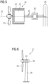
- FIG 5 shows a basic arrangement of a directly driven generator 24 of a wind turbine 27, wherein the rotation of the wind turbine 25 drives a rotor 23 which generates electrical energy through electromagnetic interaction with a winding system of the stator 22, which is made available to a supply network 26 via a converter unit 30.
- Such an arrangement is used, for example, in wind turbines 27 according to FIG 6 to be provided, a generator 24 is arranged in a nacelle 29 on a tower 28.
Landscapes
- Engineering & Computer Science (AREA)
- Power Engineering (AREA)
- Life Sciences & Earth Sciences (AREA)
- Sustainable Development (AREA)
- Sustainable Energy (AREA)
- Windings For Motors And Generators (AREA)
- Iron Core Of Rotating Electric Machines (AREA)
- Motor Or Generator Frames (AREA)
- Insulation, Fastening Of Motor, Generator Windings (AREA)
Description
- Die Erfindung betrifft ein Haltesystem für Stromschienen an Statoren bzw. Statorsegmenten dynamoelektrischer Maschinen, insbesondere Windkraftgeneratoren, als auch einen derartigen Stator einer dynamoelektrischen Maschine und eine Windkraftanlage.
- Spulen, insbesondere größerer dynamoelektrischer Maschinen werden in Spulengruppen oder Spulensystemen elektrisch zusammengefasst. Dazu wurden in der Regel Stromschienen benötigt, welche bei erhöhtem Eigengewicht nicht mehr direkt an den Wickelköpfen befestigt werden können. Bei Windkraftanlagen, speziell bei direkt angetriebenen Windkraftgeneratoren, werden üblicherweise massive Stromschienen verwendet, die die Eigengewichtsproblematik zusätzlich erhöhen.
- Derartige Stromschienen eines direkt angetriebenen Windkraftgenerators, der segmentiert aufgebaut ist, sind beispielsweise aus der
WO 2019/185224 A1 bekannt. - Aus
US 4 321 497 A ist ein Stator mit mehreren übereinander liegenden Spulen bekannt, wobei eine jeweilige Spule zwei Spulenseiten mit axial aus dem Stator herausragenden Enden aufweist, die kopfseitig des Stators durch einen C-förmigen Verbindungsring miteinander verbunden sind. Dabei sind Halteelemente vorgesehen, die kopfseitig an dem Stator angeschraubt sind, wobei an den Halteelementen mittels Spacern mehrere Aufnahmen für Verbindungsringe ausgebildet sind. Die Spacer sind aus einem isolierenden Material gebildet. - Aus
DE 2 161 139 A1 ist eine elastische Wickelkopfabstützung bekannt, bei der Spulen axial beweglich gegenüber dem Stator gehalten sind. - Aus
CN 106 253 538 A ist ein Halteelement für einen elektrisch leitenden Ring an einem Stator bekannt. - Aus
US 3 348 085 A ist eine Abstützung für Statorwicklungen bekannt. - Aus
EP 0 375 419 A2 ist ferner eine Leiterringanordnung für eine dynamoelektrische Maschine bekannt. - Aus
DE 1 200 932 A ist ein Halterung für Sammelschienen an einer Pressplatte eines Stators bekannt, bei der die Sammelschienen zwischen einem Abstandsblock, Winkelstücken und einem Halterungsstück mit dazwischenliegenden, zunächst verformbaren Polsterungen geklemmt werden. Die Polsterungen passen sich dabei der Form der Sammelschienen an und werden anschließend ausgehärtet. - Ausgehend davon liegt der Erfindung die Aufgabe zugrunde, ein Haltesystem zu schaffen, das für Stromschienen einer dynamoelektrischen Maschine, insbesondere für einen direkt angetriebenen Generator einer Windkraftanlage geeignet ist. Dabei soll vor allem die erforderliche Isolationsfestigkeit/Isolationsabstände dieser Stromschienen innerhalb dieses Haltesystems eingehalten werden, als auch für eine ausreichende Kühlmöglichkeit für die Stromschienen und die dynamoelektrische Maschine gesorgt werden. Des Weiteren soll das Haltesystem möglichst in den Aufbau der dynamoelektrischen Maschine integriert sein, um einen kompakten Generator in einer Gondel einer Windkraftanlage bereitzustellen.
- Die Lösung der gestellten Aufgabe gelingt durch ein Haltesystem von Stromschienen mit folgenden Elementen: einem Grundelement an einer Stirnseite eines Stators oder Statorsegments einer dynamoelektrischen Maschine befestigbar und einer vorgegebenen Anzahl von Fixierelementen mittels derer die Stromschienen am Grundelement fixierbar sind.
- Die Lösung der gestellten Aufgabe gelingt ebenso durch einen Stator bzw. Statorsegment einer dynamoelektrischen Maschine,
- wobei dort im Wesentlichen axial verlaufenden Nuten eines Blechpaketes ein Wicklungssystem vorgesehen ist, dass an den Stirnseiten Wickelköpfe ausbildet,
- wobei das Blechpaket auf einem Trägersystem angeordnet ist, das Druckplatten im Bereich der Stirnseite aufweist, die mittels Verbindungselemente fixiert sind,
- wobei ein Haltesystem von Stromschienen nach Anspruch 1 vorgesehen ist, das mit einem Grundelement an einer Stirnseite eines Stators oder Statorsegments der dynamoelektrischen Maschine befestigbar ist und Stromschienen mittels einer vorgegebenen Anzahl von Fixierelementen am Grundelement fixierbar sind.
- Die Lösung der gestellten Aufgabe gelingt ebenso durch einen Generator einer Windkraftanlage mit Stator oder Statorsegment.
- Die Lösung der gestellten Aufgabe gelingt ebenso durch eine Windkraftanlage mit einem Generator.
- Durch das erfindungsgemäße Haltesystem, dass insbesondere durch Stahl realisiert ist, können nun befestigungsrelevante belastbare Bohrungen direkt in die Grundelemente und Fixierelemente eingebracht werden. Zusätzliche Fixierkomponenten können dabei entfallen und der Montageaufwand wird dabei wesentlich vereinfacht. Dadurch erhöht sich die Steifigkeit des Haltesystems, insbesondere seiner Komponenten wie Grundelement und Fixierelementen, so dass die gesamten Anschlussflächen für Stromschienen schwingungsärmer sind.
- Der Verlauf der Stromschienen an der Stirnseite des Stators bzw. Statorsegments kann damit auch hinsichtlich der erforderlichen Isolationsstrecken optimiert werden, so dass eine optimierte Ausführung der Dimensionen des Haltesystems der Belüftung des Wickelkopfes des Stators zu Gute kommt.
- Die Anordnung der Stromschienen stellen die jeweilige Zuleitung zu einer Phase einer Spulengruppe des Wicklungssystems der dynamoelektrischen Maschine, insbesondere des Generators dar.
- Eine elektrische Kontaktierung der Stromschienen in Umfangsrichtung kann durch Zusammenstecken, verschweißen, Litzenverbindungen erfolgen.
- Um eine weitere Gewichtsreduzierung der Stromschienen zu erhalten, können diese bezüglich ihres Querschnitts ausgehend vom Einspeisepunkt reduziert werden.
- Am Haltesystem können ebenso in einfacher Art und Weise Datenleitungen mit verlegt werden, indem diese mit Kabelbinder am Haltesystem befestigt werden.
- Das Haltesystem mit seinen Stromschienen, Sternpunktverbindungen, Erdungsleitungen und Datenleitungen ist im Wesentlichen radial unter dem Wickelkopf eines Statorsegments oder des Stators angeordnet. Dies führt zu einem kompakteren Aufbau. Dieser Aufbau ermöglicht auch die Einbindung der Stromschienen in eine eventuelle Kühlanordnung der Wickelköpfe.
- Das Statorsegment mit funktionsfertigem Wicklungssystem, vormontierter Stromschienen am Statorsegment ermöglicht eine fast komplette werksseitige, und damit geprüfte Vormontage, die die anlagenseitige Montagezeit reduziert.
- Mittels der Anordnung der Stromschienen an der Stirnseite des Stators lässt sich ein kompakter Aufbau der dynamoelektrischen Maschine, insbesondere eines Generators einer Windkraftanlage bereitstellen.
- Damit ist ein kompakter Aufbau dieses Generators bei gleichzeitig ausreichender Belüftung seines Wicklungssystems und der Stromschienen möglich.
- Die Erfindung sowie weitere vorteilhafte Ausgestaltungen der Erfindung werden anhand prinzipiell dargestellter Ausführungsbeispiele näher erläutert, darin zeigen:
- FIG 1
- Elemente des Haltesystems,
- FIG 2
- perspektivische Darstellung von Stromschienen im Haltesystem,
- FIG 3
- Statorsegment
- FIG 4
- prinzipieller Anordnung von Statorsegmenten,
- FIG 5
- direkt angetriebener Generator,
- FIG 6
- Windkraftanlage.
-
FIG 1 zeigt ein Haltesystem 1, gemäss Anspruch 1, das grundsätzlich aus einem Grundelement 2 und Fixierelementen 3 aus Stahl aufgebaut ist. Diese Grundelemente 2 sind im eingebauten Zustand mittels Schraubverbindungen 4 an einer Druckplatte 16 befestigt. Die Fixierelemente 3 sind im eingebauten Zustand am jeweiligen Grundelement 2 befestigt. Die Fixierelemente 3 weisen Füße 10 auf, um einen Nocken 9 des Grundelements 2 zu umfassen, wobei durch eine asymmetrisch angeordnete Bohrung 8 gewährleistet ist, dass eine Verwechslung der Einbaulage der Fixierelemente 3 ausgeschlossen ist. - Im zusammengebauten Zustand des Haltesystems 1 ergeben sich nunmehr Bauräume 6 für die Stromschienen 7, als auch gegebenenfalls für Sternpunktverbindungen oder Erdungsleitungen. Im zusammengebauten Zustand weist das Haltesystem 1 Öffnungen 5 auf. Damit werden bei bestromten Stromschienen 7 Wirbelströme unterdrückt, da keine geschlossenen metallischen Verbindungen zwischen den Einzelelementen vorhanden sind.
-
FIG 2 zeigt in einer teilperspektivischen Darstellung die Anordnung der Stromschienen 7 innerhalb des Haltesystems 1, wobei das Haltesystem 1 dabei an den Druckplatten 16 eines Stators 22 oder eines Statorsegments 13 angebracht ist. Im Bereich des Grundelements 2 und der Fixierelemente 3 weisen die Stromschienen 7 Isolationselemente 12 auf, die je nach anliegender Spannung unterschiedliche Dicken aufweisen. -
FIG 3 zeigt ein beispielhaftes Statorsegment 13 in perspektivische, aber nicht maßstäblicher Darstellung, mit Haltesystem 1, aber ohne Stromschienen 7, wobei das Blechpaket 14 in Axialrichtung aus Teilblechpaketen aufgebaut ist. Das Blechpaket 14 ist in axialer Richtung durch Druckplatten 16 begrenzt und fixiert, wobei Verbindungselemente 17 dabei die Druckplatten 16 an den Stirnseiten des Statorsegments 13 zusammenhalten. In nicht näher dargestellten Nuten des Blechpakets 14 sind Formspulen 18 angeordnet, deren Wickelköpfe unterschiedliche Kröpfungen aufweisen. Diesen Formspulen 18 wird nunmehr elektrische Energie bereitgestellt bzw. daraus abgeführt. Dies geschieht über die Stromschienen 7, die am Haltesystem 1 an der Stirnseite, insbesondere an den Druckplatten 16 positioniert werden. - Die Stromschienen 7 erstrecken sich dabei bei einem Statorsegment 13 über die gesamte umfängliche Breite, entspricht somit ungefähr der Länge der Druckplatte 16. Je nach Verbindungsart zu den umfänglich benachbarten Statorsegmenten können die Stromschienen 7, dabei länger oder kürzer sein.
-
FIG 4 zeigt einer prinzipiellen Darstellung einen Stator 22 der aus Statorsegmenten 13 aufgebaut ist, wobei aus einem Haltesystem 1, das drei Stromschienen 7 aufweist die jeweiligen Spulen 18 bzw. Spulengruppen eines jeden Statorsegments 13 über dieses Stromschienensystem kontaktiert werden. - Dabei sind die Stromschienen 7 gebogen ausgeführt und folgen dabei im Wesentlichen dem Radius des Stators 22. Jedes Statorsegment 13 kann dabei seine bereits im Haltesystem 1 positionierten Stromschienen 7 aufweisen. Bei der Montage der Statorsegmente 13 zu einem Stator 22 werden dabei im Anschluss auch die jeweiligen Stromscheinen 7 kontaktiert.
- Es sind aber auch jeweilige Stromschienenabschnitte möglich, die sich in Umfangsrichtung über zwei, drei oder mehrere Segmente erstrecken. Es sind demnach Viertelkreise oder auch Halbkreis möglich. Die elektrischen Verbindungsleitungen 20 müssen dementsprechend angepasst sein.
- Mittels Kontaktelemente 21 erfolgt eine elektrische Kontaktierung zwischen Stromschienenabschnitten einer Phase. Eine derartige elektrische Kontaktierung der Stromschienenabschnitte in Umfangsrichtung kann durch Zusammenstecken, verschweißen, Litzenverbindungen etc. erfolgen.
- Durch Lüfter kann nunmehr der kompakte Aufbau durch dementsprechend geführte Luftströme über bzw. durch das Blechpaket 14, als auch im Bereich der Wickelköpfe und der Stromschienen 7 ausreichend gekühlt werden.
-
FIG 5 zeigt einer prinzipiellen Anordnung einen direkt angetriebenen Generator 24 einer Windkraftanlage 27, wobei die Drehung des Windrades 25 einen Rotor 23 antreibt, der durch elektromagnetische Wechselwirkung mit einem Wicklungssystem des Stators 22 elektrische Energie erzeugt, die über eine Umrichtereinheit 30 einem Versorgungsnetz 26 zur Verfügung gestellt wird. - Eine derartige Anordnung ist beispielsweise bei Windkraftanlagen 27 gemäß
FIG 6 vorzusehen, dabei wird ein Generator 24 in einer Gondel 29 auf einem Turm 28 angeordnet.
Claims (7)
- Haltesystem (1) von Stromschienen (7) mit folgenden Elementen:
einem Grundelement (2), das an einer Stirnseite eines Stators (22) oder Statorsegments (13) einer dynamoelektrischen Maschine (24) befestigbar ist und einer vorgegebenen Anzahl von Fixierelementen (3) mittels derer die Stromschienen (7) am Grundelement (1) fixierbar sind, wobei im zusammengebauten Zustand das Haltesystem (1) Öffnungen (5) aufweist, um bei bestromten Stromschienen (7) Wirbelströme zu unterdrücken, dadurch gekennzeichnet, dass die Fixierelemente (3) im eingebauten Zustand jeweils einzeln an dem Grundelement (2) befestigt sind, und wobei eine Fixierung der Fixierelemente (3) am Grundelement (2) mittels Schrauben erfolgt. - Stator (22) oder Statorsegment (13) einer dynamoelektrischen Maschine,- wobei dort in im Wesentlichen axial verlaufenden Nuten eines Blechpaketes (14) ein Wicklungssystem vorgesehen ist, dass an den Stirnseiten Wickelköpfe ausbildet,- wobei das Blechpaket (14) auf einem Trägersystem (15) angeordnet ist, dass Druckplatten (16) im Bereich der Stirnseite aufweist, die mittels Verbindungselemente (17) fixiert sind,- wobei ein Haltesystem (1) von Stromschienen (7) nach Anspruch 1 vorgesehen ist, das mit einem Grundelement (2) an einer Stirnseite eines Stators (22) oder Statorsegments (13) der dynamoelektrischen Maschine befestigbar ist und Stromschienen (7) mittels einer vorgegebenen Anzahl von Fixierelementen (3) am Grundelement (1) fixierbar sind, wobei die Fixierelemente (3) im eingebauten Zustand jeweils einzeln an dem Grundelement (2) befestigt sind, und wobei eine Fixierung der Fixierelemente (3) am Grundelement (2) mittels Schrauben erfolgt,- wobei im zusammengebauten Zustand das Haltesystem (1) Öffnungen (5) aufweist, um bei bestromten Stromschienen (7) Wirbelströme zu unterdrücken.
- Stator (22) oder Statorsegment (13) einer dynamoelektrischen Maschine, nach Anspruch 2, dadurch ge- kennzeichnet, dass die Stromschienen (7) im Wesentlichen radial unterhalb der Wickelköpfe verlaufen.
- Stator (22) oder Statorsegment (13) einer dynamoelektrischen Maschine, nach Anspruch 2 oder 3, dadurch gekennzeichnet, dass eine Fixierung des Grundelements (2) an der Stirnseite eines Stators (22) oder Statorsegments (13) der dynamoelektrischen Maschine an den Druckplatten (16) mittels Schrauben erfolgt.
- Stator (22) oder Statorsegment (13) einer dynamoelektrischen Maschine, nach einem der Ansprüche 2 bis 4, da- durch gekennzeichnet , dass zumindest im Bereich der Grundelemente (2) und der Fixierelemente (3) die Stromschienen (7) Isolationselemente (12) aufweisen.
- Generator (24) einer Windkraftanlage (27) mit einem Stator (22) oder Statorsegmenten (13) nach einem der Ansprüche 2 bis 5.
- Windkraftanlage (27) mit einem Generator (24) nach Anspruch 6.
Applications Claiming Priority (2)
| Application Number | Priority Date | Filing Date | Title |
|---|---|---|---|
| EP20168159.0A EP3893364A1 (de) | 2020-04-06 | 2020-04-06 | Haltesystem für stromschienen an statoren bzw. statorsegmenten dynamoelektrischer maschinen |
| PCT/EP2021/053019 WO2021204437A1 (de) | 2020-04-06 | 2021-02-09 | Haltesystem für stromschienen an statoren bzw. statorsegmenten dynamoelektrischer maschinen |
Publications (3)
| Publication Number | Publication Date |
|---|---|
| EP4133573A1 EP4133573A1 (de) | 2023-02-15 |
| EP4133573B1 true EP4133573B1 (de) | 2025-01-29 |
| EP4133573C0 EP4133573C0 (de) | 2025-01-29 |
Family
ID=70189829
Family Applications (2)
| Application Number | Title | Priority Date | Filing Date |
|---|---|---|---|
| EP20168159.0A Withdrawn EP3893364A1 (de) | 2020-04-06 | 2020-04-06 | Haltesystem für stromschienen an statoren bzw. statorsegmenten dynamoelektrischer maschinen |
| EP21708125.6A Active EP4133573B1 (de) | 2020-04-06 | 2021-02-09 | Haltesystem für stromschienen an statoren bzw. statorsegmenten dynamoelektrischer maschinen |
Family Applications Before (1)
| Application Number | Title | Priority Date | Filing Date |
|---|---|---|---|
| EP20168159.0A Withdrawn EP3893364A1 (de) | 2020-04-06 | 2020-04-06 | Haltesystem für stromschienen an statoren bzw. statorsegmenten dynamoelektrischer maschinen |
Country Status (4)
| Country | Link |
|---|---|
| US (1) | US12456895B2 (de) |
| EP (2) | EP3893364A1 (de) |
| CN (1) | CN115362621A (de) |
| WO (1) | WO2021204437A1 (de) |
Families Citing this family (1)
| Publication number | Priority date | Publication date | Assignee | Title |
|---|---|---|---|---|
| EP4429080A1 (de) * | 2023-03-07 | 2024-09-11 | Siemens Gamesa Renewable Energy Innovation & Technology S.L. | Vormontiertes sammelschienenmodul |
Citations (1)
| Publication number | Priority date | Publication date | Assignee | Title |
|---|---|---|---|---|
| DE1200932B (de) * | 1960-06-03 | 1965-09-16 | Gen Electric | Wickelkopfhalterung fuer die Statorwicklung einer dynamoelektrischen Maschine |
Family Cites Families (31)
| Publication number | Priority date | Publication date | Assignee | Title |
|---|---|---|---|---|
| USRE28478E (en) * | 1960-06-03 | 1975-07-08 | Winding support system for a dynamoelectric machine | |
| US3348085A (en) * | 1965-07-20 | 1967-10-17 | Gen Electric | Spring tightened generator end turn support construction |
| CA792343A (en) * | 1965-07-28 | 1968-08-13 | General Electric Company | Winding support system for a dynamoelectric machine |
| CA840537A (en) * | 1966-05-23 | 1970-04-28 | General Electric Company | Winding support structure for a dynamoelectric machine |
| US3691416A (en) * | 1971-06-14 | 1972-09-12 | Gen Electric | Flexible support structure for end winding connections |
| DE2161139A1 (de) | 1971-12-09 | 1973-06-14 | Bbc Brown Boveri & Cie | Elastische wickelkopfabstuetzung fuer grosse elektrische maschine |
| US3974409A (en) * | 1975-01-30 | 1976-08-10 | Mcgraw-Edison Company | Coil end-turn support structure for large dynamoelectric machines |
| US4321497A (en) * | 1980-04-10 | 1982-03-23 | Westinghouse Electric Corp. | Peripheral connector ring stator end winding for dynamoelectric machines |
| US4943749A (en) | 1988-12-22 | 1990-07-24 | Westinghouse Electric Corp. | Method and apparatus for conducting current from a dynamoelectric machine |
| DE4424215A1 (de) * | 1994-07-09 | 1996-01-11 | Abb Management Ag | Vorrichtung zur Halterung der Stabenden einer Statorwicklung in einer dynamoelektrischen Maschine |
| JP3733313B2 (ja) * | 2001-10-26 | 2006-01-11 | 住友電装株式会社 | 車両用薄型ブラシレスモータの集中配電部材 |
| JP3733316B2 (ja) * | 2001-10-26 | 2006-01-11 | 住友電装株式会社 | 車両用薄型ブラシレスモータの集中配電部材 |
| US7400072B2 (en) * | 2004-12-10 | 2008-07-15 | Siemens Power Generation, Inc. | Bolted spherical series and phase connector for stator coils of electrical generators |
| JP5703604B2 (ja) * | 2010-03-03 | 2015-04-22 | 日本電産株式会社 | バスバーユニット及びモータ |
| JP5740931B2 (ja) * | 2010-03-03 | 2015-07-01 | 日本電産株式会社 | 分割ステータ、及びモータ |
| CN103119834B (zh) * | 2011-09-22 | 2014-07-23 | 丰田自动车株式会社 | 旋转电机的定子 |
| JP5837182B2 (ja) * | 2012-03-27 | 2015-12-24 | 三菱電機株式会社 | ステータ及びこれを備えた回転電機 |
| JP6073703B2 (ja) * | 2013-02-22 | 2017-02-01 | 住友電装株式会社 | モータの集中配電部材 |
| JP6267907B2 (ja) * | 2013-09-26 | 2018-01-24 | 株式会社ミツバ | バスバーユニットおよびブラシレスモータ |
| JP5661161B1 (ja) * | 2013-10-07 | 2015-01-28 | 三菱電機株式会社 | 回転電機 |
| EP2899853B1 (de) * | 2014-01-23 | 2018-10-24 | General Electric Technology GmbH | Stützelement und Statoranordnung damit |
| KR102233309B1 (ko) * | 2014-04-28 | 2021-03-29 | 삼성전자주식회사 | 모터 및 모터의 제조방법 |
| DE102015225088A1 (de) * | 2014-12-26 | 2016-06-30 | Nidec Corporation | Motor und Verfahren zum Herstellen desselben |
| US11088588B2 (en) * | 2015-08-10 | 2021-08-10 | Nidec Corporation | Motor with an upper bearing including a washer, a lower bearing, and bearing holding portions |
| US10536046B2 (en) * | 2015-09-30 | 2020-01-14 | Aisin Seiki Kabushiki Kaisha | Rotary electric machine with stator having bus bars with recesses and bus bar holder with protrusions engaged with the recesses |
| EP3252928B1 (de) * | 2016-06-03 | 2020-08-26 | Siemens Gamesa Renewable Energy A/S | Statoranordnung mit kabelführungsanordnung, generator und windturbine mit solch einer statoranordnung |
| CN106253538B (zh) * | 2016-08-27 | 2019-01-25 | 中车株洲电机有限公司 | 一种电机及其导电环固定支撑装置 |
| EP3547505A1 (de) | 2018-03-27 | 2019-10-02 | Siemens Aktiengesellschaft | Kombination einer elektrischen drehstrommaschine mit einer umrichtereinheit und windkraftanlage |
| JP6640912B2 (ja) * | 2018-05-18 | 2020-02-05 | 三菱電機株式会社 | 電動機の電機子 |
| WO2022086199A1 (ko) * | 2020-10-22 | 2022-04-28 | 엘지이노텍 주식회사 | 모터 |
| JP2023077290A (ja) * | 2021-11-24 | 2023-06-05 | トヨタ自動車株式会社 | コネクタ |
-
2020
- 2020-04-06 EP EP20168159.0A patent/EP3893364A1/de not_active Withdrawn
-
2021
- 2021-02-09 WO PCT/EP2021/053019 patent/WO2021204437A1/de not_active Ceased
- 2021-02-09 US US17/917,176 patent/US12456895B2/en active Active
- 2021-02-09 CN CN202180025763.XA patent/CN115362621A/zh active Pending
- 2021-02-09 EP EP21708125.6A patent/EP4133573B1/de active Active
Patent Citations (1)
| Publication number | Priority date | Publication date | Assignee | Title |
|---|---|---|---|---|
| DE1200932B (de) * | 1960-06-03 | 1965-09-16 | Gen Electric | Wickelkopfhalterung fuer die Statorwicklung einer dynamoelektrischen Maschine |
Also Published As
| Publication number | Publication date |
|---|---|
| US12456895B2 (en) | 2025-10-28 |
| CN115362621A (zh) | 2022-11-18 |
| WO2021204437A1 (de) | 2021-10-14 |
| EP4133573A1 (de) | 2023-02-15 |
| US20230163655A1 (en) | 2023-05-25 |
| EP3893364A1 (de) | 2021-10-13 |
| EP4133573C0 (de) | 2025-01-29 |
Similar Documents
| Publication | Publication Date | Title |
|---|---|---|
| EP1811634B1 (de) | Verbindungsanordnung für die Statorwicklung einer Turbomaschine mit 2 oder mehr parallelen Kreisen | |
| EP3251181B1 (de) | Schleifringkörper für einen läufer einer elektrisch erregten rotatorischen dynamoelektrischen maschine | |
| EP3895282B1 (de) | Stator, anschlusskomponente und elektrische maschine | |
| DE112013003398T5 (de) | Drehende elektrische Maschine und Herstellungsverfahren für diese | |
| DE1813370C3 (de) | Kompoundiertes Erregersystem | |
| DE112014004639T5 (de) | Drehende elektrische Maschine und Herstellungsverfahren für diese | |
| EP3455921B1 (de) | Synchrongenerator einer getriebelosen windenergieanlage sowie verfahren zum herstellen eines synchrongenerators | |
| DE102019103191A1 (de) | Stator für eine elektrische Maschine | |
| DE102012214523B4 (de) | Ständer oder Ständersegment einer dynamoelektrischen Maschine mit optimiertem Wickelkopf, dynamoelektrische Maschine und Rohrmühle oder Windkraftgenerator | |
| EP1742330B1 (de) | Ständerwickelkopf, Ständerteil und Turbogenerator | |
| EP3311471B1 (de) | Verfahren zum herstellen eines stators eines generators einer windenergieanlage, sowie formspule, wicklungsaufbau und stator | |
| EP2276149B1 (de) | Wicklungsschema für einen segmentierten Ständer einer dynamoelektrischen Maschine | |
| EP3724968B1 (de) | Statorsegment | |
| DE102018111119A1 (de) | Verfahren zum Herstellen einer Wicklung für einen Ständer einer elektrischen Maschine und elektrische Maschine | |
| EP4133573B1 (de) | Haltesystem für stromschienen an statoren bzw. statorsegmenten dynamoelektrischer maschinen | |
| EP3216113B1 (de) | Rotor oder stator mit gestecktem flachem wickelkopf | |
| WO2011006809A2 (de) | Segmentierter ständer für eine dynamoelektrische maschine | |
| EP2417694B1 (de) | Dynamoelektrische maschine | |
| DE102017112993A1 (de) | Elektrische Maschine mit integrierter Leistungselektronik | |
| EP3652839B1 (de) | Stator für eine elektrische rotierende maschine | |
| EP3183799B1 (de) | Aktivteil einer elektrischen maschine | |
| DE3435001A1 (de) | Wicklung fuer einen geteilten stator | |
| EP2342799B1 (de) | Elektrische maschine mit einem kontaktelement zur elektrischen verbindung elektrischer bauteile | |
| WO2020239299A1 (de) | Läufer für eine rotierende elektrische maschine | |
| EP3863163B1 (de) | Statorsegment |
Legal Events
| Date | Code | Title | Description |
|---|---|---|---|
| STAA | Information on the status of an ep patent application or granted ep patent |
Free format text: STATUS: UNKNOWN |
|
| STAA | Information on the status of an ep patent application or granted ep patent |
Free format text: STATUS: THE INTERNATIONAL PUBLICATION HAS BEEN MADE |
|
| PUAI | Public reference made under article 153(3) epc to a published international application that has entered the european phase |
Free format text: ORIGINAL CODE: 0009012 |
|
| STAA | Information on the status of an ep patent application or granted ep patent |
Free format text: STATUS: REQUEST FOR EXAMINATION WAS MADE |
|
| 17P | Request for examination filed |
Effective date: 20221104 |
|
| AK | Designated contracting states |
Kind code of ref document: A1 Designated state(s): AL AT BE BG CH CY CZ DE DK EE ES FI FR GB GR HR HU IE IS IT LI LT LU LV MC MK MT NL NO PL PT RO RS SE SI SK SM TR |
|
| DAV | Request for validation of the european patent (deleted) | ||
| DAX | Request for extension of the european patent (deleted) | ||
| GRAP | Despatch of communication of intention to grant a patent |
Free format text: ORIGINAL CODE: EPIDOSNIGR1 |
|
| STAA | Information on the status of an ep patent application or granted ep patent |
Free format text: STATUS: GRANT OF PATENT IS INTENDED |
|
| INTG | Intention to grant announced |
Effective date: 20240805 |
|
| GRAJ | Information related to disapproval of communication of intention to grant by the applicant or resumption of examination proceedings by the epo deleted |
Free format text: ORIGINAL CODE: EPIDOSDIGR1 |
|
| STAA | Information on the status of an ep patent application or granted ep patent |
Free format text: STATUS: REQUEST FOR EXAMINATION WAS MADE |
|
| GRAP | Despatch of communication of intention to grant a patent |
Free format text: ORIGINAL CODE: EPIDOSNIGR1 |
|
| STAA | Information on the status of an ep patent application or granted ep patent |
Free format text: STATUS: GRANT OF PATENT IS INTENDED |
|
| GRAS | Grant fee paid |
Free format text: ORIGINAL CODE: EPIDOSNIGR3 |
|
| INTC | Intention to grant announced (deleted) | ||
| GRAA | (expected) grant |
Free format text: ORIGINAL CODE: 0009210 |
|
| STAA | Information on the status of an ep patent application or granted ep patent |
Free format text: STATUS: THE PATENT HAS BEEN GRANTED |
|
| INTG | Intention to grant announced |
Effective date: 20241128 |
|
| AK | Designated contracting states |
Kind code of ref document: B1 Designated state(s): AL AT BE BG CH CY CZ DE DK EE ES FI FR GB GR HR HU IE IS IT LI LT LU LV MC MK MT NL NO PL PT RO RS SE SI SK SM TR |
|
| REG | Reference to a national code |
Ref country code: GB Ref legal event code: FG4D Free format text: NOT ENGLISH |
|
| REG | Reference to a national code |
Ref country code: CH Ref legal event code: EP |
|
| REG | Reference to a national code |
Ref country code: DE Ref legal event code: R096 Ref document number: 502021006508 Country of ref document: DE |
|
| REG | Reference to a national code |
Ref country code: IE Ref legal event code: FG4D Free format text: LANGUAGE OF EP DOCUMENT: GERMAN |
|
| U01 | Request for unitary effect filed |
Effective date: 20250129 |
|
| U07 | Unitary effect registered |
Designated state(s): AT BE BG DE DK EE FI FR IT LT LU LV MT NL PT RO SE SI Effective date: 20250204 |
|
| U20 | Renewal fee for the european patent with unitary effect paid |
Year of fee payment: 5 Effective date: 20250210 |
|
| PGFP | Annual fee paid to national office [announced via postgrant information from national office to epo] |
Ref country code: GB Payment date: 20250220 Year of fee payment: 5 |
|
| PG25 | Lapsed in a contracting state [announced via postgrant information from national office to epo] |
Ref country code: RS Free format text: LAPSE BECAUSE OF FAILURE TO SUBMIT A TRANSLATION OF THE DESCRIPTION OR TO PAY THE FEE WITHIN THE PRESCRIBED TIME-LIMIT Effective date: 20250429 |
|
| PG25 | Lapsed in a contracting state [announced via postgrant information from national office to epo] |
Ref country code: PL Free format text: LAPSE BECAUSE OF FAILURE TO SUBMIT A TRANSLATION OF THE DESCRIPTION OR TO PAY THE FEE WITHIN THE PRESCRIBED TIME-LIMIT Effective date: 20250129 |
|
| PG25 | Lapsed in a contracting state [announced via postgrant information from national office to epo] |
Ref country code: ES Free format text: LAPSE BECAUSE OF FAILURE TO SUBMIT A TRANSLATION OF THE DESCRIPTION OR TO PAY THE FEE WITHIN THE PRESCRIBED TIME-LIMIT Effective date: 20250129 |
|
| PG25 | Lapsed in a contracting state [announced via postgrant information from national office to epo] |
Ref country code: IS Free format text: LAPSE BECAUSE OF FAILURE TO SUBMIT A TRANSLATION OF THE DESCRIPTION OR TO PAY THE FEE WITHIN THE PRESCRIBED TIME-LIMIT Effective date: 20250529 Ref country code: NO Free format text: LAPSE BECAUSE OF FAILURE TO SUBMIT A TRANSLATION OF THE DESCRIPTION OR TO PAY THE FEE WITHIN THE PRESCRIBED TIME-LIMIT Effective date: 20250429 |
|
| PG25 | Lapsed in a contracting state [announced via postgrant information from national office to epo] |
Ref country code: HR Free format text: LAPSE BECAUSE OF FAILURE TO SUBMIT A TRANSLATION OF THE DESCRIPTION OR TO PAY THE FEE WITHIN THE PRESCRIBED TIME-LIMIT Effective date: 20250129 |
|
| PG25 | Lapsed in a contracting state [announced via postgrant information from national office to epo] |
Ref country code: GR Free format text: LAPSE BECAUSE OF FAILURE TO SUBMIT A TRANSLATION OF THE DESCRIPTION OR TO PAY THE FEE WITHIN THE PRESCRIBED TIME-LIMIT Effective date: 20250430 |
|
| REG | Reference to a national code |
Ref country code: CH Ref legal event code: PL |
|
| PG25 | Lapsed in a contracting state [announced via postgrant information from national office to epo] |
Ref country code: SM Free format text: LAPSE BECAUSE OF FAILURE TO SUBMIT A TRANSLATION OF THE DESCRIPTION OR TO PAY THE FEE WITHIN THE PRESCRIBED TIME-LIMIT Effective date: 20250129 |
|
| PG25 | Lapsed in a contracting state [announced via postgrant information from national office to epo] |
Ref country code: MC Free format text: LAPSE BECAUSE OF FAILURE TO SUBMIT A TRANSLATION OF THE DESCRIPTION OR TO PAY THE FEE WITHIN THE PRESCRIBED TIME-LIMIT Effective date: 20250129 |
|
| PG25 | Lapsed in a contracting state [announced via postgrant information from national office to epo] |
Ref country code: CH Free format text: LAPSE BECAUSE OF NON-PAYMENT OF DUE FEES Effective date: 20250228 |
|
| PG25 | Lapsed in a contracting state [announced via postgrant information from national office to epo] |
Ref country code: CZ Free format text: LAPSE BECAUSE OF FAILURE TO SUBMIT A TRANSLATION OF THE DESCRIPTION OR TO PAY THE FEE WITHIN THE PRESCRIBED TIME-LIMIT Effective date: 20250129 |
|
| PG25 | Lapsed in a contracting state [announced via postgrant information from national office to epo] |
Ref country code: SK Free format text: LAPSE BECAUSE OF FAILURE TO SUBMIT A TRANSLATION OF THE DESCRIPTION OR TO PAY THE FEE WITHIN THE PRESCRIBED TIME-LIMIT Effective date: 20250129 |
|
| PLBE | No opposition filed within time limit |
Free format text: ORIGINAL CODE: 0009261 |
|
| STAA | Information on the status of an ep patent application or granted ep patent |
Free format text: STATUS: NO OPPOSITION FILED WITHIN TIME LIMIT |
|
| 26N | No opposition filed |
Effective date: 20251030 |
|
| PG25 | Lapsed in a contracting state [announced via postgrant information from national office to epo] |
Ref country code: IE Free format text: LAPSE BECAUSE OF NON-PAYMENT OF DUE FEES Effective date: 20250209 |
|
| U20 | Renewal fee for the european patent with unitary effect paid |
Year of fee payment: 6 Effective date: 20260211 |