EP4133922B1 - Méthode de détermination des hauteurs de travail indépendantes de la forme d'attelage de plusieurs outils agricoles - Google Patents
Méthode de détermination des hauteurs de travail indépendantes de la forme d'attelage de plusieurs outils agricoles Download PDFInfo
- Publication number
- EP4133922B1 EP4133922B1 EP22168289.1A EP22168289A EP4133922B1 EP 4133922 B1 EP4133922 B1 EP 4133922B1 EP 22168289 A EP22168289 A EP 22168289A EP 4133922 B1 EP4133922 B1 EP 4133922B1
- Authority
- EP
- European Patent Office
- Prior art keywords
- sensor
- working
- implements
- control system
- agricultural
- Prior art date
- Legal status (The legal status is an assumption and is not a legal conclusion. Google has not performed a legal analysis and makes no representation as to the accuracy of the status listed.)
- Active
Links
Images

Classifications
-
- A—HUMAN NECESSITIES
- A01—AGRICULTURE; FORESTRY; ANIMAL HUSBANDRY; HUNTING; TRAPPING; FISHING
- A01B—SOIL WORKING IN AGRICULTURE OR FORESTRY; PARTS, DETAILS, OR ACCESSORIES OF AGRICULTURAL MACHINES OR IMPLEMENTS, IN GENERAL
- A01B63/00—Lifting or adjusting devices or arrangements for agricultural machines or implements
- A01B63/02—Lifting or adjusting devices or arrangements for agricultural machines or implements for implements mounted on tractors
- A01B63/10—Lifting or adjusting devices or arrangements for agricultural machines or implements for implements mounted on tractors operated by hydraulic or pneumatic means
- A01B63/111—Lifting or adjusting devices or arrangements for agricultural machines or implements for implements mounted on tractors operated by hydraulic or pneumatic means regulating working depth of implements
- A01B63/1112—Lifting or adjusting devices or arrangements for agricultural machines or implements for implements mounted on tractors operated by hydraulic or pneumatic means regulating working depth of implements using a non-tactile ground distance measurement, e.g. using reflection of waves
-
- A—HUMAN NECESSITIES
- A01—AGRICULTURE; FORESTRY; ANIMAL HUSBANDRY; HUNTING; TRAPPING; FISHING
- A01B—SOIL WORKING IN AGRICULTURE OR FORESTRY; PARTS, DETAILS, OR ACCESSORIES OF AGRICULTURAL MACHINES OR IMPLEMENTS, IN GENERAL
- A01B79/00—Methods for working soil
- A01B79/005—Precision agriculture
-
- A—HUMAN NECESSITIES
- A01—AGRICULTURE; FORESTRY; ANIMAL HUSBANDRY; HUNTING; TRAPPING; FISHING
- A01B—SOIL WORKING IN AGRICULTURE OR FORESTRY; PARTS, DETAILS, OR ACCESSORIES OF AGRICULTURAL MACHINES OR IMPLEMENTS, IN GENERAL
- A01B59/00—Devices specially adapted for connection between animals or tractors and agricultural machines or implements
- A01B59/06—Devices specially adapted for connection between animals or tractors and agricultural machines or implements for machines mounted on tractors
- A01B59/066—Devices specially adapted for connection between animals or tractors and agricultural machines or implements for machines mounted on tractors of the type comprising at least two lower arms and one upper arm generally arranged in a triangle, e.g. three-point hitches
-
- A—HUMAN NECESSITIES
- A01—AGRICULTURE; FORESTRY; ANIMAL HUSBANDRY; HUNTING; TRAPPING; FISHING
- A01B—SOIL WORKING IN AGRICULTURE OR FORESTRY; PARTS, DETAILS, OR ACCESSORIES OF AGRICULTURAL MACHINES OR IMPLEMENTS, IN GENERAL
- A01B63/00—Lifting or adjusting devices or arrangements for agricultural machines or implements
- A01B63/002—Devices for adjusting or regulating the position of tools or wheels
- A01B63/008—Vertical adjustment of tools
-
- A—HUMAN NECESSITIES
- A01—AGRICULTURE; FORESTRY; ANIMAL HUSBANDRY; HUNTING; TRAPPING; FISHING
- A01B—SOIL WORKING IN AGRICULTURE OR FORESTRY; PARTS, DETAILS, OR ACCESSORIES OF AGRICULTURAL MACHINES OR IMPLEMENTS, IN GENERAL
- A01B63/00—Lifting or adjusting devices or arrangements for agricultural machines or implements
- A01B63/14—Lifting or adjusting devices or arrangements for agricultural machines or implements for implements drawn by animals or tractors
- A01B63/24—Tools or tool-holders adjustable relatively to the frame
- A01B63/32—Tools or tool-holders adjustable relatively to the frame operated by hydraulic or pneumatic means without automatic control
-
- A—HUMAN NECESSITIES
- A01—AGRICULTURE; FORESTRY; ANIMAL HUSBANDRY; HUNTING; TRAPPING; FISHING
- A01B—SOIL WORKING IN AGRICULTURE OR FORESTRY; PARTS, DETAILS, OR ACCESSORIES OF AGRICULTURAL MACHINES OR IMPLEMENTS, IN GENERAL
- A01B69/00—Steering of agricultural machines or implements; Guiding agricultural machines or implements on a desired track
- A01B69/001—Steering by means of optical assistance, e.g. television cameras
Definitions
- the present invention relates to a method for determining coupling form-independent working heights of several agricultural attachments according to the preamble of claim 1, a sensor arrangement according to the preamble of claim 14 and an agricultural work machine according to claim 15.
- Agricultural machines such as combine harvesters, forage harvesters and tractors can be combined with various attachments. These attachments are attached to the agricultural machine via a device interface.
- the focus is on agricultural combinations with an agricultural machine and an agricultural attachment, whereby the agricultural attachment can in particular be a separate vehicle. This is preferably pulled by the agricultural machine.
- Such attachments are generally used to carry out an agricultural work task.
- the focus here is on field cultivation.
- This field cultivation can include, for example, sowing or fertilizing processes, applying pesticides, soil cultivation such as ploughing or harvesting processes such as mowing.
- soil cultivation such as ploughing or harvesting processes such as mowing.
- the attachments are usually set to a specific working height.
- the working height can also take on a negative value, for example when ploughing, and thus be a working depth.
- the success and, in part, the energy consumption of field cultivation often depend significantly on the working height. At the same time, however, this depends on various machine parameters of the attachment and the agricultural work machine.
- the working depth depends on the one hand on parameters that are set manually by the user on the plow, depending on the plow, and on the other hand on the settings of the device interface on the agricultural machine. Furthermore, the axle load and tire pressure of the agricultural machine also have an indirect influence on the working depth of the plow via the tire deflection. Although modern plows can in principle vary their working depth, at least using hydraulic cylinders, the necessary measurement data to make these settings specifically is missing. Similar problems exist with other agricultural attachments.
- the invention is based on the problem of designing and developing the known method in such a way that a further optimization is achieved with regard to the aforementioned challenge.
- the fundamental idea is to use a sensor to determine the working height of several attachments that are coupled in different ways. This reuse of a sensor to determine the working height makes it possible to determine and use the working height in a cost-effective manner. It is proposed that this sensor be designed in such a way that a working height can be determined that is independent of the coupling type of the attachment. In particular, an absolute working height should be determined.
- control arrangement determines the coupling form-independent working heights of the differently coupled attachments in the coupled state using the same sensor and that the control arrangement displays the determined coupling form-independent working heights by means of the agricultural work machine and/or uses them to control and/or regulate the agricultural work machine, wherein a coupling form-independent working height is a working height that is not calculated relative to the device interface.
- control arrangement determines the working height completely independently of the coupling form and preferably completely independently of the device interface and/or determines the working height primarily via the sensor.
- the modular sensor technology to be explained below can be used. The advantage of this is that data processing is made significantly easier. In the best case, the same algorithm for determining the working height can be used for completely different attachments and coupling forms.
- Claims 3 and 4 specify two possibilities for positioning the sensor.
- the sensor can be attached to the agricultural machine. This means that the sensor can remain permanently on the agricultural machine, for example, and the data integration is simplified. In return, the complexity of determining the working height increases.
- the senor can be reversibly mounted on the attachments.
- an expensive sensor for determining the working height can also be used cost-effectively to determine the working heights of several attachments. In many cases, determining the working height on the attachment itself will be easier.
- the senor can be a distance sensor that works in particular without contact.
- a distance sensor By attaching a distance sensor in a modular manner to several attachments, a simple but effective way of measuring the working heights of several attachments is created.
- the types of sensors specified are particularly suitable for use in the agricultural sector. It must be taken into account that the sensor must be robust, for example against vibrations, and should also function reliably in the presence of higher levels of dust, dirt, different temperatures and in different environments.
- attachments comprise different types of attachments. This embodiment is the subject of claim 6. The more types of attachments are supported, the higher the cost efficiency of the sensor.
- control arrangement regulates a working height of the attachment. Due to the determination of the working height independent of the coupling form and the preferred usability of the sensor arrangement for various attachments, which may not have their own sensors, many cycles of field processing can be optimized. It is also possible to coordinate working heights of various work processes with one another and/or with local conditions in the field.
- control arrangement may regulate at least two working heights of the attachment, which allows field cultivation to be carried out even more precisely. This also allows the longitudinal and/or transverse inclination of the attachment to be minimized.
- Claim 10 relates to the possibility of varying control variables of the agricultural work machine and/or the attachment to regulate the working height, whereby in particular a machine parameter of a three-point power lift can serve as a control variable.
- the three-point power lift has a significant influence on the working heights of various attachments and is simultaneously under the control of the agricultural work machine, independent of the attachment.
- Claim 11 specifies several attachments with possible control variables for which a correctly adjusted working height is particularly relevant.
- claim 13 concerns the possibility of varying the target working height of the control system during field cultivation.
- constant working heights or working heights that change depending on the control of another parameter are often used.
- it will be possible It is possible to flexibly adjust the working height to the conditions of the field. This takes into account the fact that the soil and vegetation in a field are by no means homogeneous.
- a sensor arrangement for determining coupling form-independent working heights of several agricultural attachments, wherein the sensor arrangement has at least one sensor for recording measurement data and a control arrangement, wherein the attachments can be coupled to an agricultural work machine via at least one device interface by means of different coupling forms.
- control arrangement is set up to determine the coupling form-independent working heights of the differently coupled attachments in the coupled state using the same sensor and that the control arrangement is set up to display the determined coupling form-independent working heights by means of the agricultural work machine and/or to use them to control and/or regulate the agricultural work machine, wherein a coupling form-independent working height is a working height that is not calculated relative to the device interface.
- the proposed solution can be applied to a wide range of agricultural machines 1, in particular self-propelled agricultural machines 1. These include tractors, in particular tractors, and harvesting machines, in particular combine harvesters, forage harvesters or the like.
- the agricultural work machine 1 is a tractor.
- the work machine 1 can be equipped with at least one attachment 3 via at least one device interface 2.
- the device interface 2 is generally a mechanical coupling between the work machine 1 and the attachment 3.
- the device interface 2 is designed as a three-point power lift 4, which has two lower links 5 and an upper link 6 for coupling to the attachment 3.
- the device interface 2 can be designed as a front or rear power lift.
- the device interface 2 can also be a drawbar.
- Other variants for the device interface 2 are systems with a simple drawbar coupling, with a hitch hook, with a ball head coupling or the like.
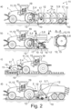
- Fig. 1 shows several agricultural attachments 3 that can be used in the proposed method, specifically a baler 7, a fertilizer spreader 8 and a plough 9. In Fig. 2 these are shown in action.
- the embodiment shown in the figures and preferred in this respect relates to a method for determining coupling form-independent working heights 10 of several agricultural attachments 3 by means of a sensor arrangement 11, wherein the sensor arrangement 11 has at least one sensor 12 for recording measurement data and a control arrangement 13, wherein the attachments 3 can be coupled to an agricultural work machine 1 via at least one device interface 2 by different coupling forms and wherein the attachments 3 are temporarily coupled to the agricultural work machine 1 by the different coupling forms.
- the measurement data are transmitted from the sensor 12 to the control arrangement 13.
- the different coupling forms can allow different use of the same Device interface 2, the connection of different attachments 3 and/or different device interfaces 2.
- at least two different coupling forms are used in the proposed method. These can of course be used at different times. For example, a plough 9 can be attached to a rear power lift at the start of the season, while a mower can be attached to the front power lift during the harvest.
- the term "coupling form-independent working height” means a working height 10 that is not calculated relative to the device interface 2. Specifically, for example, an incomplete coupling or a change in the coupling should not have any influence on the determined working height 10, provided that this does not interfere with the measurement.
- the sensor arrangement 11 can be independent as such or at least partially integrated into the agricultural work machine 1.
- the control arrangement 13 of the sensor arrangement 11 can be, for example, a control arrangement 13 of the agricultural work machine 1.
- it can also consist of distributed computing units. It can, for example, have a control unit of the agricultural work machine 1 and a cloud control unit.
- an absolute working height 10 is preferably measured as a working height 10 independent of the coupling form.
- the term "absolute” does not necessarily mean a highly precise measurement, but rather a general measurement relative to the ground. In principle, it is conceivable that the measurement is carried out relative to a component whose height relative to the ground is known, but preferably the absolute working height 10 is measured directly relative to the ground. It can also be a working depth if the attachment 3 reaches into the ground.
- the working height 10 relates to a component of the agricultural attachment 3 that is used for field cultivation. This field cultivation can, however, also be sowing or the like.
- the transmission of the measurement data from the sensor 12 to the control arrangement 13 can in principle take place in any manner.
- the sensor 12 The data is not actively sent, it can also be read out.
- the transmission takes place regularly and/or continuously.
- control arrangement 13 determines the coupling form-independent working heights 10 of the differently coupled attachments 3 in the coupled state using the same sensor 12 and that the control arrangement 13 displays the determined coupling form-independent working heights 10 by means of the agricultural work machine 1 and/or uses them to control and/or regulate the agricultural work machine 1 and/or the agricultural attachment 3, wherein a coupling form-independent working height is a working height that is not calculated relative to the device interface.
- the display of the coupling form-independent working height 10 preferably takes place on a terminal 15 of the agricultural work machine 1, but can also take place on a smartphone, a tablet, a laptop, a smartwatch or the like.
- this sensor 12 is essential. As will be explained later, this sensor 12 can be located on the agricultural work machine 1. Another preferred option is to reuse the sensor 12 on different attachments 3. This will also be explained in more detail.
- the figures show both options and a total of several sensors 12 in each case. However, just one of the sensors 12 shown can also be present.
- control arrangement 13 it is possible for the control arrangement 13 to document the coupling form-independent working heights 10, at least partially, in particular to incorporate them into a documentation of field processing.
- control arrangement 13 determines the working height 10 completely independently of the coupling form and preferably completely independently of the device interface 2. Additionally or alternatively, it can be provided that the control arrangement 13 determines the working heights 10 primarily, preferably exclusively, via the sensor 12.
- the working height 10 is determined primarily via the sensor 12, other sensors 12 can be used to support it.
- a stereo camera on the other hand, would count as a sensor 12 here. Determining the working height 10 from a variety of parameters, including a tire pressure sensor, for example, does not count as a determination primarily via the tire pressure sensor.
- the sensor 12 is either attached to the agricultural work machine 1 or to the agricultural attachment 3. In principle, however, there is nothing to prevent sensors 12 from being attached to the agricultural work machine 1 and the agricultural attachment 3.
- the senor 12 is attached to the agricultural work machine 1, preferably that the sensor 12 is an optical sensor 12, in particular a camera.
- the camera is preferably a stereo camera.
- the sensor 12 on the agricultural work machine 1 measures the working height 10 on the attachment 3 without contact. It can be provided that no machine parameters of the agricultural work machine 1 are taken into account. In particular, however, it can be provided that a positioning of the sensor 12 is taken into account when determining the working height 10. Information about the type and type of the agricultural attachment 3 can also be taken into account.
- the senor 12 can be reversibly mounted on the attachments 3 and that the sensor 12 is used to determine the working height 10 of several attachments 3 and is mounted on the attachment 3 for this purpose.
- the sensor arrangement 11 can have at least one sensor holder 16, wherein the sensor 12 is reversibly mounted by means of the at least one sensor holder 16 at a mounting position 17 on different attachments 3, wherein the sensor 12 in the mounted state records measurement data relating to a working height 10 of the attachment 3 and transmits it to the control arrangement 13 and wherein the control arrangement 13 determines the working height 10 of the respective attachment 3 from a mounting position-specific calibration data set.
- the sensor 12 is mounted using the sensor holder 16 at the mounting position 17 in such a way that the mounting is non-destructive and reversible. In particular, it is not carried out as part of the manufacture of the attachment 3, but is preferably possible on site in the field using simple tools or without any tools at all.
- the calibration data set can in principle be stored in any memory, be newly created or be otherwise available to the control arrangement 13.
- the sensor arrangement 11 can be independent of the attachment 3. Alternatively, it can be provided that the sensor 12 does not communicate with the attachment 3. However, it can also be provided that the sensor 12 is integrated into the electronics of the attachment 3 or communicates with it. Even with attachments 3 with electronics, however, it can be provided that the sensor 12 does not communicate directly with the attachment 3. It is preferred that the sensor arrangement 11 can be used with attachments 3 with and without electronics. Overall, it can even be provided that the determination of the working height 10, apart from the calibration itself, is completely independent of the agricultural attachment 3.
- the mounting position-specific calibration data sets include a reference height and/or an orientation of the sensor 12 in the mounted state at the respective mounting position 17 and/or a localization of the mounting position 17 relative to the attachment 3.
- the reference height can come from a calibration routine to be explained later and relates to a height of the mounting position 17 of the sensor 12 in a reference state, preferably at a known working height 10.
- the orientation of the sensor 12 can, for example, be a tilting of the sensor 12. This can take into account that the sensor 12 may not measure the shortest distance to the ground.
- the location of the mounting position 17 relative to the attachment 3 can be selected from a group of predetermined mounting positions 17 or determined in some other way.
- Fig. 1 for example, represents two mounting positions 17 on a plow 9.
- Fig. 2 shows several possible mounting positions 17 on different attachments 3.
- the localization of the mounting position 17 of one or more sensors 12 may be necessary.
- the mounting position-specific calibration data sets are stored in a memory of the control arrangement 13.
- This memory is here and preferably a local memory of the agricultural work machine 1. In principle, however, a cloud storage or the like can also be considered.
- Calibration data sets relating to mounting positions 17 on at least two, preferably at least three, different types of attachments 3 can be stored in the memory.
- the sensor holder 16 remains on the attachment 3.
- this has clear advantages in the context of the calibration routine to be explained below, but on the other hand it also enables the sensor holder 16 to be mounted in a stable and more complex manner, while mounting the sensor 12 on the sensor holder 16 itself is preferably relatively simple. This also enables the same mounting position 17 to be reused when the sensor 12 is attached again. Accordingly, the mounting position-specific calibration data set can also be assigned to the sensor holder 16 at the corresponding mounting position 17. In order to map this assignment, it can be provided that the sensor holder 16 has an identification feature 18.
- the identification feature 18 can be transmitted from the sensor holder 16 to the control arrangement 13. In some embodiments, however, this sensor holder 16 does not have its own electronics. In particular, it can therefore also be provided that the sensor 12, in particular in the mounted state, reads the identification feature 18 and transmits it to the control arrangement 13.
- the sensor holder 16 preferably has an NFC tag.
- the sensor 12 can then have an NFC reader, by means of which the sensor 12 reads the identification feature 18 of the sensor holder 16 and transmits it to the control arrangement 13.
- the user 19 can enter the identification feature 18 via an input device, in particular a smartphone, or read it with the smartphone.
- the input device then communicates with the control arrangement 13 or is part of the control arrangement 13.
- the identification feature 18 can thus also be a QR code, which the user 19 reads out, for example, in a dedicated app. All of these options allow for quick installation of the sensor 12, which leads directly to the usability of the sensor 12 for determining the working height 10.
- a user 19 selects the mounting position-specific calibration data set on an input unit, preferably an input unit of an agricultural work machine 1 that communicates with the control arrangement 13, or that the control arrangement 13 automatically selects the mounting position-specific calibration data set on the basis of the identification feature 18.
- control arrangement 13 carries out a calibration routine in which the control arrangement 13 generates a calibration data set specific to the mounting position and preferably stores it in the memory.
- This calibration routine is explained in more detail below. It is preferably provided that in the calibration routine the control arrangement 13 stores a reference height and/or an alignment of the sensor 12 in the mounted state at the respective mounting position 17 and/or a localization of the mounting position 17 relative to the attachment 3 in the mounting position-specific calibration data set.
- the calibration routine is carried out here and preferably on level ground.
- the control arrangement 13 can inform the user 19 that he should park the agricultural work machine 1 and/or the attachment 3 on level ground. should and/or assume that this has happened.
- the attachment 3 assumes a reference height.
- the reference height can be set, for example, at a working height 10 of zero when the ploughshares 14 are parked on the ground.
- the lowest adjustable height and a usual working height 10 are too far apart to calibrate the sensor 12 and still remain within the specification of the sensor 12 during use. Therefore, it can also be provided that the user 19 has to enter the reference height or determine it in some other way.
- the control arrangement 13 uses the sensor 12 to measure the distance between the sensor 12 and the ground in the calibration routine and stores this as a reference height.
- the installation position 17, which can be specified by the control arrangement 13 does not have to be precisely maintained by the user 19, particularly in the height direction, since it is reduced from the reference height when determining the working height 10. In other directions, too, high precision is usually not important due to the tolerances prevailing in agriculture.
- the attachment 3 has its own setting options for the working height 10, it can be provided that the settings present during the calibration routine are also saved in the mounting position-specific calibration data set and changes to these settings can lead to a warning to the user 19 or, if necessary, be taken into account when determining the working height 10 by means of a model of the attachment 3.
- control arrangement 13 guides a user 19 through the calibration routine by means of an output unit in a natural language dialog, preferably that the control arrangement 13 specifies an installation position 17 to the user 19 or the user 19 transmits the installation position 17, preferably by voice input, to the control arrangement 13. Additionally or alternatively, it can be provided that the control arrangement 13 specifies a setting of a working height 10 of the attachment 3 to the user 19 or the user 19 transmits the setting of a working height 10, preferably by voice input, to the control arrangement 13, and/or that the control arrangement 13 specifies to the user 19 that the agricultural work machine 1 and/or the attachment 3 should be parked on level ground.
- the dialogue can be carried out using a voice output device and/or voice input device of the agricultural work machine 1 and/or a smartphone.
- a terminal 15 of the agricultural work machine 1 and/or the smartphone can also be used without voice input and/or output.
- the agricultural work machine 1 and/or the attachment 3 is on level ground during the calibration routine, that the user 19 mounts the sensor holder 16 at a mounting position 17 on an agricultural attachment 3 and connects the sensor 12 to the sensor holder 16 and that the control arrangement 13 carries out a calibration routine in which the control arrangement 13 determines a reference height and generates a mounting position-specific calibration data set and preferably stores it in the memory.
- the output unit may be the terminal 15 or the smartphone and/or have the voice output device.
- the senor 12 can be mounted on the sensor holder 16 in a form-fitting and/or force-fitting manner, preferably that the sensor 12 can be mounted on the sensor holder 16 by means of a quick-release device and/or by means of one or more screws and/or magnetically and/or can be clipped into the sensor holder 16.
- the sensor 12 can preferably be mounted on the sensor holder 16 using commercially available tools or without any tools at all.
- the sensor holder 16 has a battery and/or an electrical connection unit, in particular a cable or an antenna, for connection to the control arrangement 13 and/or for transmitting energy from an agricultural work machine 1 to the sensor 12, preferably that the electrical connection unit has a bus connection, in particular an ISOBUS or CAN bus connection.
- the sensor 12 in particular can be supplied with energy.
- the sensor holder 16 can be used to transmit the data from the sensor 12 to the control arrangement 13. This is particularly interesting if the control arrangement 13 is part of the agricultural work machine 1 or the connection to the control arrangement 13 runs via the agricultural work machine 1. If the sensor holder 16 has a cable that can be connected to a bus of the agricultural work machine 1, if necessary, and the sensor holder 16 remains on the agricultural attachment 3, the wiring only has to be done once. This consistently further develops the "plug and play" concept of the sensor arrangement 11.
- the battery can of course alternatively be a rechargeable battery.
- the sensor 12 can also have its own battery or rechargeable battery.
- the sensor holder 16 does not have any electronics, whereby the NFC tag does not count as electronics. If the attachment 3 has its own power supply, which may be fed by the agricultural work machine 1, the sensor 12 can also be connected to this, in particular via the sensor holder 16.
- the senor 12 is a distance sensor, in particular a contactless one, preferably that the distance sensor functions on the basis of electromagnetic waves or acoustic waves or mechanical scanning. Furthermore, it is preferably the case that the distance sensor is a radar sensor or a lidar sensor or an optical sensor or an ultrasonic sensor, or that the sensor 12 is a sensor 12, in particular a force sensor or displacement sensor, on a component that touches the ground, in particular a sensing bracket, a sliding skid or a support roller.
- the sensor arrangement 11 has at least two sensors 12 with different functional principles, each of which can be reversibly mounted on the sensor holder 16. Because the sensors 12 can be used in a modular manner, several different sensors 12 can also be present, which are selected accordingly depending on the attachment 3 and/or the agricultural activity that is to be carried out. These are then preferably each compatible with the same sensor holder 16.
- the attachments 3 comprise different types of attachments 3, for which the control arrangement 13 determines a working height 10 independent of the coupling form.
- the different types of attachments 3 preferably comprise at least one type of soil tillage device, more preferably at least two types of soil tillage devices.
- the types of soil tillage devices preferably comprise a plough 9 and/or a cultivator and/or a harrow.
- the different types of attachments 3 preferably comprise a seed drill and/or a fertilizer spreader 8, in particular a seed coulter, and/or a mower and/or a pickup and/or an attachment 3 with a pickup, in particular a baler 7 or a loading wagon.
- the attachments 3 are separate vehicles with at least one of their own axle and their own wheels.
- the attachment 3 can be designed without an axle or wheels and can be carried by the tractor or another attachment 3. In this regard, reference is made to the device interfaces 2 already mentioned.
- control arrangement 13 determines several coupling form-independent working heights 10 for at least one of the attachments 3, in particular several of the differently coupled attachments 3, preferably that the sensor arrangement 11 has several sensors 12, that the control arrangement 13 uses one sensor 12 each to determine one of the coupling form-independent working heights 10 on the same attachment 3, further preferably that the control arrangement 13 uses the several sensors 12 each to determine coupling form-independent working heights 10 of the differently coupled attachments 3.
- control arrangement 13 additionally determines the working height 10 from an attachment-specific calibration data set and the attachment-specific calibration data set includes a kinematics of the respective attachment 3. Additionally or alternatively, it can be the case that the control arrangement 13 additionally determines the working height 10 from a coupling data set and the Coupling data set comprises machine parameters of a device interface 2 between the agricultural work machine 1 and the respective attachment 3, preferably that the coupling data set comprises machine parameters of a three-point power lift 4.
- the number of sensors 12 required to determine several working heights 10 can be reduced, for example via an axis transformation using the kinematics of the attachment 3 or via known machine parameters of the device interface 2.
- the determination of a single working height 10 can also be verified or made more precise in this way if necessary. In a preferred embodiment, however, at least one working height 10 can be determined without taking the machine parameters of the device interface 2 into account.
- the attachment-specific calibration data set can be contained in the mounting position-specific calibration data set or vice versa.
- the coupling data set can be attachment-specific, but does not have to be.
- it can include lengths of hydraulic cylinders of the device interface 2.
- machine parameters are understood to mean all settings, associated sensor measurements and the like.
- the machine parameters at least partially relate to machine parameters that have a direct influence on the working height 10 that is to be determined.
- control arrangement 13 may regulate a working height 10 of the attachment 3 taking into account the determined coupling form-independent working height 10 of the attachment 3, preferably for the control arrangement 13 to regulate the working height 10 of the respective attachment 3 to a predetermined target working height 20 and for this purpose the coupling form-independent working height 10 is returned and offset against the target working height 20, further preferably for a control variable of the control to be a machine parameter of the attachment 3 and/or the device interface 2.
- the proposed sensor arrangement 11 enables a less complex and efficient control of the working height 10 of the attachment 3.
- the target working height 20 can be specified by the user 19, calculated dynamically, come from a farm management information system and the like.
- the target working height 20 takes into account local conditions of the field and/or working heights 10 of past work tasks, which were also carried out in particular by determining a working height 10 with the proposed sensor arrangement 11.
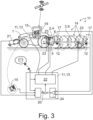
- the control is shown schematically in Fig. 3
- the target working height 20 can be derived from a user input, another system or a front-end sensor 21. Together with feedback of the measured working heights 10, it is fed into a control block 22, from which target values of control variables for actuators 23 are derived.
- the machine parameters of the attachment 3 can, for example, be settings of hydraulic cylinders that adjust a height of the attachment 3. Furthermore, the machine parameters can be settings of the three-point power lift 4, in particular settings of the lower link 5 and/or the upper link 6. It is understood that the machine parameters serving as control variables have an influence on the working height 10 to be controlled.
- the control arrangement 13 regulates at least two working heights 10 of the attachment 3, preferably, the control arrangement 13 regulates a deviation of the working heights 10 at at least two positions of the attachment 3 and/or a transverse inclination of the attachment 3 and/or a longitudinal inclination of the attachment 3, further preferably, the control arrangement 13 minimizes the deviation of the working heights 10 and/or the transverse inclination and/or the longitudinal inclination or regulates it to a predetermined value.
- the kinematics of the attachment 3 are preferably taken into account. It can also be provided to determine the kinematics from the reaction of the attachment 3 to various changes in the control variables. For this purpose, a test drive can be provided to adjust the attachment 3.
- control arrangement 13 varies at least one control variable for regulating the working height 10, that the at least one control variable is a machine parameter of the agricultural working machine 1 and/or the attachment 3, preferably that the device interface 2 to which an attachment 3 is at least temporarily coupled is a three-point power lift 4, further Preferably, a control variable of the control is a machine parameter of the three-point linkage 4.
- control variables are, for example, the air pressure of the tires of the agricultural work machine 1 and general machine parameters of the agricultural work machine 1 that can influence the height of the device interface 2. This also includes, for example, axle loads. However, not all of these parameters can always be easily adjusted.
- Input parameters such as position control and/or traction control and/or mixed control and/or slip control of the agricultural working machine 1 and its device interface 2 can also serve as control variables. This option is particularly interesting because it can be used to build on existing controls.
- one of the attachments 3 is a plough 9, that a control variable of the control is a machine parameter, in particular a pressure of a hydraulic system, of the plough 9, and/or that one of the attachments 3 is a cultivator or a harrow, that a control variable of the control is a machine parameter, of the cultivator or the harrow, preferably that the machine parameter is a roller or a support wheel, in particular a height of the roller or the support wheel, of the cultivator or the harrow.
- the determined coupling form-independent working height 10 relates to a position on the attachment 3 which, in the direction of travel of the agricultural work machine 1, lies in front of a field processing position of the attachment 3, preferably that the control arrangement 13 regulates at least one working height 10 at the field processing position in advance, in particular in real time.
- the working height 10 can be adjusted in real time to the local conditions.
- a filter 24 is provided which, depending on the application, can be a low-pass filter, for example.
- ploughing for example, a quick reaction to potholes and the like will be rather negative or not possible at all, so that these can be filtered out of the measurement.
- a reaction to this can also be provided.
- This application also shows that the working height 10 can basically be measured at various positions of the agricultural attachment 3, depending on the application. This measurability is another advantage of the modular sensor technology.
- the target working height 20 of the control varies during field cultivation, preferably that the target working height 20 is location-dependent and/or is specified by the user 19 and/or is determined by the control arrangement 13 on the basis of measurement data from a soil sensor.
- the proposed solution makes it possible to adjust the working height 10 as required at various positions in the field during field cultivation. Accordingly, field cultivation planning can be provided in particular, which already specifies different target working heights 20 for the field. These can be implemented using a GPS system, for example.
- a sensor arrangement 11 in particular for use in a method according to the proposal, for determining coupling-form-independent working heights 10 of several agricultural attachments 3, wherein the sensor arrangement 11 has at least one sensor 12 for recording measurement data and a control arrangement 13, wherein the attachments 3 can be coupled to an agricultural work machine 1 via at least one device interface 2 by means of different coupling forms.
- control arrangement 13 is set up to determine the coupling form-independent working heights 10 of the differently coupled attachments 3 in the coupled state using the same sensor 12 and that the Control arrangement 13 is set up to display the determined coupling form-independent working heights 10 by means of the agricultural work machine 1 and/or to use them for controlling and/or regulating the agricultural work machine 1, wherein a coupling form-independent working height is a working height that is not calculated relative to the device interface.
- an agricultural working machine 1 with a sensor arrangement 11 according to the proposal is also proposed.
Landscapes
- Life Sciences & Earth Sciences (AREA)
- Engineering & Computer Science (AREA)
- Mechanical Engineering (AREA)
- Soil Sciences (AREA)
- Environmental Sciences (AREA)
- Zoology (AREA)
- Lifting Devices For Agricultural Implements (AREA)
Claims (15)
- Procédé de détermination de hauteurs de travail (10) indépendantes de la forme de l'attelage de plusieurs outils agricoles attelés (3) à l'aide d'un dispositif à capteur (11), le dispositif à capteur (11) présentant au moins un capteur (12), destiné à recueillir des données de mesure, et un dispositif de commande (13), les outils attelés (3) pouvant être accouplés à une machine de travail agricole (1) par l'intermédiaire d'au moins une interface d'outil (2), via des formes d'attelage différentes, les outils attelés (3) étant accouplés temporairement à la machine agricole (1) par les différentes formes d'attelage,
caractérisé en ce que
le dispositif de commande (13) détermine, à l'état accouplé, les hauteurs de travail (10) indépendantes de la forme de l'attelage des outils attelés (3) accouplés de manière différente, en utilisant le même capteur (12), et en ce que le dispositif de commande (13) visualise, au moyen de la machine agricole (1), les hauteurs de travail (10) indépendantes de la forme de l'attelage déterminées et/ou les utilise pour la commande et/ou le réglage de la machine agricole (1) et/ou de l'outil agricole attelé (3), une hauteur de travail (10) indépendante de la forme de l'attelage étant une hauteur de travail (10) qui n'est pas calculée par rapport à l'interface d'outil (2). - Procédé selon la revendication 1, caractérisé en ce que le dispositif de commande (13) détermine la hauteur de travail (10) de manière totalement indépendante de la forme de l'attelage et, de préférence, de manière totalement indépendante de l'interface d'outil (2), et/ou en ce que le dispositif de commande (13) détermine les hauteurs de travail (10) de façon primaire, de préférence exclusivement, par l'intermédiaire du capteur (12).
- Procédé selon la revendication 1 ou 2, caractérisé en ce que le capteur (12) est monté sur la machine agricole (1), de préférence, en ce que le capteur (12) est un capteur optique (12), notamment une caméra.
- Procédé selon la revendication 1 ou 2, caractérisé en ce que le capteur (12) peut être monté de façon réversible sur les outils attelés (3), en ce que le capteur (12) est utilisé pour déterminer la hauteur de travail (10) de plusieurs outils attelés (3) et est à cet effet monté respectivement sur l'outil attelé (3).
- Procédé selon une revendication 4, caractérisé en ce que le capteur (12) est un capteur de distance, notamment sans contact, de préférence en ce que le capteur de distance fonctionne sur la base d'ondes électromagnétiques ou d'ondes acoustiques ou de palpage mécanique, en outre, de préférence, en ce que le capteur de distance est un capteur radar ou un capteur Lidar ou un capteur optique ou un capteur à ultrasons, ou en ce que le capteur (12) est un capteur (12), notamment un capteur de force ou un capteur de déplacement, sur un composant en contact avec le sol, notamment un étrier palpeur, un patin frottant ou un rouleau de support.
- Procédé selon une des revendications précédentes, caractérisé en ce que les outils attelés (3) comprennent différents types d'outils attelés (3) pour lesquels le dispositif de commande (13) détermine respectivement une hauteur de travail (10) indépendante de la forme de l'attelage, les différents types d'outils attelés (3) comprenant de préférence au moins un type d'outil de travail du sol, en outre de préférence au moins deux types d'outils de travail du sol, les types d'outils de travail du sol comprenant de préférence une charrue (9) et/ou un décompacteur et/ou une herse, et/ou les différents types d'outils attelés (3) comprenant un semoir et/ou un distributeur d'engrais chimique (8), notamment un soc semeur, et/ou un mécanisme de coupe et/ou un ramasseur et/ou un outil attelé (3) doté d'un ramasseur, notamment une presse à balles (7) ou une remorque autochargeuse.
- Procédé selon une des revendications précédentes, caractérisé en ce que le dispositif de commande (13) détermine pour au moins un des outils attelés (3), notamment plusieurs des outils attelés (3) à accouplements différents, plusieurs hauteurs de travail (10) indépendantes de la forme de l'attelage, de préférence en ce que le dispositif à capteur (11) présente plusieurs capteurs (12), en ce que le dispositif à capteur (11) utilise respectivement un capteur (12) pour déterminer l'une des hauteurs de travail (10) indépendantes de la forme de l'attelage, sur le même outil attelé (3), en outre de préférence en ce que le dispositif de commande (13) utilise la pluralité de capteurs (12) respectivement pour déterminer des hauteurs de travail (10) indépendantes de la forme de l'attelage des outils attelés (3) accouplés de manière différente.
- Procédé selon une des revendications précédentes, caractérisé en ce que le dispositif de commande (13) règle une hauteur de travail (10) de l'outil attelé (3) en tenant compte de la hauteur de travail (10) indépendante de la forme de l'attelage déterminée de l'outil attelé (3), de préférence en ce que le dispositif de commande (13) règle la hauteur de travail (10) de l'outil attelé (3) respectif à une hauteur de travail de consigne (20) prédéfinie et qu'à cet effet la hauteur de travail (10) indépendante de la forme de l'attelage est renvoyée et compensée avec la hauteur de travail de consigne (20), en outre de préférence en ce qu'une grandeur réglante du réglage est un paramètre machine de l'outil attelé (3) et/ou de l'interface d'outil (2).
- Procédé selon les revendications 7 et 8, caractérisé en ce que le dispositif de commande (13) règle au moins deux hauteurs de travail (10) de l'outil attelé (3), de préférence en ce que le dispositif de commande (13) règle un écart des hauteurs de travail (10) dans au moins deux positions de l'outil attelé (3) et/ou une inclinaison transversale de l'outil attelé (3) et/ou une inclinaison longitudinale de l'outil attelé (3), en outre de préférence en ce que le dispositif de commande (13) règle à un minimum ou à une valeur prédéfinie l'écart des hauteurs de travail (10) et/ou l'inclinaison transversale et/ou l'inclinaison longitudinale.
- Procédé selon une des revendications 8 ou 9, caractérisé en ce que, en vue du réglage de la hauteur de travail (10), le dispositif de commande (13) fait varier au moins une grandeur réglante, en ce que la grandeur réglante, au nombre d'au moins une, est un paramètre machine de la machine agricole (1) et/ou de l'outil attelé (3), de préférence en ce que l'interface d'outil (2), à laquelle un outil attelé (3) est accouplé au moins temporairement, est un relevage à trois points (4), en outre de préférence en ce qu'une grandeur réglante du réglage est un paramètre machine du relevage à trois points (4).
- Procédé selon une des revendications précédentes, caractérisé en ce que l'un des outils attelés (3) est une charrue (9), en ce qu'une grandeur réglante du réglage est un paramètre machine, notamment une pression d'une hydraulique, de la charrue (9), et/ou en ce que l'un des outils attelés (3) est un décompacteur ou une herse, en ce qu'une grandeur réglante du réglage est un paramètre machine du décompacteur ou de la herse, de préférence en ce que le paramètre machine est un rouleau ou une roue de support, notamment une hauteur du rouleau ou de la roue de support, du décompacteur ou de la herse.
- Procédé selon une des revendications précédentes, caractérisé en ce que la hauteur de travail (10) indépendante de la forme de l'attelage déterminée concerne une position sur l'outil attelé (3) qui se situe avant une position d'un travail de champ de l'outil attelé (3), vu dans le sens du déplacement de la machine agricole (1), de préférence en ce que le dispositif de commande (13) règle de manière prédictive, notamment en temps réel, au moins une hauteur de travail (10) dans la position du travail du champ.
- Procédé selon une des revendications 8 à 12, caractérisé en ce que la hauteur de travail de consigne (20) du réglage varie pendant le travail du champ, de préférence en ce que la hauteur de travail de consigne (20) est fonction du lieu et/ou est prédéfinie par l'utilisateur (19) et/ou est déterminée par le dispositif de commande (13) sur la base de données de mesure d'un capteur de sol.
- Dispositif à capteur, destiné notamment à être utilisé dans un procédé selon une des revendications précédentes, aux fins de déterminer des hauteurs de travail (10) indépendantes de la forme de l'attelage, le dispositif à capteur (11) présentant au moins un capteur (12), destiné à recueillir des données de mesure, et un dispositif de commande (13), les outils attelés (3) pouvant être accouplés à une machine de travail agricole (1) par l'intermédiaire d'au moins une interface d'outil (2), via des formes d'attelage différentes,
caractérisé en ce que
le dispositif de commande (13) est conçu pour déterminer, à l'état accouplé, les hauteurs de travail (10) indépendantes de la forme de l'attelage des outils attelés (3), accouplés de manière différente, en utilisant le même capteur (12), et en ce que le dispositif de commande (13) est conçu pour visualiser, au moyen de la machine agricole (1), les hauteurs de travail (10) indépendantes de la forme de l'attelage déterminées et/ou les utiliser pour la commande et/ou le réglage de la machine agricole (1), une hauteur de travail (10) indépendante de la forme de l'attelage étant une hauteur de travail (10) qui n'est pas calculée par rapport à l'interface d'outil (2). - Machine de travail agricole dotée d'un dispositif à capteur (11) selon la revendication 14.
Applications Claiming Priority (1)
| Application Number | Priority Date | Filing Date | Title |
|---|---|---|---|
| DE102021120758.4A DE102021120758A1 (de) | 2021-08-10 | 2021-08-10 | Verfahren zur Ermittlung von kopplungsformunabhängigen Arbeitshöhen mehrerer landwirtschaftlicher Anbaugeräte |
Publications (2)
| Publication Number | Publication Date |
|---|---|
| EP4133922A1 EP4133922A1 (fr) | 2023-02-15 |
| EP4133922B1 true EP4133922B1 (fr) | 2025-02-26 |
Family
ID=81326277
Family Applications (1)
| Application Number | Title | Priority Date | Filing Date |
|---|---|---|---|
| EP22168289.1A Active EP4133922B1 (fr) | 2021-08-10 | 2022-04-14 | Méthode de détermination des hauteurs de travail indépendantes de la forme d'attelage de plusieurs outils agricoles |
Country Status (3)
| Country | Link |
|---|---|
| US (1) | US20230047045A1 (fr) |
| EP (1) | EP4133922B1 (fr) |
| DE (1) | DE102021120758A1 (fr) |
Families Citing this family (4)
| Publication number | Priority date | Publication date | Assignee | Title |
|---|---|---|---|---|
| DE102019122114A1 (de) * | 2019-08-16 | 2021-02-18 | Claas Tractor Sas | Landwirtschaftliche Zugmaschine |
| US11750791B2 (en) * | 2021-10-19 | 2023-09-05 | Mineral Earth Sciences Llc | Automatically determining extrinsic parameters of modular edge computing devices |
| US20250135813A1 (en) * | 2023-11-01 | 2025-05-01 | Kubota Corporation | Working machine |
| DE102024104853A1 (de) * | 2024-02-21 | 2025-08-21 | Maschinenfabrik Bernard Krone GmbH & Co. KG | Arbeitszug mit einem schlepper und einem anbaugerät |
Family Cites Families (11)
| Publication number | Priority date | Publication date | Assignee | Title |
|---|---|---|---|---|
| DE10214648A1 (de) * | 2002-04-02 | 2003-10-16 | Claas Selbstfahr Erntemasch | Messeinrichtung an einer landwirtschaftlichen Maschine |
| US20080257569A1 (en) * | 2007-04-17 | 2008-10-23 | Chris Foster | Electronic draft control for trailed implements |
| US20100287898A1 (en) * | 2009-05-18 | 2010-11-18 | Cnh America, Llc | Ground speed implement height control adjustment rate on agricultural vehicles |
| SE535699C2 (sv) * | 2011-01-26 | 2012-11-13 | Vaederstad Verken Ab | Lantbruksredskap samt metod för bearbetning av jord |
| US8241098B1 (en) * | 2011-05-12 | 2012-08-14 | Latimer Leslie B | Adjustable conveyor assembly for a combine |
| US11041284B2 (en) * | 2017-02-20 | 2021-06-22 | Cnh Industrial America Llc | System and method for coupling an implement to a work vehicle |
| DE102017116593A1 (de) * | 2017-07-24 | 2019-01-24 | Amazonen-Werke H. Dreyer Gmbh & Co. Kg | Verfahren zum Unterstützen eines Maschinenbedieners beim Einstellen einer landwirtschaftlichen Bodenbearbeitungsmaschine |
| AT520903B1 (de) | 2018-02-14 | 2019-11-15 | Geoprospectors Gmbh | Vorrichtung und Verfahren zur Bodenbearbeitung |
| DE102018203245A1 (de) * | 2018-03-05 | 2019-09-05 | Robert Bosch Gmbh | Verfahren zum Kalibrieren und Betreiben eines elektronisch-hydraulischen Hubwerks einer Landmaschine |
| EP3729939A1 (fr) * | 2019-04-25 | 2020-10-28 | CNH Industrial Sweden AB | Procédé de réglage de la profondeur de travail d'un outil agricole et charrue |
| DE102019125280A1 (de) * | 2019-09-19 | 2021-03-25 | Carl Geringhoff Gmbh & Co. Kg | Schneidwerk mit Sensoren zur Höhenregelung |
-
2021
- 2021-08-10 DE DE102021120758.4A patent/DE102021120758A1/de active Pending
-
2022
- 2022-04-14 EP EP22168289.1A patent/EP4133922B1/fr active Active
- 2022-08-04 US US17/880,913 patent/US20230047045A1/en active Pending
Also Published As
| Publication number | Publication date |
|---|---|
| US20230047045A1 (en) | 2023-02-16 |
| EP4133922A1 (fr) | 2023-02-15 |
| DE102021120758A1 (de) | 2023-02-16 |
Similar Documents
| Publication | Publication Date | Title |
|---|---|---|
| EP4133922A1 (fr) | Procédé de détermination des hauteurs de travail indépendantes du type d'accouplement d'une pluralité d'accessoires agricoles | |
| EP3251485B1 (fr) | Machine de travail agricole automotrice avec un système de surveillance et/ou de contrôle de l'état de marche et procédé | |
| EP3305052B1 (fr) | Dispositif de commande, tracteur avec un dispositif de commande et procédé pour un dispositif de commande | |
| DE102019114872A1 (de) | System und Verfahren zur Simulation und/oder Konfiguration eines mittels einer landwirtschaftlichen Arbeitsmaschine durchzuführenden Arbeitsprozesses und landwirtschaftliche Arbeitsmaschine | |
| EP3858644B1 (fr) | Tracteur | |
| DE102016121523A1 (de) | Verfahren zum prädikativen Erzeugen von Daten zur Steuerung eines Fahrweges und eines Betriebsablaufes für landwirtschaftliche Fahrzeuge und Maschinen | |
| EP3709786B1 (fr) | Procédé permettant de faire fonctionner un système composé d'un véhicule de travail agricole et d'au moins un équipement de travail agencé au niveau dudit véhicule | |
| EP4133921B1 (fr) | Procédé de collecte de données de mesure agricoles dans une machine de travail agricole | |
| DE102012201333A1 (de) | Landwirtschaftliche Maschine mit einem System zur selbsttätigen Einstellung eines Bearbeitungsparameters und zugehöriges Verfahren | |
| EP4133920A2 (fr) | Procédé de mesure d'une hauteur absolue de travail d'une pluralité d'accessoires agricoles | |
| DE102017217391A1 (de) | Landwirtschaftliches Arbeitsfahrzeug | |
| EP3756433B1 (fr) | Système de commande d'un outil de travail raccordé à un véhicule | |
| DE102018124705A1 (de) | Nachrüstkit zum Anbau an ein landwirtschaftliches Gerät | |
| EP3537863A1 (fr) | Procédé de génération de données de manière prédictive destiné à la commande d'une voie et d'une séquence de fonctionnement pour véhicules et machines agricoles | |
| DE102019114869A1 (de) | Steuersystem und Verfahren zum Betreiben einer landwirtschaftlichen Arbeitsmaschine sowie landwirtschaftliche Arbeitsmaschine | |
| DE102019112958A1 (de) | Verfahren zur landwirtschaftlichen Bodenbearbeitung, Werkzeugsystem, Generatormodul sowie deren Verwendung | |
| WO2016192973A1 (fr) | Dispositif de commande pour un tracteur, tracteur présentant un dispositif de commande et procédé pour un dispositif de commande | |
| EP4133923B1 (fr) | Procédé d'optimisation préalable des processus agricoles pour attelages agricoles | |
| DE102019111317A1 (de) | Autonome landwirtschaftliche Arbeitsmaschine und Verfahren zu deren Betrieb | |
| EP4133926A1 (fr) | Procédé de planification d'un processus optimisé de traitement du sol | |
| EP3895531A1 (fr) | Système d'épandage agricole, procédé d'ajustement d'une quantité d'application, ainsi que machine d'épandage agricole | |
| EP4133925B1 (fr) | Procédé de fonctionnement d'une combinaison véhicule-outil agricole | |
| EP3533307A1 (fr) | Procédé de commande d'un bras supérieur hydraulique d'un attelage trois points | |
| EP1300061A1 (fr) | Procédé et dispositif pour la détermination des paramètres pour les travaux de champs | |
| EP4133927B1 (fr) | Procédé d'optimisation du réglage des paramètres machine d'un attelage agricole |
Legal Events
| Date | Code | Title | Description |
|---|---|---|---|
| PUAI | Public reference made under article 153(3) epc to a published international application that has entered the european phase |
Free format text: ORIGINAL CODE: 0009012 |
|
| STAA | Information on the status of an ep patent application or granted ep patent |
Free format text: STATUS: THE APPLICATION HAS BEEN PUBLISHED |
|
| AK | Designated contracting states |
Kind code of ref document: A1 Designated state(s): AL AT BE BG CH CY CZ DE DK EE ES FI FR GB GR HR HU IE IS IT LI LT LU LV MC MK MT NL NO PL PT RO RS SE SI SK SM TR |
|
| P01 | Opt-out of the competence of the unified patent court (upc) registered |
Effective date: 20230516 |
|
| STAA | Information on the status of an ep patent application or granted ep patent |
Free format text: STATUS: REQUEST FOR EXAMINATION WAS MADE |
|
| 17P | Request for examination filed |
Effective date: 20230816 |
|
| RBV | Designated contracting states (corrected) |
Designated state(s): AL AT BE BG CH CY CZ DE DK EE ES FI FR GB GR HR HU IE IS IT LI LT LU LV MC MK MT NL NO PL PT RO RS SE SI SK SM TR |
|
| GRAP | Despatch of communication of intention to grant a patent |
Free format text: ORIGINAL CODE: EPIDOSNIGR1 |
|
| STAA | Information on the status of an ep patent application or granted ep patent |
Free format text: STATUS: GRANT OF PATENT IS INTENDED |
|
| RIC1 | Information provided on ipc code assigned before grant |
Ipc: A01B 79/02 20060101ALI20240925BHEP Ipc: A01B 69/00 20060101ALI20240925BHEP Ipc: A01B 63/111 20060101AFI20240925BHEP |
|
| INTG | Intention to grant announced |
Effective date: 20241011 |
|
| GRAS | Grant fee paid |
Free format text: ORIGINAL CODE: EPIDOSNIGR3 |
|
| GRAA | (expected) grant |
Free format text: ORIGINAL CODE: 0009210 |
|
| STAA | Information on the status of an ep patent application or granted ep patent |
Free format text: STATUS: THE PATENT HAS BEEN GRANTED |
|
| AK | Designated contracting states |
Kind code of ref document: B1 Designated state(s): AL AT BE BG CH CY CZ DE DK EE ES FI FR GB GR HR HU IE IS IT LI LT LU LV MC MK MT NL NO PL PT RO RS SE SI SK SM TR |
|
| REG | Reference to a national code |
Ref country code: GB Ref legal event code: FG4D Free format text: NOT ENGLISH |
|
| REG | Reference to a national code |
Ref country code: CH Ref legal event code: EP |
|
| REG | Reference to a national code |
Ref country code: DE Ref legal event code: R096 Ref document number: 502022002990 Country of ref document: DE |
|
| REG | Reference to a national code |
Ref country code: IE Ref legal event code: FG4D Free format text: LANGUAGE OF EP DOCUMENT: GERMAN |
|
| REG | Reference to a national code |
Ref country code: NL Ref legal event code: MP Effective date: 20250226 |
|
| PG25 | Lapsed in a contracting state [announced via postgrant information from national office to epo] |
Ref country code: RS Free format text: LAPSE BECAUSE OF FAILURE TO SUBMIT A TRANSLATION OF THE DESCRIPTION OR TO PAY THE FEE WITHIN THE PRESCRIBED TIME-LIMIT Effective date: 20250526 |
|
| PG25 | Lapsed in a contracting state [announced via postgrant information from national office to epo] |
Ref country code: FI Free format text: LAPSE BECAUSE OF FAILURE TO SUBMIT A TRANSLATION OF THE DESCRIPTION OR TO PAY THE FEE WITHIN THE PRESCRIBED TIME-LIMIT Effective date: 20250226 |
|
| PG25 | Lapsed in a contracting state [announced via postgrant information from national office to epo] |
Ref country code: PL Free format text: LAPSE BECAUSE OF FAILURE TO SUBMIT A TRANSLATION OF THE DESCRIPTION OR TO PAY THE FEE WITHIN THE PRESCRIBED TIME-LIMIT Effective date: 20250226 |
|
| PGFP | Annual fee paid to national office [announced via postgrant information from national office to epo] |
Ref country code: DE Payment date: 20250422 Year of fee payment: 4 |
|
| PG25 | Lapsed in a contracting state [announced via postgrant information from national office to epo] |
Ref country code: ES Free format text: LAPSE BECAUSE OF FAILURE TO SUBMIT A TRANSLATION OF THE DESCRIPTION OR TO PAY THE FEE WITHIN THE PRESCRIBED TIME-LIMIT Effective date: 20250226 |
|
| REG | Reference to a national code |
Ref country code: LT Ref legal event code: MG9D |
|
| PG25 | Lapsed in a contracting state [announced via postgrant information from national office to epo] |
Ref country code: NO Free format text: LAPSE BECAUSE OF FAILURE TO SUBMIT A TRANSLATION OF THE DESCRIPTION OR TO PAY THE FEE WITHIN THE PRESCRIBED TIME-LIMIT Effective date: 20250526 Ref country code: IS Free format text: LAPSE BECAUSE OF FAILURE TO SUBMIT A TRANSLATION OF THE DESCRIPTION OR TO PAY THE FEE WITHIN THE PRESCRIBED TIME-LIMIT Effective date: 20250626 |
|
| PG25 | Lapsed in a contracting state [announced via postgrant information from national office to epo] |
Ref country code: NL Free format text: LAPSE BECAUSE OF FAILURE TO SUBMIT A TRANSLATION OF THE DESCRIPTION OR TO PAY THE FEE WITHIN THE PRESCRIBED TIME-LIMIT Effective date: 20250226 |
|
| PG25 | Lapsed in a contracting state [announced via postgrant information from national office to epo] |
Ref country code: HR Free format text: LAPSE BECAUSE OF FAILURE TO SUBMIT A TRANSLATION OF THE DESCRIPTION OR TO PAY THE FEE WITHIN THE PRESCRIBED TIME-LIMIT Effective date: 20250226 |
|
| PG25 | Lapsed in a contracting state [announced via postgrant information from national office to epo] |
Ref country code: PT Free format text: LAPSE BECAUSE OF FAILURE TO SUBMIT A TRANSLATION OF THE DESCRIPTION OR TO PAY THE FEE WITHIN THE PRESCRIBED TIME-LIMIT Effective date: 20250626 Ref country code: LV Free format text: LAPSE BECAUSE OF FAILURE TO SUBMIT A TRANSLATION OF THE DESCRIPTION OR TO PAY THE FEE WITHIN THE PRESCRIBED TIME-LIMIT Effective date: 20250226 |
|
| PGFP | Annual fee paid to national office [announced via postgrant information from national office to epo] |
Ref country code: FR Payment date: 20250425 Year of fee payment: 4 |
|
| PG25 | Lapsed in a contracting state [announced via postgrant information from national office to epo] |
Ref country code: BG Free format text: LAPSE BECAUSE OF FAILURE TO SUBMIT A TRANSLATION OF THE DESCRIPTION OR TO PAY THE FEE WITHIN THE PRESCRIBED TIME-LIMIT Effective date: 20250226 Ref country code: GR Free format text: LAPSE BECAUSE OF FAILURE TO SUBMIT A TRANSLATION OF THE DESCRIPTION OR TO PAY THE FEE WITHIN THE PRESCRIBED TIME-LIMIT Effective date: 20250527 |
|
| PGFP | Annual fee paid to national office [announced via postgrant information from national office to epo] |
Ref country code: AT Payment date: 20250721 Year of fee payment: 4 |
|
| PG25 | Lapsed in a contracting state [announced via postgrant information from national office to epo] |
Ref country code: SE Free format text: LAPSE BECAUSE OF FAILURE TO SUBMIT A TRANSLATION OF THE DESCRIPTION OR TO PAY THE FEE WITHIN THE PRESCRIBED TIME-LIMIT Effective date: 20250226 |
|
| PG25 | Lapsed in a contracting state [announced via postgrant information from national office to epo] |
Ref country code: SM Free format text: LAPSE BECAUSE OF FAILURE TO SUBMIT A TRANSLATION OF THE DESCRIPTION OR TO PAY THE FEE WITHIN THE PRESCRIBED TIME-LIMIT Effective date: 20250226 |
|
| PG25 | Lapsed in a contracting state [announced via postgrant information from national office to epo] |
Ref country code: DK Free format text: LAPSE BECAUSE OF FAILURE TO SUBMIT A TRANSLATION OF THE DESCRIPTION OR TO PAY THE FEE WITHIN THE PRESCRIBED TIME-LIMIT Effective date: 20250226 |
|
| PG25 | Lapsed in a contracting state [announced via postgrant information from national office to epo] |
Ref country code: IT Free format text: LAPSE BECAUSE OF FAILURE TO SUBMIT A TRANSLATION OF THE DESCRIPTION OR TO PAY THE FEE WITHIN THE PRESCRIBED TIME-LIMIT Effective date: 20250226 |
|
| PG25 | Lapsed in a contracting state [announced via postgrant information from national office to epo] |
Ref country code: EE Free format text: LAPSE BECAUSE OF FAILURE TO SUBMIT A TRANSLATION OF THE DESCRIPTION OR TO PAY THE FEE WITHIN THE PRESCRIBED TIME-LIMIT Effective date: 20250226 Ref country code: CZ Free format text: LAPSE BECAUSE OF FAILURE TO SUBMIT A TRANSLATION OF THE DESCRIPTION OR TO PAY THE FEE WITHIN THE PRESCRIBED TIME-LIMIT Effective date: 20250226 |
|
| PG25 | Lapsed in a contracting state [announced via postgrant information from national office to epo] |
Ref country code: RO Free format text: LAPSE BECAUSE OF FAILURE TO SUBMIT A TRANSLATION OF THE DESCRIPTION OR TO PAY THE FEE WITHIN THE PRESCRIBED TIME-LIMIT Effective date: 20250226 |
|
| PG25 | Lapsed in a contracting state [announced via postgrant information from national office to epo] |
Ref country code: SK Free format text: LAPSE BECAUSE OF FAILURE TO SUBMIT A TRANSLATION OF THE DESCRIPTION OR TO PAY THE FEE WITHIN THE PRESCRIBED TIME-LIMIT Effective date: 20250226 |
|
| REG | Reference to a national code |
Ref country code: CH Ref legal event code: H13 Free format text: ST27 STATUS EVENT CODE: U-0-0-H10-H13 (AS PROVIDED BY THE NATIONAL OFFICE) Effective date: 20251125 |
|
| REG | Reference to a national code |
Ref country code: DE Ref legal event code: R097 Ref document number: 502022002990 Country of ref document: DE |
|
| PG25 | Lapsed in a contracting state [announced via postgrant information from national office to epo] |
Ref country code: LU Free format text: LAPSE BECAUSE OF NON-PAYMENT OF DUE FEES Effective date: 20250414 |
|
| PG25 | Lapsed in a contracting state [announced via postgrant information from national office to epo] |
Ref country code: MC Free format text: LAPSE BECAUSE OF FAILURE TO SUBMIT A TRANSLATION OF THE DESCRIPTION OR TO PAY THE FEE WITHIN THE PRESCRIBED TIME-LIMIT Effective date: 20250226 |
|
| REG | Reference to a national code |
Ref country code: BE Ref legal event code: MM Effective date: 20250430 |
|
| PLBE | No opposition filed within time limit |
Free format text: ORIGINAL CODE: 0009261 |
|
| STAA | Information on the status of an ep patent application or granted ep patent |
Free format text: STATUS: NO OPPOSITION FILED WITHIN TIME LIMIT |
|
| PG25 | Lapsed in a contracting state [announced via postgrant information from national office to epo] |
Ref country code: BE Free format text: LAPSE BECAUSE OF NON-PAYMENT OF DUE FEES Effective date: 20250430 |
|
| PG25 | Lapsed in a contracting state [announced via postgrant information from national office to epo] |
Ref country code: CH Free format text: LAPSE BECAUSE OF NON-PAYMENT OF DUE FEES Effective date: 20250430 |
|
| 26N | No opposition filed |
Effective date: 20251127 |
|
| PG25 | Lapsed in a contracting state [announced via postgrant information from national office to epo] |
Ref country code: IE Free format text: LAPSE BECAUSE OF NON-PAYMENT OF DUE FEES Effective date: 20250414 |