EP4133984B1 - Module de retrait du sac à poussière et aspirateur - Google Patents
Module de retrait du sac à poussière et aspirateur Download PDFInfo
- Publication number
- EP4133984B1 EP4133984B1 EP22187246.8A EP22187246A EP4133984B1 EP 4133984 B1 EP4133984 B1 EP 4133984B1 EP 22187246 A EP22187246 A EP 22187246A EP 4133984 B1 EP4133984 B1 EP 4133984B1
- Authority
- EP
- European Patent Office
- Prior art keywords
- dust bag
- removal module
- vacuum cleaner
- dust
- bag removal
- Prior art date
- Legal status (The legal status is an assumption and is not a legal conclusion. Google has not performed a legal analysis and makes no representation as to the accuracy of the status listed.)
- Active
Links
Images







Classifications
-
- A—HUMAN NECESSITIES
- A47—FURNITURE; DOMESTIC ARTICLES OR APPLIANCES; COFFEE MILLS; SPICE MILLS; SUCTION CLEANERS IN GENERAL
- A47L—DOMESTIC WASHING OR CLEANING; SUCTION CLEANERS IN GENERAL
- A47L9/00—Details or accessories of suction cleaners, e.g. mechanical means for controlling the suction or for effecting pulsating action; Storing devices specially adapted to suction cleaners or parts thereof; Carrying-vehicles specially adapted for suction cleaners
- A47L9/10—Filters; Dust separators; Dust removal; Automatic exchange of filters
- A47L9/14—Bags or the like; Rigid filtering receptacles; Attachment of, or closures for, bags or receptacles
- A47L9/1427—Means for mounting or attaching bags or filtering receptacles in suction cleaners; Adapters
- A47L9/1436—Connecting plates, e.g. collars, end closures
-
- A—HUMAN NECESSITIES
- A47—FURNITURE; DOMESTIC ARTICLES OR APPLIANCES; COFFEE MILLS; SPICE MILLS; SUCTION CLEANERS IN GENERAL
- A47L—DOMESTIC WASHING OR CLEANING; SUCTION CLEANERS IN GENERAL
- A47L9/00—Details or accessories of suction cleaners, e.g. mechanical means for controlling the suction or for effecting pulsating action; Storing devices specially adapted to suction cleaners or parts thereof; Carrying-vehicles specially adapted for suction cleaners
- A47L9/10—Filters; Dust separators; Dust removal; Automatic exchange of filters
- A47L9/14—Bags or the like; Rigid filtering receptacles; Attachment of, or closures for, bags or receptacles
-
- A—HUMAN NECESSITIES
- A47—FURNITURE; DOMESTIC ARTICLES OR APPLIANCES; COFFEE MILLS; SPICE MILLS; SUCTION CLEANERS IN GENERAL
- A47L—DOMESTIC WASHING OR CLEANING; SUCTION CLEANERS IN GENERAL
- A47L9/00—Details or accessories of suction cleaners, e.g. mechanical means for controlling the suction or for effecting pulsating action; Storing devices specially adapted to suction cleaners or parts thereof; Carrying-vehicles specially adapted for suction cleaners
- A47L9/10—Filters; Dust separators; Dust removal; Automatic exchange of filters
- A47L9/14—Bags or the like; Rigid filtering receptacles; Attachment of, or closures for, bags or receptacles
- A47L9/1427—Means for mounting or attaching bags or filtering receptacles in suction cleaners; Adapters
Definitions
- the invention relates to a dust bag removal module and a vacuum cleaner for cleaning and maintaining floor surfaces with a housing, a blower for generating a negative pressure for collecting dust by means of an air flow, wherein the blower is arranged in a blower chamber of the housing, and a dust chamber in the housing connected to the blower chamber for receiving a dust bag for cleaning the absorbed air of dust, wherein the dust chamber is accessible for changing the dust bag via a dust chamber opening that can be covered with a housing cover.
- the floor surface can be a textile floor covering such as a carpet or rug or a hard floor such as wooden parquet, laminate or PVC floor covering.
- a dust bag for such a vacuum cleaner today usually comprises a holding plate for fastening in a dust chamber of the vacuum cleaner, with an inlet opening being let into the holding plate for receiving a dust-laden air flow from the vacuum cleaner, with a filter bag made of an air-permeable material that is open to the inlet opening being arranged on the holding plate, with the material of the filter bag being designed to filter the dust out of the air flow as the air flow passes through.
- the inlet opening let into the holding plate is provided with a flap that closes the dust bag when it is removed from the dust chamber so that dust collected in the filter bag cannot escape again via the inlet opening.
- the inlet opening is usually provided with a seal that seals the dust bag from an inlet nozzle of the vacuum cleaner that dips into the inlet opening.
- the US 2005 098039 A1 discloses a dust bag removal module with a first coupling point for connection to a vacuum cleaner and a second coupling point for connection to a dust bag, wherein the dust bag removal module has a gripping surface and an ejection mechanism for separating the dust bag.
- the EN 10 2019 123150 A1 discloses a dust bag with a holding plate on which a pull tab is arranged.
- the DE 29 821 276 U1 discloses a dust bag with a holding plate to which a holding bracket is attached.
- the invention therefore addresses the problem of providing a solution that enables simpler, more sustainable and resource-saving operation of a vacuum cleaner.
- the amount of waste generated when changing the dust bag should be reduced and handling when changing the dust bag should be simplified.
- the dust bag removal module for manual arrangement in a vacuum cleaner and for manual removal from the vacuum cleaner, wherein the dust bag removal module has a first, multiply separable and connectable coupling interface for separation and connection to the vacuum cleaner and a second, multiply separable and connectable coupling interface for separation and connection to a dust bag, wherein the dust bag removal module has a gripping surface for manually grasping the dust bag removal module when removing and separating the first coupling interface from the vacuum cleaner and when arranging and connecting the first coupling interface to the vacuum cleaner, and wherein the dust bag removal module has a decoupling device for manually separating the connection to the dust bag at the second coupling interface, handling when changing the dust bag can be simplified and at the same time resources can be saved because the amount of waste can be reduced by changing the dust bag.
- the dust bag removal module simplifies the manual arrangement and removal of a dust bag in a vacuum cleaner by a user. For this purpose, the user can easily handle the dust bag removal module using the handle surface.
- the first, multiple separable and connectable coupling interface of the dust bag removal module enables the device to be disconnected from the vacuum cleaner when the dust bag is removed via the dust bag removal module.
- the connection of the dust bag removal module to the vacuum cleaner can also be established very easily via the first, multiple separable and connectable coupling interface when a new dust bag is inserted into the vacuum cleaner with the dust bag removal module.
- the dust bag removal module also has the second coupling interface for previously connecting the dust bag to the dust bag removal module.
- a decoupling device is provided on the dust bag removal module that enables the connection between the full dust bag and the Dust bag removal module on the second coupling interface. Thanks to the multiple detachable and connectable coupling interfaces of the dust bag removal module, it can be used multiple times when changing the dust bag and does not need to be replaced. It secures the dust bag sufficiently in the dust compartment of the vacuum cleaner so that a complex holding plate that is replaced with the dust bag is not necessary. This reduces the complexity of the dust bag and the waste generated when changing the dust bag, thus saving valuable resources in a simple way.
- the full dust bag can be very easily lifted out of the dust compartment using the handle on the dust bag removal module and an empty bag can be easily inserted into the dust compartment of the vacuum cleaner by the user using the handle on the dust bag removal module.
- the second coupling interface is designed to create a locking connection to a dust bag, wherein the decoupling device is designed to separate this locking connection to the dust bag.
- the locking connection can be used to create a particularly simple coupling interface between the dust bag and the dust bag removal module that can be separated or connected multiple times.
- the locking connection can also be easily separated by the user, so that the dust bag can be disengaged from the second coupling interface and disposed of separately from the dust bag removal module.
- the decoupling device for example over a trash can, the dust bag released from the second coupling interface can fall from the dust bag removal module into the trash can. The user can therefore handle the dust bag via the dust bag removal module and does not have to touch the dust bag directly for disposal.
- a bayonet lock or similar can also be provided on the second coupling interface.
- the dust bag removal module has an air duct for guiding an air flow from a coupled vacuum cleaner into a coupled dust bag.
- the dust-laden air flow of the coupled vacuum cleaner can be particularly easily the dust bag removal module into the coupled dust bag.
- the air duct advantageously forms a straight, tubular nozzle between the vacuum cleaner and the dust bag.
- At least one flap is arranged in the air duct, wherein the at least one flap is designed to be moved through the air duct into an open position by a differential pressure applied to the flap for the air flow of the coupled vacuum cleaner.
- the inlet opening of the dust bag can be closed via the flap in the dust bag removal module during handling of the dust bag removal module and storage of the switched off vacuum cleaner, so that no dirt escapes from the coupled dust bag via the air duct of the dust bag removal module.
- the vacuum cleaner applies a differential pressure to the flap when generating the air flow, the flap is opened so that the air flow can flow through the air duct of the dust bag removal module.
- a particularly advantageous embodiment of the invention therefore provides that the flap is designed to be moved by the differential pressure against the spring force of a spring into the open position, wherein the flap is further designed to be automatically moved back into a closed position to close the air duct by the spring force of the spring.
- the flap in the air duct is subjected to the spring force of a spring, which moves the flap from the open position back into the closed position as soon as the air flow of the vacuum cleaner stops, for example when the fan is switched off.
- the dust bag removal module has a seal for sealing against a coupled dust bag.
- the dust bag removal module By sealing the dust bag removal module against the dust bag, it is possible to prevent the air flow from the air duct of the dust bag removal module from flowing past the inlet opening of the dust bag. Since the seal is attached to the dust bag removal module, the dust bag can be replaced without replacing the seal, which reduces the waste generated for the change.
- the seal between the dust bag and the dust bag removal module can also be fixed to the inlet opening of the dust bag, so that the seal is replaced when the dust bag is changed. This can prevent the seal from failing over the service life of the vacuum cleaner. With the fixed arrangement of the seal on the dust bag removal module, the seal can also be simply replaced by by replacing the relatively simple dust bag removal module.
- a particularly advantageous embodiment is one in which the dust bag removal module has a seal for sealing against a coupled vacuum cleaner.
- the air flow can be prevented from flowing past the air duct of the dust bag removal module. Since the seal is attached to the dust bag removal module, the seal can be easily replaced by replacing the relatively simple dust bag removal module.
- the vacuum cleaner according to the invention which has already been described above and in more detail below, is characterized by a coupling receiving interface for receiving a dust bag removal module, which has already been described above and in more detail below, wherein a dust bag received in the dust chamber is coupled in the dust chamber via a dust bag removal module received at the coupling receiving interface.
- the coupling receiving interface very easily fixes the dust bag removal module in the dust chamber of the vacuum cleaner.
- the dust bag coupled to the dust bag removal module can thus be securely positioned in the dust chamber. This makes it easy to change the dust bag in this vacuum cleaner.
- the dust bag removal module can be securely positioned in the dust chamber to receive the dust bag coupled to the dust bag removal module.
- the vacuum cleaner has a blower for generating a negative pressure, through which a floor nozzle guided over a floor surface to be cleaned picks up dust and dirt from the floor surface.
- a blower for generating a negative pressure, through which a floor nozzle guided over a floor surface to be cleaned picks up dust and dirt from the floor surface.
- the user moves the floor nozzle back and forth in the direction of processing using pushing and pulling movements. This causes the floor nozzle to glide over the floor surface to be cleaned.
- the underside of the floor nozzle glides over the carpet, while with smooth floors the underside hovers over these floor surfaces at a distance, possibly by means of spacer bristles.
- the user can, for example, handle a handle of the vacuum cleaner connected to the suction pipe.
- the suction mouth of the floor nozzle is elongated and runs essentially transversely to the processing direction.
- elongated means that the preferably essentially rectangular suction mouth has a greater length transversely to the processing direction than its width in the processing direction.
- the suction mouth is preferably between 20 and 30 cm long across the processing direction.
- the vacuum cleaner can also be designed as a self-driving vacuum cleaner, in particular a robot vacuum cleaner, so that the processing direction of the floor nozzle corresponds to the direction of travel of the self-driving vacuum cleaner.
- An advantageous embodiment of the vacuum cleaner provides that the first coupling interface of a received dust bag removal module is coupled to the coupling receiving interface of the vacuum cleaner and that the second coupling interface of the received dust bag removal module is coupled to a dust bag received in the dust compartment.
- the dust bag can be placed very easily and safely in the dust compartment of the vacuum cleaner via the two coupling interfaces of the dust bag removal module.
- the coupling interfaces which can be separated and connected multiple times, enable the intermediate dust bag removal module to be reused when replacing the dust bag in the vacuum cleaner.
- the vacuum cleaner has a funnel-shaped threading slope on the housing cover, into which the dust bag removal module dips when the housing cover is closed.
- the funnel-shaped threading slope makes it very easy to ensure that the dust bag removal module is optimally positioned in the dust chamber of the vacuum cleaner after the housing cover is closed, thus optimally positioning the dust bag coupled to the dust bag removal module in the dust chamber.
- FIG. 1 A vacuum cleaner with a floor nozzle 19 is shown purely schematically with the reference number 2.
- the illustration according to Figure 1 shows a vacuum cleaner 2 according to the invention with a floor nozzle 19 connected to the vacuum cleaner 2.
- the vacuum cleaner 2 shown in the exemplary embodiment is a so-called canister vacuum cleaner.
- the floor nozzle 19 is connected here via its connection piece 20 to a suction pipe 21, which is preferably designed to be telescopic.
- the floor nozzle 19 in this exemplary embodiment shown has its own housing 22 which is independent of the vacuum cleaner housing 13.
- the telescopic suction pipe 21 extends into a handle 23 to which a suction hose 24 is connected, which is connected to the vacuum cleaner housing 13.
- a fan of the vacuum cleaner 2, which is integrated in the vacuum cleaner housing 13, is powered by an electrical connection cable 25 in order to generate a negative pressure.
- dirt and grime from the floor area B to be cleaned are picked up by an air stream via the suction mouth of the floor nozzle 19 and transported via the suction pipe 21 and the suction hose 24 into the housing 15 of the vacuum cleaner 2.
- a separation system which is designed as a dust bag 5.
- This separation system 5 is located in a dust chamber formed by the housing parts 13, 15 of the vacuum cleaner 2.
- This dust chamber 14 is accessible and open by a folding mechanism between the vacuum cleaner housing 13 and the housing cover 15 so that the dust bag 5 is visible and removable. To operate the vacuum cleaner 2, the dust chamber 14 is closed and a negative pressure is generated.
- the air stream generated by the negative pressure is freed of dirt and grime in the separation system 5 and guided out of the vacuum cleaner 2 via an exhaust air grille 26.
- a foot switch 27 (comment: this is actually the switch on the other side).
- This foot switch 27 includes switches that are large enough for users to operate them with their foot.
- the foot switch 27 usually also has a switch for operating the automatic winding mechanism for the connecting cable 25 integrated in the vacuum cleaner housing 13 (not shown).
- the handle 23 also has a secondary air regulator 28 with which the air flow at the floor nozzle can be interrupted if an object is accidentally sucked in with the floor nozzle.
- the floor nozzle 19 glides over the floor surface B to be cleaned. Especially with long-pile carpets, the underside of the floor nozzle 19 glides over the floor surface B, while with hard floors the underside is spaced apart, possibly by spacer bristles, over this floor surfaces B.
- the floor nozzle 19 also has support elements 29 in the form of wheels, which ensure a defined distance between the underside and the floor surfaces to be cleaned and easy handling when pushing the floor nozzle 19 back and forth.
- the Figure 2 shows a sectional view through the housing cover 15 of the vacuum cleaner 2 according to Figure 1 .
- a dust bag removal module 1 can also be seen and a holding plate 31 of a dust bag 5 coupled to the dust bag removal module 1 ( Fig.1 ).
- the holding plate 31 is permanently connected to the dust bag 5.
- the dust bag removal module 1 is used for the manual arrangement of dust bags 5 ( Fig.1 ) in a vacuum cleaner 2 ( Fig.1 ) and for manual removal of dust bags 5 ( Fig.1 ) from the vacuum cleaner 2 ( Fig.1 ).
- the dust bag removal module 1 shown has a first, multiple separable and connectable coupling interface 3 for separating and connecting to the vacuum cleaner 2 ( Fig.1 ).
- This nozzle-shaped coupling interface 3 of the dust bag removal module 1 is used to connect to the connection opening 32 for the suction hose 24 ( Fig.1 ) in the housing cover 15 of the vacuum cleaner 2.
- the vacuum cleaner 3 has a coupling receiving interface 17, which in the embodiment is arranged in the housing cover 15 of the vacuum cleaner 2.
- a dust chamber 14 ( Fig.1 ) dust bag 5 ( Fig.1 ) is thereby coupled via the dust bag removal module 1 received at the coupling receiving interface 17 in the dust chamber 14.
- the dust bag removal module 1 has a second, multiple separable and connectable coupling interface 4 for separating and connecting to the dust bag 5.
- the first coupling interface 3 of the accommodated dust bag removal module 1 is coupled to the coupling receiving interface 17 of the vacuum cleaner 2 and the second coupling interface 4 of the accommodated dust bag removal module 1 is coupled to the dust bag 5 accommodated in the dust chamber 14.
- the coupling receiving interface 17 has a funnel-shaped threading bevel 18 on the housing cover 15, into which the dust bag removal module 1 is inserted when the housing cover 15 is closed, as in Figure 2 to be seen.
- the dust bag removal module 1 has a gripping surface 6 for manually gripping the dust bag removal module 1 during removal and when separating the first coupling interface 3 from the vacuum cleaner 2 ( Fig.1 ).
- This gripping surface 6 also serves to manually grasp the dust bag removal module 1 by the user when arranging and connecting the first coupling interface 3 to the vacuum cleaner 2 ( Fig.1 ).
- the dust bag removal module 1 has a decoupling device 7 for manually disconnecting the connection to the dust bag 5 at the second coupling interface 4.
- This decoupling device 7 is designed as two opposing levers that can be manually operated by the user with a thumb and a finger to disconnect the connection between the dust bag 5 and the dust bag removal module 1 at the second coupling interface 4.
- the second coupling interface 4 can produce a latching connection 30 to the dust bag 5, wherein the simply designed holding plate 31 of the dust bag 5 is latched to an undercut 36 of the holding plate 31 at the second coupling interface 4.
- the decoupling device 7 is designed to disconnect this latching connection 30 to the dust bag 5.
- the levers rotate about the pivot point 35 and thus release the dust bag 5 at the second coupling interface 4.
- the locking connection 30 can advantageously be separated over a trash can, so that the dust bag 5, which is initially hanging over the trash can on the dust bag removal module 1, simply falls into the trash can. This means that the user does not have to touch the full dust bag 5 even when disposing of it.
- the grip surface 6 arranged on the dust bag removal module 1 serves this purpose, allowing easy handling of the dust bag removal module 1.
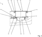
- the dust bag removal module 1 has a preferably tubular air guide 8 for guiding an air flow from the suction hose 24 of the coupled vacuum cleaner 2 into the coupled dust bag 5. While the Figure 2 shows a cross section through the dust bag removal module 1 arranged in the vacuum cleaner 2, is in Figure 3 a longitudinal section rotated by ninety degrees through the dust bag removal module 1 is shown.
- the Figure 3 thus shows a rotation around the central axis 33 of the dust bag removal module 2 by ninety degrees compared to the illustration in Figure 2 rotated sectional view.
- a two-part flap 9 is arranged in the air duct 8.
- the flap parts of the flap 9 are pivotally attached to the air duct 8.
- the two-part flap 9 closes the air duct 8 of the dust bag removal module 1. This ensures that the flap 9 in the closed position shown retains the dust in the filter bag of the full dust bag 5 when changing, i.e. when handling the dust bag removal module 1.
- FIG 4 is a similar sectional view as in Figure 3 shown, but here the two-part flap has been moved into an open position.
- the flap 9 is designed to be moved into an open position by a differential pressure applied to the flap 9 for the air flow of the coupled vacuum cleaner 2 through the air duct 8.
- the Figure 3 i.e. the closed position of the flap 9, which occurs when the vacuum cleaner 2, in particular the fan of the vacuum cleaner 2, is switched off and the air flow through the dust bag 5 is interrupted.
- the dust bag 5 is thus also closed during vacuuming breaks.
- the Figure 4 shows the opening position of the flap 8, which is reached when the vacuum cleaner 2 ( Fig.1 ), in particular the fan of the vacuum cleaner 2 ( Fig.1 ), are in operation and an air flow is generated through the coupled dust bag 5.
- the flap 9 is advantageously designed to be moved into the open position by the differential pressure against the spring force of a spring 10.
- the flap 9 is designed so that the spring force of the spring 10 automatically moves the flap 9 back into the Figure 3 shown locking position to close the air duct 8. This automatically closes the air duct 8 of the dust bag removal module 1 as soon as the fan of the coupled vacuum cleaner 2 ( Fig.1 ) is switched off and the air flow through the coupled dust bag 5 is interrupted. This can effectively prevent dust from escaping from a full dust bag 5 when changing the bag via the air duct 8 of the coupled dust bag removal module 1.
- the seal 11 is attached to the dust bag removal module 1, so the dust bag 5 can be replaced without replacing the seal 11, which reduces the waste generated during the replacement. Due to the fixed arrangement of the seal 11 on the dust bag removal module 1, the seal 11 can also be replaced simply by replacing the relatively simple dust bag removal module 1.
- This second seal 12 on the dust bag removal module 1 serves to seal against the coupled vacuum cleaner 2 ( Fig.1 ). By sealing the dust bag removal module 1 against the vacuum cleaner 2 ( Fig.1 ) can prevent the air flow from flowing past the air guide 8 of the dust bag removal module 1.
- the seal 12 on the dust bag removal module 1 can be easily replaced by replacing the relatively simple dust bag removal module 1.
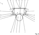
- FIG. 6 an embodiment of the dust bag removal module 1 is shown, which differs from the embodiment according to the Figures 2 to 5 differs in that the flap 9 is made in one piece.
- the circular flap 9 completely closes the tubular air duct 8 in the closed position.
- This one-piece flap 9 is only suspended on one side in the air duct 8, so that only one suspension and one spring 10 are required to move the flap 9 into the closed position.
- the execution according to Figure 7 differs from the versions according to the Figures 2 to 6 of the dust bag removal module 1 in particular in that the locking connection 30 engages the holding plate 31 of the dust bag 5 from the outside.
- the undercut 36 on the holding plate 31 is accessible from the outside and the levers of the decoupling device 7 rotate about the pivot point 35 when actuated and thus release the dust bag 5 at the second coupling interface 4.
- FIG 8 again an embodiment of the dust bag removal module 1 is shown, which in turn has a locking connection 30 which engages from the inside at the inlet opening 34 of the holding plate 31 of the dust bag 5 in the undercut 36 formed here.
- the levers of the decoupling device 7 When the levers of the decoupling device 7 are actuated, they rotate about the pivot point 35 and thus release the holding plate 31 of the dust bag 5 at the second coupling interface 4 of the dust bag removal module 1.
- FIG 9 a variant of the dust bag removal module 1 is shown which does not require a snap-in connection.
- the dust bag removal module 1 is simply inserted into the inlet opening 34 for coupling with the holding plate 31 of the dust bag 5 at the second coupling interface 4.
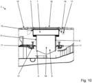
- the design of the dust bag removal module 1 according to Figure 10 differs from the execution according to Figure 9 in particular by the fact that instead of a two-part flap, a one-part flap 9 is provided in the air duct 8.
- FIG 11 again an example of the dust bag removal module 1 is shown, which has a locking connection 30 which engages from the outside on the holding plate 31 of the dust bag 5 in the undercut 36 formed here.
- the levers of the decoupling device 7 When the levers of the decoupling device 7 are actuated, they rotate about the pivot point 35 and thus release the holding plate 31 of the dust bag 5 at the second coupling interface 4 of the dust bag removal module 1.
- the circular, open flap 9 in the air duct 8 of the dust bag removal module 1 can also be seen.
- the holding plate 31 of the dust bag 5 at the inlet opening 34 no longer needs to be constructed as elaborately as is the case today. It is sufficient to have a border around the inlet opening 34 that forms a sufficiently large undercut 36 so that the dust bag 5 can be coupled to the dust bag removal module 1 at the second coupling interface 4.
- the invention described makes it possible to manufacture the entire dust bag 5 including the simple holding plate 31 from a single material.
- a PP-based nonwoven fabric for the filter bag with a simple holding plate 31 is also conceivable, also made of PP.
- a paper dust bag with a simple holding plate 31 made of cardboard is also possible.
Landscapes
- Engineering & Computer Science (AREA)
- Mechanical Engineering (AREA)
- Filters For Electric Vacuum Cleaners (AREA)
Claims (7)
- Module de retrait de sac à poussière (1) destiné à la disposition manuelle dans un aspirateur (2) et au retrait manuel hors de l'aspirateur (2), dans lequel le module de retrait de sac à poussière (1) présente une première interface d'accouplement (3) pouvant être séparée et reliée plusieurs fois pour la séparation de l'aspirateur (2) et la liaison avec celui-ci, et une seconde interface d'accouplement (4) pouvant être séparée et reliée plusieurs fois pour la séparation du sac à poussière (5) et la liaison avec celui-ci, dans lequel le module de retrait de sac à poussière (1) présente une surface de préhension (6) pour la prise manuelle du module de retrait de sac à poussière (1) lors du retrait et de la séparation de la première interface d'accouplement (3) de l'aspirateur (2) ainsi que lors de la disposition de la première interface d'accouplement (3) dans l'aspirateur (2) et de sa liaison avec celui-ci, et dans lequel le module de retrait de sac à poussière (1) présente un dispositif de désaccouplement (7) pour la séparation manuelle de la liaison avec le sac à poussière (5) au niveau de la seconde interface d'accouplement (4), dans lequel le module de retrait de sac à poussière (1) présente un guidage d'air (8) pour le guidage d'un flux d'air depuis un aspirateur (2) accouplé dans un sac à poussière (5) accouplé,
caractérisé en ce
qu'au moins un clapet (9) est disposé dans le guidage d'air (8), dans lequel l'au moins un clapet (9) est conçu pour être déplacé dans une position d'ouverture par une pression différentielle appliquée sur le clapet (9) par le guidage d'air (8) pour le flux d'air de l'aspirateur (2) accouplé. - Module de retrait de sac à poussière (1) selon la revendication 1, caractérisé en ce que la seconde interface d'accouplement (4) est conçue pour établir une liaison par encliquetage (30) avec un sac à poussière (5), dans lequel le dispositif de désaccouplement (7) est conçu pour séparer ladite liaison par encliquetage (30) avec le sac à poussière (5).
- Module de retrait de sac à poussière (1) selon la revendication 1, caractérisé en ce que le clapet (9) est conçu pour être déplacé dans la position d'ouverture par la pression différentielle à l'encontre de la force de ressort d'un ressort (10), dans lequel le clapet (9) est en outre conçu pour être à nouveau déplacé automatiquement dans une position de fermeture par la force de ressort du ressort (10) pour la fermeture du guidage d'air (8).
- Module de retrait de sac à poussière (1) selon l'une des revendications précédentes, caractérisé en ce que le module de retrait de sac à poussière (1) présente un joint d'étanchéité (11) permettant d'assurer l'étanchéité par rapport à un sac à poussière (5) accouplé.
- Module de retrait de sac à poussière (1) selon l'une des revendications précédentes, caractérisé en ce que le module de retrait de sac à poussière (1) présente un joint d'étanchéité (12) permettant d'assurer l'étanchéité par rapport à un aspirateur (2) accouplé.
- Aspirateur (2) permettant le nettoyage et l'entretien de surfaces de sol, comportant un boîtier (13), une soufflante permettant de générer une dépression pour la réception de la poussière au moyen d'un flux d'air, dans lequel la soufflante est disposée dans un espace pour soufflante du boîtier (13), et un espace pour poussière (14) relié à l'espace pour soufflante dans le boîtier (13) et permettant la réception d'un sac à poussière (5) permettant de nettoyer l'air réceptionné de la poussière, dans lequel l'espace pour poussière (14) est accessible pour le remplacement du sac à poussière (5) par l'intermédiaire d'une ouverture d'espace pour poussière (16) pouvant être recouverte par un couvercle de boîtier (15), dans lequel l'aspirateur (2) présente une interface de réception d'accouplement (17) pour la réception d'un module de retrait de sac à poussière (1) selon l'une des revendications précédentes 1 à 7, dans lequel un sac à poussière (5) réceptionné dans l'espace pour poussière (14) est accouplé dans l'espace pour poussière (14) par l'intermédiaire d'un module de retrait de sac à poussière (1) réceptionné sur l'interface de réception d'accouplement (17),
caractérisé en ce
que l'aspirateur (2) présente, sur le couvercle de boîtier (15), un biseau d'enfilage (18) en forme d'entonnoir dans lequel le module de retrait de sac à poussière (1) s'enfonce lors de la fermeture du couvercle de boîtier (15). - Aspirateur (1) selon la revendication 6, caractérisé en ce que la première interface d'accouplement (3) d'un module de retrait de sac à poussière (1) réceptionné est accouplée à l'interface de réception d'accouplement (17) de l'aspirateur (2) et en ce que la seconde interface d'accouplement (4) du module de retrait de sac à poussière (1) réceptionné est accouplée à un sac à poussière (5) réceptionné dans l'espace pour poussière (14).
Applications Claiming Priority (1)
| Application Number | Priority Date | Filing Date | Title |
|---|---|---|---|
| DE102021121091.7A DE102021121091A1 (de) | 2021-08-13 | 2021-08-13 | Staubbeutelentnahmemodul und Staubsauger |
Publications (2)
| Publication Number | Publication Date |
|---|---|
| EP4133984A1 EP4133984A1 (fr) | 2023-02-15 |
| EP4133984B1 true EP4133984B1 (fr) | 2024-06-26 |
Family
ID=82748693
Family Applications (1)
| Application Number | Title | Priority Date | Filing Date |
|---|---|---|---|
| EP22187246.8A Active EP4133984B1 (fr) | 2021-08-13 | 2022-07-27 | Module de retrait du sac à poussière et aspirateur |
Country Status (2)
| Country | Link |
|---|---|
| EP (1) | EP4133984B1 (fr) |
| DE (1) | DE102021121091A1 (fr) |
Family Cites Families (3)
| Publication number | Priority date | Publication date | Assignee | Title |
|---|---|---|---|---|
| DE29821276U1 (de) * | 1998-11-27 | 1999-03-11 | Aichner Filter GmbH, 92345 Dietfurt | Halteplatte eines Staubsauger-Filterbeutels |
| US7468083B2 (en) * | 2003-11-07 | 2008-12-23 | Panasonic Corporation Of North America | Vacuum cleaner equipped with bag mount and separate bag caddy |
| CN111067419B (zh) * | 2018-10-19 | 2022-12-20 | 德国福维克控股公司 | 滤尘袋 |
-
2021
- 2021-08-13 DE DE102021121091.7A patent/DE102021121091A1/de not_active Withdrawn
-
2022
- 2022-07-27 EP EP22187246.8A patent/EP4133984B1/fr active Active
Also Published As
| Publication number | Publication date |
|---|---|
| EP4133984A1 (fr) | 2023-02-15 |
| DE102021121091A1 (de) | 2023-02-16 |
Similar Documents
| Publication | Publication Date | Title |
|---|---|---|
| EP2866631B1 (fr) | Combinaison d'un mini-aspirateur et d'un boîtier d'aspirateur ainsi que mini-aspirateur et boîtier d'aspirateur | |
| EP2866633B1 (fr) | Association d'un aspirateur à main et un manche pour accueillir l'aspirateur à main | |
| DE202011050051U1 (de) | Staubbehälter und Staubsammler mit demselben | |
| DE10316083A1 (de) | Kantenreinigungssystem für Vakuumreiniger | |
| DE112009002152T5 (de) | Beutelankoppelanordnung für einen Staubsauger | |
| DE20321328U1 (de) | Staubsauger mit Filterschublade | |
| EP2866632B1 (fr) | Combinaison composée d'un mini-aspirateur et d'un bâti d'aspirateur-balai, ainsi que mini-aspirateur et bâti d'aspirateur-balai | |
| DE102019131614A1 (de) | Staubsauger, Staubbeutel und Reinigungssystem | |
| EP4133984B1 (fr) | Module de retrait du sac à poussière et aspirateur | |
| EP3692879B1 (fr) | Aspirateur cyclonique guidé à la main | |
| EP4070709B1 (fr) | Unité de dépoussiérage pour robot aspirateur et aspirateur robot | |
| EP4410169A1 (fr) | Unité de séparation dotée d'un élément de couplage destiné au couplage d'un élément d'actionnement | |
| DE69105299T2 (de) | Staubsauger. | |
| EP4133983B1 (fr) | Sac à poussière | |
| EP4154782B1 (fr) | Aspirateur et sac à poussière | |
| DE102020120368A1 (de) | Staubsauger | |
| EP3692884A1 (fr) | Récipient de matière aspirée et aspirateur cyclonique guidé à la main | |
| EP3692880B1 (fr) | Aspirateur cyclonique guidé à la main | |
| EP4467057A1 (fr) | Dispositif destiné à être utilisé comme accessoire d'un appareil de nettoyage de sol | |
| DE102023100690A1 (de) | Reinigungsstation und Reinigungssystem | |
| DE102023119446A1 (de) | Set, umfassend Staubsauger und Absaugstation | |
| DE102020117189A1 (de) | Bodendüse für Staubsauger und Staubsauger | |
| DE102021100072A1 (de) | Staubsauger | |
| DE102017102960A1 (de) | Staubsauger | |
| DE102018116687A1 (de) | Staubsauger |
Legal Events
| Date | Code | Title | Description |
|---|---|---|---|
| PUAI | Public reference made under article 153(3) epc to a published international application that has entered the european phase |
Free format text: ORIGINAL CODE: 0009012 |
|
| STAA | Information on the status of an ep patent application or granted ep patent |
Free format text: STATUS: THE APPLICATION HAS BEEN PUBLISHED |
|
| AK | Designated contracting states |
Kind code of ref document: A1 Designated state(s): AL AT BE BG CH CY CZ DE DK EE ES FI FR GB GR HR HU IE IS IT LI LT LU LV MC MK MT NL NO PL PT RO RS SE SI SK SM TR |
|
| STAA | Information on the status of an ep patent application or granted ep patent |
Free format text: STATUS: REQUEST FOR EXAMINATION WAS MADE |
|
| 17P | Request for examination filed |
Effective date: 20230816 |
|
| RBV | Designated contracting states (corrected) |
Designated state(s): AL AT BE BG CH CY CZ DE DK EE ES FI FR GB GR HR HU IE IS IT LI LT LU LV MC MK MT NL NO PL PT RO RS SE SI SK SM TR |
|
| GRAP | Despatch of communication of intention to grant a patent |
Free format text: ORIGINAL CODE: EPIDOSNIGR1 |
|
| STAA | Information on the status of an ep patent application or granted ep patent |
Free format text: STATUS: GRANT OF PATENT IS INTENDED |
|
| INTG | Intention to grant announced |
Effective date: 20240220 |
|
| GRAS | Grant fee paid |
Free format text: ORIGINAL CODE: EPIDOSNIGR3 |
|
| GRAA | (expected) grant |
Free format text: ORIGINAL CODE: 0009210 |
|
| STAA | Information on the status of an ep patent application or granted ep patent |
Free format text: STATUS: THE PATENT HAS BEEN GRANTED |
|
| REG | Reference to a national code |
Ref country code: DE Ref legal event code: R084 Ref document number: 502022001114 Country of ref document: DE |
|
| AK | Designated contracting states |
Kind code of ref document: B1 Designated state(s): AL AT BE BG CH CY CZ DE DK EE ES FI FR GB GR HR HU IE IS IT LI LT LU LV MC MK MT NL NO PL PT RO RS SE SI SK SM TR |
|
| REG | Reference to a national code |
Ref country code: GB Ref legal event code: FG4D Free format text: NOT ENGLISH |
|
| REG | Reference to a national code |
Ref country code: CH Ref legal event code: EP |
|
| REG | Reference to a national code |
Ref country code: DE Ref legal event code: R096 Ref document number: 502022001114 Country of ref document: DE |
|
| REG | Reference to a national code |
Ref country code: GB Ref legal event code: 746 Effective date: 20240724 |
|
| PG25 | Lapsed in a contracting state [announced via postgrant information from national office to epo] |
Ref country code: BG Free format text: LAPSE BECAUSE OF FAILURE TO SUBMIT A TRANSLATION OF THE DESCRIPTION OR TO PAY THE FEE WITHIN THE PRESCRIBED TIME-LIMIT Effective date: 20240626 |
|
| PG25 | Lapsed in a contracting state [announced via postgrant information from national office to epo] |
Ref country code: FI Free format text: LAPSE BECAUSE OF FAILURE TO SUBMIT A TRANSLATION OF THE DESCRIPTION OR TO PAY THE FEE WITHIN THE PRESCRIBED TIME-LIMIT Effective date: 20240626 Ref country code: HR Free format text: LAPSE BECAUSE OF FAILURE TO SUBMIT A TRANSLATION OF THE DESCRIPTION OR TO PAY THE FEE WITHIN THE PRESCRIBED TIME-LIMIT Effective date: 20240626 |
|
| REG | Reference to a national code |
Ref country code: LT Ref legal event code: MG9D |
|
| PG25 | Lapsed in a contracting state [announced via postgrant information from national office to epo] |
Ref country code: GR Free format text: LAPSE BECAUSE OF FAILURE TO SUBMIT A TRANSLATION OF THE DESCRIPTION OR TO PAY THE FEE WITHIN THE PRESCRIBED TIME-LIMIT Effective date: 20240927 |
|
| PG25 | Lapsed in a contracting state [announced via postgrant information from national office to epo] |
Ref country code: LV Free format text: LAPSE BECAUSE OF FAILURE TO SUBMIT A TRANSLATION OF THE DESCRIPTION OR TO PAY THE FEE WITHIN THE PRESCRIBED TIME-LIMIT Effective date: 20240626 |
|
| REG | Reference to a national code |
Ref country code: NL Ref legal event code: MP Effective date: 20240626 |
|
| PG25 | Lapsed in a contracting state [announced via postgrant information from national office to epo] |
Ref country code: NO Free format text: LAPSE BECAUSE OF FAILURE TO SUBMIT A TRANSLATION OF THE DESCRIPTION OR TO PAY THE FEE WITHIN THE PRESCRIBED TIME-LIMIT Effective date: 20240926 Ref country code: LV Free format text: LAPSE BECAUSE OF FAILURE TO SUBMIT A TRANSLATION OF THE DESCRIPTION OR TO PAY THE FEE WITHIN THE PRESCRIBED TIME-LIMIT Effective date: 20240626 Ref country code: HR Free format text: LAPSE BECAUSE OF FAILURE TO SUBMIT A TRANSLATION OF THE DESCRIPTION OR TO PAY THE FEE WITHIN THE PRESCRIBED TIME-LIMIT Effective date: 20240626 Ref country code: GR Free format text: LAPSE BECAUSE OF FAILURE TO SUBMIT A TRANSLATION OF THE DESCRIPTION OR TO PAY THE FEE WITHIN THE PRESCRIBED TIME-LIMIT Effective date: 20240927 Ref country code: FI Free format text: LAPSE BECAUSE OF FAILURE TO SUBMIT A TRANSLATION OF THE DESCRIPTION OR TO PAY THE FEE WITHIN THE PRESCRIBED TIME-LIMIT Effective date: 20240626 Ref country code: BG Free format text: LAPSE BECAUSE OF FAILURE TO SUBMIT A TRANSLATION OF THE DESCRIPTION OR TO PAY THE FEE WITHIN THE PRESCRIBED TIME-LIMIT Effective date: 20240626 Ref country code: RS Free format text: LAPSE BECAUSE OF FAILURE TO SUBMIT A TRANSLATION OF THE DESCRIPTION OR TO PAY THE FEE WITHIN THE PRESCRIBED TIME-LIMIT Effective date: 20240926 |
|
| PG25 | Lapsed in a contracting state [announced via postgrant information from national office to epo] |
Ref country code: NL Free format text: LAPSE BECAUSE OF FAILURE TO SUBMIT A TRANSLATION OF THE DESCRIPTION OR TO PAY THE FEE WITHIN THE PRESCRIBED TIME-LIMIT Effective date: 20240626 |
|
| PG25 | Lapsed in a contracting state [announced via postgrant information from national office to epo] |
Ref country code: NL Free format text: LAPSE BECAUSE OF FAILURE TO SUBMIT A TRANSLATION OF THE DESCRIPTION OR TO PAY THE FEE WITHIN THE PRESCRIBED TIME-LIMIT Effective date: 20240626 |
|
| PG25 | Lapsed in a contracting state [announced via postgrant information from national office to epo] |
Ref country code: PT Free format text: LAPSE BECAUSE OF FAILURE TO SUBMIT A TRANSLATION OF THE DESCRIPTION OR TO PAY THE FEE WITHIN THE PRESCRIBED TIME-LIMIT Effective date: 20241028 |
|
| PG25 | Lapsed in a contracting state [announced via postgrant information from national office to epo] |
Ref country code: PT Free format text: LAPSE BECAUSE OF FAILURE TO SUBMIT A TRANSLATION OF THE DESCRIPTION OR TO PAY THE FEE WITHIN THE PRESCRIBED TIME-LIMIT Effective date: 20241028 |
|
| PG25 | Lapsed in a contracting state [announced via postgrant information from national office to epo] |
Ref country code: PL Free format text: LAPSE BECAUSE OF FAILURE TO SUBMIT A TRANSLATION OF THE DESCRIPTION OR TO PAY THE FEE WITHIN THE PRESCRIBED TIME-LIMIT Effective date: 20240626 |
|
| PG25 | Lapsed in a contracting state [announced via postgrant information from national office to epo] |
Ref country code: EE Free format text: LAPSE BECAUSE OF FAILURE TO SUBMIT A TRANSLATION OF THE DESCRIPTION OR TO PAY THE FEE WITHIN THE PRESCRIBED TIME-LIMIT Effective date: 20240626 |
|
| PG25 | Lapsed in a contracting state [announced via postgrant information from national office to epo] |
Ref country code: IS Free format text: LAPSE BECAUSE OF FAILURE TO SUBMIT A TRANSLATION OF THE DESCRIPTION OR TO PAY THE FEE WITHIN THE PRESCRIBED TIME-LIMIT Effective date: 20241026 |
|
| PG25 | Lapsed in a contracting state [announced via postgrant information from national office to epo] |
Ref country code: CZ Free format text: LAPSE BECAUSE OF FAILURE TO SUBMIT A TRANSLATION OF THE DESCRIPTION OR TO PAY THE FEE WITHIN THE PRESCRIBED TIME-LIMIT Effective date: 20240626 |
|
| PG25 | Lapsed in a contracting state [announced via postgrant information from national office to epo] |
Ref country code: RO Free format text: LAPSE BECAUSE OF FAILURE TO SUBMIT A TRANSLATION OF THE DESCRIPTION OR TO PAY THE FEE WITHIN THE PRESCRIBED TIME-LIMIT Effective date: 20240626 Ref country code: SK Free format text: LAPSE BECAUSE OF FAILURE TO SUBMIT A TRANSLATION OF THE DESCRIPTION OR TO PAY THE FEE WITHIN THE PRESCRIBED TIME-LIMIT Effective date: 20240626 |
|
| PG25 | Lapsed in a contracting state [announced via postgrant information from national office to epo] |
Ref country code: SM Free format text: LAPSE BECAUSE OF FAILURE TO SUBMIT A TRANSLATION OF THE DESCRIPTION OR TO PAY THE FEE WITHIN THE PRESCRIBED TIME-LIMIT Effective date: 20240626 Ref country code: ES Free format text: LAPSE BECAUSE OF FAILURE TO SUBMIT A TRANSLATION OF THE DESCRIPTION OR TO PAY THE FEE WITHIN THE PRESCRIBED TIME-LIMIT Effective date: 20240626 |
|
| PG25 | Lapsed in a contracting state [announced via postgrant information from national office to epo] |
Ref country code: SM Free format text: LAPSE BECAUSE OF FAILURE TO SUBMIT A TRANSLATION OF THE DESCRIPTION OR TO PAY THE FEE WITHIN THE PRESCRIBED TIME-LIMIT Effective date: 20240626 Ref country code: SK Free format text: LAPSE BECAUSE OF FAILURE TO SUBMIT A TRANSLATION OF THE DESCRIPTION OR TO PAY THE FEE WITHIN THE PRESCRIBED TIME-LIMIT Effective date: 20240626 Ref country code: RO Free format text: LAPSE BECAUSE OF FAILURE TO SUBMIT A TRANSLATION OF THE DESCRIPTION OR TO PAY THE FEE WITHIN THE PRESCRIBED TIME-LIMIT Effective date: 20240626 Ref country code: PL Free format text: LAPSE BECAUSE OF FAILURE TO SUBMIT A TRANSLATION OF THE DESCRIPTION OR TO PAY THE FEE WITHIN THE PRESCRIBED TIME-LIMIT Effective date: 20240626 Ref country code: IS Free format text: LAPSE BECAUSE OF FAILURE TO SUBMIT A TRANSLATION OF THE DESCRIPTION OR TO PAY THE FEE WITHIN THE PRESCRIBED TIME-LIMIT Effective date: 20241026 Ref country code: ES Free format text: LAPSE BECAUSE OF FAILURE TO SUBMIT A TRANSLATION OF THE DESCRIPTION OR TO PAY THE FEE WITHIN THE PRESCRIBED TIME-LIMIT Effective date: 20240626 Ref country code: EE Free format text: LAPSE BECAUSE OF FAILURE TO SUBMIT A TRANSLATION OF THE DESCRIPTION OR TO PAY THE FEE WITHIN THE PRESCRIBED TIME-LIMIT Effective date: 20240626 Ref country code: CZ Free format text: LAPSE BECAUSE OF FAILURE TO SUBMIT A TRANSLATION OF THE DESCRIPTION OR TO PAY THE FEE WITHIN THE PRESCRIBED TIME-LIMIT Effective date: 20240626 |
|
| PG25 | Lapsed in a contracting state [announced via postgrant information from national office to epo] |
Ref country code: IT Free format text: LAPSE BECAUSE OF FAILURE TO SUBMIT A TRANSLATION OF THE DESCRIPTION OR TO PAY THE FEE WITHIN THE PRESCRIBED TIME-LIMIT Effective date: 20240626 |
|
| PG25 | Lapsed in a contracting state [announced via postgrant information from national office to epo] |
Ref country code: LU Free format text: LAPSE BECAUSE OF NON-PAYMENT OF DUE FEES Effective date: 20240727 |
|
| PG25 | Lapsed in a contracting state [announced via postgrant information from national office to epo] |
Ref country code: MC Free format text: LAPSE BECAUSE OF FAILURE TO SUBMIT A TRANSLATION OF THE DESCRIPTION OR TO PAY THE FEE WITHIN THE PRESCRIBED TIME-LIMIT Effective date: 20240626 |
|
| REG | Reference to a national code |
Ref country code: DE Ref legal event code: R097 Ref document number: 502022001114 Country of ref document: DE |
|
| PG25 | Lapsed in a contracting state [announced via postgrant information from national office to epo] |
Ref country code: MC Free format text: LAPSE BECAUSE OF FAILURE TO SUBMIT A TRANSLATION OF THE DESCRIPTION OR TO PAY THE FEE WITHIN THE PRESCRIBED TIME-LIMIT Effective date: 20240626 Ref country code: LU Free format text: LAPSE BECAUSE OF NON-PAYMENT OF DUE FEES Effective date: 20240727 |
|
| PG25 | Lapsed in a contracting state [announced via postgrant information from national office to epo] |
Ref country code: DK Free format text: LAPSE BECAUSE OF FAILURE TO SUBMIT A TRANSLATION OF THE DESCRIPTION OR TO PAY THE FEE WITHIN THE PRESCRIBED TIME-LIMIT Effective date: 20240626 |
|
| PG25 | Lapsed in a contracting state [announced via postgrant information from national office to epo] |
Ref country code: BE Free format text: LAPSE BECAUSE OF NON-PAYMENT OF DUE FEES Effective date: 20240731 |
|
| PLBE | No opposition filed within time limit |
Free format text: ORIGINAL CODE: 0009261 |
|
| STAA | Information on the status of an ep patent application or granted ep patent |
Free format text: STATUS: NO OPPOSITION FILED WITHIN TIME LIMIT |
|
| 26N | No opposition filed |
Effective date: 20250327 |
|
| REG | Reference to a national code |
Ref country code: BE Ref legal event code: MM Effective date: 20240731 |
|
| PG25 | Lapsed in a contracting state [announced via postgrant information from national office to epo] |
Ref country code: IE Free format text: LAPSE BECAUSE OF NON-PAYMENT OF DUE FEES Effective date: 20240727 |
|
| PG25 | Lapsed in a contracting state [announced via postgrant information from national office to epo] |
Ref country code: SE Free format text: LAPSE BECAUSE OF FAILURE TO SUBMIT A TRANSLATION OF THE DESCRIPTION OR TO PAY THE FEE WITHIN THE PRESCRIBED TIME-LIMIT Effective date: 20240626 |
|
| PGFP | Annual fee paid to national office [announced via postgrant information from national office to epo] |
Ref country code: DE Payment date: 20250731 Year of fee payment: 4 |
|
| PGFP | Annual fee paid to national office [announced via postgrant information from national office to epo] |
Ref country code: FR Payment date: 20250725 Year of fee payment: 4 Ref country code: AT Payment date: 20251020 Year of fee payment: 4 |
|
| PG25 | Lapsed in a contracting state [announced via postgrant information from national office to epo] |
Ref country code: CY Free format text: LAPSE BECAUSE OF FAILURE TO SUBMIT A TRANSLATION OF THE DESCRIPTION OR TO PAY THE FEE WITHIN THE PRESCRIBED TIME-LIMIT; INVALID AB INITIO Effective date: 20220727 |
|
| REG | Reference to a national code |
Ref country code: CH Ref legal event code: H13 Free format text: ST27 STATUS EVENT CODE: U-0-0-H10-H13 (AS PROVIDED BY THE NATIONAL OFFICE) Effective date: 20260224 |
|
| PG25 | Lapsed in a contracting state [announced via postgrant information from national office to epo] |
Ref country code: HU Free format text: LAPSE BECAUSE OF FAILURE TO SUBMIT A TRANSLATION OF THE DESCRIPTION OR TO PAY THE FEE WITHIN THE PRESCRIBED TIME-LIMIT; INVALID AB INITIO Effective date: 20220727 |
|
| PG25 | Lapsed in a contracting state [announced via postgrant information from national office to epo] |
Ref country code: CH Free format text: LAPSE BECAUSE OF NON-PAYMENT OF DUE FEES Effective date: 20250731 |