EP4134486B1 - Dispositif d'arrêt d'eau de type à coulissement suspendu et son application - Google Patents
Dispositif d'arrêt d'eau de type à coulissement suspendu et son application Download PDFInfo
- Publication number
- EP4134486B1 EP4134486B1 EP21935888.4A EP21935888A EP4134486B1 EP 4134486 B1 EP4134486 B1 EP 4134486B1 EP 21935888 A EP21935888 A EP 21935888A EP 4134486 B1 EP4134486 B1 EP 4134486B1
- Authority
- EP
- European Patent Office
- Prior art keywords
- rod
- water stop
- water stopping
- water
- folded portion
- Prior art date
- Legal status (The legal status is an assumption and is not a legal conclusion. Google has not performed a legal analysis and makes no representation as to the accuracy of the status listed.)
- Active
Links
Images



Classifications
-
- E—FIXED CONSTRUCTIONS
- E02—HYDRAULIC ENGINEERING; FOUNDATIONS; SOIL SHIFTING
- E02D—FOUNDATIONS; EXCAVATIONS; EMBANKMENTS; UNDERGROUND OR UNDERWATER STRUCTURES
- E02D19/00—Keeping dry foundation sites or other areas in the ground
- E02D19/02—Restraining of open water
-
- E—FIXED CONSTRUCTIONS
- E02—HYDRAULIC ENGINEERING; FOUNDATIONS; SOIL SHIFTING
- E02D—FOUNDATIONS; EXCAVATIONS; EMBANKMENTS; UNDERGROUND OR UNDERWATER STRUCTURES
- E02D29/00—Independent underground or underwater structures; Retaining walls
- E02D29/063—Tunnels submerged into, or built in, open water
-
- E—FIXED CONSTRUCTIONS
- E02—HYDRAULIC ENGINEERING; FOUNDATIONS; SOIL SHIFTING
- E02D—FOUNDATIONS; EXCAVATIONS; EMBANKMENTS; UNDERGROUND OR UNDERWATER STRUCTURES
- E02D29/00—Independent underground or underwater structures; Retaining walls
- E02D29/063—Tunnels submerged into, or built in, open water
- E02D29/067—Floating tunnels; Submerged bridge-like tunnels, i.e. tunnels supported by piers or the like above the water-bed
-
- E—FIXED CONSTRUCTIONS
- E02—HYDRAULIC ENGINEERING; FOUNDATIONS; SOIL SHIFTING
- E02D—FOUNDATIONS; EXCAVATIONS; EMBANKMENTS; UNDERGROUND OR UNDERWATER STRUCTURES
- E02D29/00—Independent underground or underwater structures; Retaining walls
- E02D29/063—Tunnels submerged into, or built in, open water
- E02D29/073—Tunnels or shuttering therefor assembled from sections individually sunk onto, or laid on, the water-bed, e.g. in a preformed trench
-
- E—FIXED CONSTRUCTIONS
- E02—HYDRAULIC ENGINEERING; FOUNDATIONS; SOIL SHIFTING
- E02D—FOUNDATIONS; EXCAVATIONS; EMBANKMENTS; UNDERGROUND OR UNDERWATER STRUCTURES
- E02D29/00—Independent underground or underwater structures; Retaining walls
- E02D29/16—Arrangement or construction of joints in foundation structures
-
- E—FIXED CONSTRUCTIONS
- E02—HYDRAULIC ENGINEERING; FOUNDATIONS; SOIL SHIFTING
- E02D—FOUNDATIONS; EXCAVATIONS; EMBANKMENTS; UNDERGROUND OR UNDERWATER STRUCTURES
- E02D19/00—Keeping dry foundation sites or other areas in the ground
- E02D19/06—Restraining of underground water
Definitions
- the present application belongs to the technical field of cross-sea tunnel construction technology, and in particular relates to a water stopping device of suspension and sliding type and an application thereof.
- Closure joint construction of submarine immersed tunnel projects is a key process of the overall immersed tunnel construction and is also the last segment for the tunnel closure and whole through, and its installation accuracy and water stopping effect will directly affect the success of the entire immersed tunnel construction.
- the closure joint construction of an immersed tunnel with push-out segment is applied for the first time in China, and there is no previous experience available for the construction of water stopping devices.
- the water stopping devices in between the push-out segment and an enlarged segment should move synchronously with the push-out segment, and the water stopping effect of the water stopping devices should be ensured during and after the construction.
- closure joint construction is carried out underwater in poor operating conditions and harsh environment. If a water stop of the water stopping device is directly wrapped on the surface of the push-out segment, it will cling to the surface of the push-out segment under the action of hydraulic pressure difference, which will hinder the stretching motion of the water stop and cause the water stop to tear in severe cases. Therefore, during construction, it is particularly important to ensure the water stopping effect of the water stopping devices in motion.
- CN113309146A discloses a final joint water stop device, which comprises a telescopic water stop, wherein the telescopic water stop is provided with a telescopic part, and a first fixing part and a second fixing part located at two ends of the telescopic part respectively; the first fixing part is fixedly connected to an outer end face of an expanding section, and the second fixing part is fixedly connected to a peripheral face of a jacking section.
- An objective of the present application is to provide a water stopping device of suspension and sliding type, which can be applied in the joint construction of an immersed tunnel and can effectively reduce the adhesion between a water stop and a push-out joint.
- the first rod is located outside the water stopping cavity;
- the water stopping device of suspension and sliding type further includes at least one second rod located in the water stopping cavity and provided on the first joint segment, and at least one second hanging structure is slidably provided on the second rod and connected with the water stop within the water stopping cavity.
- the second hanging structure is elastically connected with the water stop.
- the water stop is with an M-shaped cross section and includes flat portions and folded portions, where one folded portion is formed between every two adjacent flat portions.
- a tension rope is provided between the adjacent flat portions.
- the folded portion is provided with a support member, and the support member is preferably a curved plate fitted to the folded portion.
- the water stop is annular, and the curved plates adopt one or a combination of the following five ways:
- the first rod is L-shaped, with a first edge connected with the first joint segment and a second edge movably connected with a limit device on the second joint segment, and the first hanging structure is provided on the second edge.
- the second rod is linear; and the first joint segment is provided with a groove, and the second rod is installed in the groove.
- a first hole is axially formed at the limit device, and the second edge of the first rod runs through the first hole to move with the first joint segment.
- a second long hole is axially formed on the second edge of the first rod, the limit device is located in the second long hole, and a head is provided on the limit device for avoiding the limit device dropping out of the second long hole.
- a third hole for the first rod to run through is formed at the first hanging structure, and a first end of the first hanging structure is connected with the water stop through the support member; and a fourth hole for the second rod to run through is formed at the second hanging structure, and a first end of the second hanging structure is elastically connected with the support member installed on the water stop.
- the support member is the curved plate, the first end of the first hanging structure and the first end of the second hanging structure are connected with an outer surface of the corresponding curved plate respectively, and an inner surface of the curved plate is connected with the folded portion of the water stop.
- the first hanging structure is integrated with or rigidly connected with the curved plate.
- a plurality of the first rods are spaced and arranged at least on an upper surface of the first joint segment, and a plurality of the first hanging structures are spaced and arranged on the same first rod; a plurality of the second rods are spaced and arranged at the bottom of the first joint segment, and a plurality of the second hanging structures are spaced and arranged on the same second rod; and each hanging structure is connected with the corresponding folded portion of the water stop.
- an application of a water stopping device of suspension and sliding type in the joint construction of an immersed tunnel is provided.
- the water stopping device of suspension and sliding type is the water stopping device described in any of the preceding embodiments.
- the water stopping device provided by at least one embodiment of the present application can be applied to the closure joint construction process of the push-out immersed tunnel, and can telescopically move along with the push-out segment (i.e., the first joint segment) during the stretch out and draw back process.
- the water stopping device can play a supporting role and is not affected by the water pressure, so as to ensure the water stop effect of the whole process in the moving state of the closure joint construction.
- first and second are used for descriptive purposes only, and cannot be understood as indicating or implying the relative importance, or implicitly indicating the number of indicated technical features. Therefore, the features defined with “first” and “second” may explicitly or implicitly include one or more of these features.
- connection In the description of the present application, it should be noted that the terms “connect”, “connecting” and “connected” should be understood in a broad sense unless otherwise clearly specified and limited. For example, they might be fixed connection, detachable connection, or integrated connection; might be direct connection or indirect connection through an intermediate medium, and might be internal connection of two elements. For those of ordinary skill in the art, the specific meanings of the above-mentioned terms in the present application can be understood under specific circumstances.
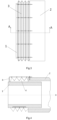
- a conventional immersed tunnel is provided with a first joint segment 1 and a second joint segment 2 during joint construction, wherein the first joint segment 1 is a push-out segment, which can stretch out and draw back in the axial direction X, and the second joint segment 2 is an enlarged segment relatively fixed. As shown in FIG. 4 , the first joint segment 1 is partially located inside the second joint segment 2 and can move axially relative to the second joint segment 2.
- a water stopping device of suspension and sliding type (hereinafter referred to as the water stopping device) is provided, which can be used for waterproofing during the joint construction of an immersed tunnel.
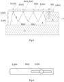
- the water stopping device includes a water stop 3, a first end 301 of the water stop is in sealed connection with the first joint segment 1 and a second end 302 of the water stop is in sealed connection with the second joint segment 2, so as to form a water stopping cavity 4 to prevent the entry of external water.
- the water stop 3 may be made of rubber with certain flexibility and strength, and may also adopt an existing water stop in the prior art.
- the water stop 3 can be an annular structure arranged around the first joint segment 1, with an M-shaped cross section, so as to stretch out and draw back along with the moving of the first joint segment 1.
- the water stop 3 includes flat portions 303 and folded portions 304, wherein one folded portion 304 is formed between every two adjacent flat portions 303 to allow the water stop 3 to stretch out and draw back.
- the flat portion 303 is flat relative to the folded portion 304, is not necessarily a strict flat surface, and mainly refers to a portion not folded significantly.
- a tension rope 5 for limiting overstretching of the water stop 3 may be provided between adjacent flat portions 303.
- the fixed-length tension rope is tightened as the water stop stretches, so as to limit the distance between the folded portions spaced apart and prevent the water stop from being damaged by traction due to overstretching.
- each folded portion 304 is provided with a convex portion 3043 protruding outward and a concave portion 3044 sinking inward.
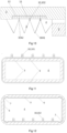
- a support member can be provided at each folded portion 304, which may be a curved plate 6 fitted to the folded portion 304, e.g., adhered to the folded portion 304, so as to support and stabilize the water stop 3.
- an inner surface 601 of the curved plate is fitted to the convex portion 3043
- an outer surface 602 of the curved plate is fitted to the concave portion 3044, as shown in FIGS. 7 to 9 .
- the support members may be provided on both inner and outer sides of the same folded portion 304, and may also be provided at one of the convex portion 3043 and the concave portion 3044. The support members can enhance the support strength of the folded portions and the stability of the water stopping cavity.
- the water stop 3 is annular, and the curved plates 6 may adopt one or more ways in the following embodiments.
- the water stopping device further includes a first rod 8 located outside the water stopping cavity 4.
- One or more first hanging structures 101 are connected to the first rod 8 and the water stop 3, respectively, and are slidably arranged on the first rod 8, to allow the water stop 3 to stretch out and draw back along with the first hanging structures 101 and the first rod 8.
- a first end 801 of the first rod is installed on the first joint segment 1 and can move with the first joint segment 1, while a second end 802 thereof is movably installed on the second joint segment 2.
- the first rod 8 is L-shaped, with a first edge 803 fixedly connected to the first joint segment 1 while a second edge 804 movably connected to a limit device 9 on the second joint segment 2.
- the first edge 803 is a short edge and the second edge 804 is a long edge.
- the present application is not be limited thereto.
- a first hole 901 is formed at the limit device 9 along the axial direction X, the second end 802 or the second edge 804 of the first rod runs through the first hole 901 to move in the axial direction X.
- the first rod 8, in particular its second edge 804, may be long enough to avoid from dropping out from the first hole 901.
- a second long hole 8041 is formed on the second edge 804 of the first rod along the axial direction X, which may be a rectangular hole or an elliptical hole.
- the limit device 9 is provided with a head 902 to confine the second long hole 8041 between the head 902 and the second joint segment 2.
- the second long hole 8041 moves as the water stop 3 and the first rod 8 move, but can move only in the axial direction X due to being confined by the limit device 9.
- a third hole 103 through which the first rod 8 runs is formed at each first hanging structure 101, so that the first hanging structures 101 are installed on the first rod 8 through the third holes 103 and can slide on the first rod 8 along the axial direction X.
- a first end of the first hanging structure 101 is connected to the water stop 3 through the support member.
- the first end of the first hanging structure 101 can be connected to the outer surface 602 of the curved plate, and the inner surface 601 of the curved plate is connected to the first folded portion 3041 of the water stop, so that the first hanging structure 101 is connected to the first folded portion 3041 of the water stop, specifically to the convex portion 3043 of the first folded portion.
- the first hanging structure 101 may also be integrated with or rigidly connected to the curved plate 6, as shown in FIGS. 7 and 8 , to facilitate production and installation on the first rod 8.
- a plurality of first rods 8 are spaced arranged between the first joint segment 1 and the second joint segment 2; and preferably provided on an upper surface and side faces of the first joint segment 1.
- a plurality of first hanging structures 101 are spaced arranged on the same first rod 8 and connected to the corresponding folded portions (the first folded portions) respectively.
- five first rods 8 are spaced arranged on the upper surface of the first joint segment 1, and four first hanging structures are provided on each first rod. It can be understood that the present application is not limited thereto and that a greater or lesser number may be provided as desired.
- the water stop 3 Under the combined action of the first rods 8 and the first hanging structures 101, the water stop 3 can slide in suspension, so that the water stop 3 is less likely to adhere to the surface of the first joint segment 1, and the first joint segment 1 can be stretched more freely to facilitate construction.
- the water stopping device further includes a second rod 11 located in the water stopping cavity 4.
- a groove 12 for installing the second rod 11 is provided at the bottom of the first joint segment 1.
- the second rod 11 can be linear, and one or more second hanging structures 102 are provided thereon.
- the second hanging structures can slide axially on the second rod 11 through a fourth hole of each second hanging structure 102.
- a first end of each second hanging structure 102 is elastically connected to the water stop 3.
- an elastic member (not shown), such as a spring or an elastic rope, is provided between the second hanging structure 102 and the water stop 3, which can allow the second hanging structures 102 and the water stop 3 to move together and also keep the water stop folded.
- the first end of the second hanging structure 102 is elastically connected to the outer surface 602 of the curved plate, and the inner surface 601 of the curved plate is connected to the second folded portion 3042 of the water stop, specifically to the convex portion 3043 of the second folded portion.
- the second rod 11 is provided at the bottom of the first joint segment 1, and can support the folded water stop 3 from the inside, so as to reduce or avoid the water stop 3 from adhering to the first joint segment 1 or falling off to the waterbed.
- a plurality of the second rods 11 can be spaced arranged, and a plurality of second hanging structures 102 respectively connected to the water stop 3 are spaced arranged on each second rod 11, so as to form a firmer bottom-supported structure.
- the first hanging structure 101 and the second hanging structure 102 is of the same structure or have certain similarities, which can be collectively referred to as the hanging structure 10.
- the first hanging structure 101 is mainly connected outside the water stopping cavity to the first rod 8 and the water stop 3, especially to the first folded portions 3041 of the water stop
- the second hanging structure 102 is mainly connected within the water stopping cavity to the second rod 11 and the water stop 3, especially to the second folded portions 3042 of the water stop.
- both the first rods 8 and the second rods 11 can move synchronously with the first joint segment 1, and the water stop 3 can slide in suspension on the first rods 8 and the second rods 11 while moving, so as to keep away from the first joint segment 1.
- an application of a water stopping device of suspension and sliding type is provided, and the water stopping device can be used for waterproofing during the joint construction of immersed tunnel.
- the water stopping device of suspension and sliding type is the water stopping device described in any of the preceding embodiments.
Landscapes
- Engineering & Computer Science (AREA)
- Life Sciences & Earth Sciences (AREA)
- General Life Sciences & Earth Sciences (AREA)
- Mining & Mineral Resources (AREA)
- Paleontology (AREA)
- Civil Engineering (AREA)
- General Engineering & Computer Science (AREA)
- Structural Engineering (AREA)
- Environmental & Geological Engineering (AREA)
- Lining And Supports For Tunnels (AREA)
- Underground Structures, Protecting, Testing And Restoring Foundations (AREA)
- Hydrology & Water Resources (AREA)
Claims (10)
- Dispositif d'arrêt d'eau de type à suspension et à coulissement destiné à être utilisé dans un tunnel immergé, comprenantun arrêt d'eau (3), ayant une première extrémité (301) reliée à un premier segment de jonction (1) du tunnel immergé et pouvant se déplacer axialement avec le premier segment de jonction (1) ; et l'arrêt d'eau (3) ayant en outre une deuxième extrémité (802) reliée à un deuxième segment de jonction (2) ; de manière à former une cavité d'arrêt d'eau (4) ;caractérisé en ce que le dispositif d'arrêt d'eau comprend en outreau moins une première tige (8) ; une première extrémité (801) de la première tige (8) étant reliée au premier segment de jonction (1) et pouvant se déplacer avec le premier segment de j onction (1) ; et une deuxième extrémité (802) de la première tige (8) étant reliée de manière mobile au deuxième segment de jonction (2) ; et comprenant égalementau moins une première structure d'accrochage (101) reliée à l'arrêt d'eau (3) et à la première tige (8) correspondante, et prévue coulissante sur la première tige (8) correspondante.
- Dispositif d'arrêt d'eau de type à suspension et à coulissement selon la revendication 1, dans lequel la première tige (8) est située à l'extérieur de la cavité d'arrêt d'eau (4) ; le dispositif d'arrêt d'eau de type à suspension et à coulissement inclut en outre au moins une deuxième tige (11) située dans la cavité d'arrêt d'eau (4) et prévue sur le premier segment de jonction (1), et au moins une deuxième structure d'accrochage (102) est prévue coulissante sur la deuxième tige (11) et est reliée à l'arrêt d'eau (3) à l'intérieur de la cavité d'arrêt d'eau (4).
- Dispositif d'arrêt d'eau de type à suspension et à coulissement selon la revendication 1 ou 2, dans lequel l'arrêt d'eau (3) présente une section transversale en forme de M et inclut des portions plates (303) et des portions pliées (304), dans lequel une portion pliée (304) est formée entre chaque paire de portions plates (303) adjacentes.
- Dispositif d'arrêt d'eau de type à suspension et à coulissement selon la revendication 3, dans lequel un câble de tension (5) est prévu entre des portions plates (303) adjacentes ; la portion pliée (304) est pourvue d'un élément de support, et l'élément de support est une plaque incurvée (6) ajustée sur la portion pliée (304).
- Dispositif d'arrêt d'eau de type à suspension et à coulissement selon la revendication 3, dans lequel la portion pliée (304) est pourvue d'une plaque incurvée (6) ajustée sur la portion pliée (304) ; l'arrêt d'eau (3) est annulaire ; et les plaques incurvées (6) adoptent l'une ou une combinaison des cinq façons suivantes :première façon, la plaque incurvée (6) est prévue le long d'une circonférence extérieure de la portion pliée (304) de l'arrêt d'eau (3), pour former une bague de support annulaire ;deuxième façon, la plaque incurvée (6) est prévue le long d'une circonférence intérieure de la portion pliée (304) de l'arrêt d'eau (3), pour former une bague de support annulaire ;troisième façon, une sangle de retenue élastique (7) est prévue le long d'une circonférence extérieure de la portion pliée (304) de l'arrêt d'eau (3) ;quatrième façon, plusieurs plaques incurvées (6) sont espacées et agencées le long d'une circonférence extérieure de la portion pliée (304) de l'arrêt d'eau (3), et sont séparées aux coins extérieurs de la cavité d'arrêt d'eau (4) ; et une sangle de retenue élastique (7) est prévue à chaque coin extérieur ;cinquième façon, plusieurs plaques incurvées (6) sont espacées et agencées le long d'une circonférence intérieure de la portion pliée (304) de l'arrêt d'eau (3), et sont séparées aux coins intérieurs de la cavité d'arrêt d'eau (4) ; et une sangle de retenue élastique (7) est prévue à l'extérieur de la cavité d'arrêt d'eau (4) correspondant à chaque position de séparation.
- Dispositif d'arrêt d'eau de type à suspension et à coulissement selon l'une quelconque des revendications 2, 4 et 5, dans lequel la première tige (8) est en forme de L, avec un premier bord (803) relié au premier segment de jonction (1) et un deuxième bord (804) relié mobile à un dispositif de limitation (9) sur le deuxième segment de jonction (2), et la première structure d'accrochage (101) est prévue sur le deuxième bord (804) ; la deuxième tige (11) est linéaire ; le premier segment de joint (1) est pourvu d'une rainure (12), et la deuxième tige (11) est installée dans la rainure (12) ; et la deuxième structure d'accrochage (102) est reliée élastiquement à l'arrêt d'eau (3).
- Dispositif d'arrêt d'eau de type à suspension et à coulissement selon la revendication 6, dans lequel le dispositif de limitation (9) adopte l'un des suivants : premièrement, un premier orifice (901) est formé axialement au niveau du dispositif de limitation (9), et le deuxième bord (804) de la première tige (8) passe à travers le premier orifice (901) ; deuxièmement, un deuxième orifice long (8041) est formé axialement sur le deuxième bord (804) de la première tige (8), le dispositif de limitation (9) est situé dans le deuxième orifice long (8041), et une tête (902) est prévue sur le dispositif de limitation (9) pour éviter que le deuxième orifice long (8041) ne tombe hors du dispositif de limitation (9).
- Dispositif d'arrêt d'eau de type à suspension et à coulissement selon la revendication 3, dans lequel un troisième orifice (103) pour le passage de la première tige (8) est formé au niveau de la première structure d'accrochage (101), et une première extrémité de la première structure d'accrochage (101) est reliée à l'arrêt d'eau (3) par l'intermédiaire d'un élément de support ; un quatrième orifice pour le passage de la deuxième tige (11) est formé au niveau de la deuxième structure d'accrochage (102), et une première extrémité de la deuxième structure d'accrochage (102) est reliée élastiquement à un élément de support installé sur l'arrêt d'eau (3) ; l'élément de support est une plaque incurvée (6), la première extrémité de la première structure d'accrochage (101) et la première extrémité de la deuxième structure d'accrochage (102) sont respectivement reliées à une surface extérieure de la plaque incurvée (6) correspondante, et une surface intérieure de la plaque incurvée (6) est reliée à la portion pliée (304) de l'arrêt d'eau (3) ; et la première structure d'accrochage (101) est intégrée ou reliée de manière rigide à la plaque incurvée (6).
- Dispositif d'arrêt d'eau de type à suspension et à coulissement selon la revendication 7 ou 8, dans lequel une pluralité des premières tiges (8) sont espacées et agencées au moins sur une surface supérieure du premier segment de jonction (1), et une pluralité des premières structures d'accrochage (101) sont espacées et agencées sur la même première tige (8) ; une pluralité des deuxièmes tiges (11) sont espacées et agencées au bas du premier segment de jonction (1), et une pluralité des deuxièmes structures d'accrochage (102) sont espacées et agencées sur la même deuxième tige (11) ; et chaque structure d'accrochage (101, 102) est reliée à la portion pliée (304) correspondante de l'arrêt d'eau (3).
- Application du dispositif d'arrêt d'eau de type à suspension et à coulissement selon l'une quelconque des revendications 1 à 9, où, dans un processus de construction de jonction de fermeture du tunnel immergé à poussée, le dispositif d'arrêt d'eau est capable de se déplacer de manière télescopique avec le premier segment de jonction (1) au cours du processus d'étirement et de retrait.
Applications Claiming Priority (3)
| Application Number | Priority Date | Filing Date | Title |
|---|---|---|---|
| CN202111346603.3A CN114032960B (zh) | 2021-11-15 | 2021-11-15 | 悬滑式止水装置及其应用 |
| CN202111347608.8A CN114000543B (zh) | 2021-11-15 | 2021-11-15 | 环形止水带施工方法 |
| PCT/CN2021/141443 WO2022213672A1 (fr) | 2021-11-15 | 2021-12-27 | Dispositif d'arrêt d'eau de type à coulissement suspendu et son application |
Publications (4)
| Publication Number | Publication Date |
|---|---|
| EP4134486A1 EP4134486A1 (fr) | 2023-02-15 |
| EP4134486A4 EP4134486A4 (fr) | 2024-01-03 |
| EP4134486C0 EP4134486C0 (fr) | 2024-10-30 |
| EP4134486B1 true EP4134486B1 (fr) | 2024-10-30 |
Family
ID=83546005
Family Applications (1)
| Application Number | Title | Priority Date | Filing Date |
|---|---|---|---|
| EP21935888.4A Active EP4134486B1 (fr) | 2021-11-15 | 2021-12-27 | Dispositif d'arrêt d'eau de type à coulissement suspendu et son application |
Country Status (4)
| Country | Link |
|---|---|
| US (1) | US11655608B1 (fr) |
| EP (1) | EP4134486B1 (fr) |
| JP (1) | JP7307863B2 (fr) |
| WO (1) | WO2022213672A1 (fr) |
Families Citing this family (3)
| Publication number | Priority date | Publication date | Assignee | Title |
|---|---|---|---|---|
| CN116291473B (zh) * | 2023-04-06 | 2025-08-22 | 中国电建集团成都勘测设计研究院有限公司 | 装配式抗振井筒结构 |
| CN118326766B (zh) * | 2024-04-03 | 2025-05-27 | 山东岱天工程材料有限公司 | 一种路基止水铜片防护结构 |
| CN119266166B (zh) * | 2024-11-22 | 2025-04-08 | 江苏省水利科学研究院 | 一种水工混凝土施工缝铜止水保护装置及方法 |
Family Cites Families (20)
| Publication number | Priority date | Publication date | Assignee | Title |
|---|---|---|---|---|
| JPS5425294Y2 (fr) * | 1976-03-08 | 1979-08-24 | ||
| JPS54115541A (en) * | 1978-02-28 | 1979-09-08 | Seibu Polymer Kasei Kk | Joint of culvert |
| JPH09203060A (ja) * | 1995-11-24 | 1997-08-05 | Toa Harbor Works Co Ltd | 沈埋トンネルの最終継手施工方法 |
| JP2001152469A (ja) | 1999-11-30 | 2001-06-05 | Ohbayashi Corp | 最終沈埋函の継手方法 |
| JP2002138502A (ja) | 2000-10-31 | 2002-05-14 | Wakachiku Construction Co Ltd | 沈埋函の最終継手函及びこれを用いた最終継手施工法 |
| JP2002364009A (ja) | 2001-06-12 | 2002-12-18 | Taisei Corp | 接合函体及び函体の接続方法 |
| FR2871824B1 (fr) * | 2004-06-17 | 2007-12-07 | Chapsol Sa | Elements-cadres prefabriques pour la realisation de tunnels et de canaux et son application a des bassins de reserve d'eau de type enterre, semi-enterre ou non enterre |
| NL2012765B1 (en) * | 2014-05-06 | 2016-02-23 | Trelleborg Ridderkerk B V | Method for producing a construction element, in particular a tunnel element, having a watertight seal. |
| CN106988346B (zh) | 2017-03-24 | 2019-12-31 | 中国交通建设股份有限公司 | 沉管隧道最终接头及预制方法、安装方法 |
| CN107190777B (zh) | 2017-06-30 | 2020-04-24 | 中交一航局第二工程有限公司 | 沉管隧道最终接头对接系统及对接方法 |
| CN107653910A (zh) * | 2017-08-30 | 2018-02-02 | 中交公路规划设计院有限公司 | 一种滑动体系 |
| CN107700537B (zh) * | 2017-08-30 | 2019-05-03 | 中交公路规划设计院有限公司 | 最终接头的移动止水系统及使用方法 |
| CN107700538B (zh) | 2017-08-30 | 2019-11-05 | 中交公路规划设计院有限公司 | 一种移动式复合止水系统及其使用方法 |
| CN107489169B (zh) * | 2017-08-30 | 2023-05-09 | 中交公路规划设计院有限公司 | 水囊式调压装置及调压方法 |
| CN107700541B (zh) * | 2017-08-31 | 2023-09-26 | 中交四航局第二工程有限公司 | M形止水带保护装置及安装方法 |
| CN108240001B (zh) | 2018-01-29 | 2024-02-02 | 中交第一航务工程局有限公司 | 沉管隧道最终接头及其对接施工方法 |
| CN108385728B (zh) | 2018-05-10 | 2023-05-12 | 中交第一航务工程局有限公司 | 沉管隧道顶推式最终接头及其对接施工方法 |
| CN208363140U (zh) * | 2018-06-21 | 2019-01-11 | 中铁三局集团华东建设有限公司 | 一种地铁车站侧墙钢边止水带的安装结构 |
| CN209854769U (zh) | 2019-04-11 | 2019-12-27 | 北京九州动脉隧道技术有限公司 | 一种水下沉管用管道接头装置 |
| CN113309146B (zh) * | 2021-05-31 | 2023-01-20 | 中交第一航务工程局有限公司 | 一种最终接头止水装置及安装方法 |
-
2021
- 2021-12-27 JP JP2022575327A patent/JP7307863B2/ja active Active
- 2021-12-27 WO PCT/CN2021/141443 patent/WO2022213672A1/fr not_active Ceased
- 2021-12-27 EP EP21935888.4A patent/EP4134486B1/fr active Active
-
2022
- 2022-12-06 US US18/076,243 patent/US11655608B1/en active Active
Also Published As
| Publication number | Publication date |
|---|---|
| US20230151579A1 (en) | 2023-05-18 |
| WO2022213672A1 (fr) | 2022-10-13 |
| EP4134486C0 (fr) | 2024-10-30 |
| EP4134486A4 (fr) | 2024-01-03 |
| EP4134486A1 (fr) | 2023-02-15 |
| US11655608B1 (en) | 2023-05-23 |
| JP2023526138A (ja) | 2023-06-20 |
| JP7307863B2 (ja) | 2023-07-12 |
Similar Documents
| Publication | Publication Date | Title |
|---|---|---|
| US11655608B1 (en) | Water stopping device of suspension and sliding type and an application thereof | |
| JP6588775B2 (ja) | ジャッキ装置及びジャッキ方法 | |
| CN219509965U (zh) | 一种具有弹性阻尼结构的伸缩杆 | |
| CN208845613U (zh) | 异形弹簧 | |
| CN114484102B (zh) | 一种变径式油管接箍 | |
| CN114032960B (zh) | 悬滑式止水装置及其应用 | |
| CN207739740U (zh) | 一种施工检修用便于携带式安全遮栏 | |
| CN207018415U (zh) | 一种易安装缓冲件、缓冲机构及减震器 | |
| CN114517836B (zh) | 一种复合式遇水膨胀橡胶圈 | |
| CN206964832U (zh) | 一种医疗服务系统移动支架 | |
| CN205770976U (zh) | 一种用于柔性风管的夹持机构 | |
| CN206157747U (zh) | 巨型环状钢吊箱围堰结构 | |
| CN201553215U (zh) | 一种厢式车用的连接装置 | |
| CN115162411A (zh) | 双插式沉管接头及施工方法 | |
| CN216496755U (zh) | 一种胃肠外科护理用胃肠液减压装置 | |
| CN216426472U (zh) | 一种软体罐防护吊装网 | |
| CN217891314U (zh) | 一种用于生产空心预制构件的芯模和模具 | |
| CN204196586U (zh) | 一种脚轮连接结构 | |
| CN208243584U (zh) | 肛门盘式拉钩 | |
| CN215763709U (zh) | 一种液压管 | |
| CN218894223U (zh) | 现浇混凝土水平施工缝止水结构 | |
| CN206786011U (zh) | 一种液压机密封件 | |
| CN221879503U (zh) | 矿山巡检装置 | |
| CN201726081U (zh) | 用于电缆管的防电缆刮擦接头 | |
| CN110925498A (zh) | 一种新型带注塑接头的pe-c管 |
Legal Events
| Date | Code | Title | Description |
|---|---|---|---|
| STAA | Information on the status of an ep patent application or granted ep patent |
Free format text: STATUS: THE INTERNATIONAL PUBLICATION HAS BEEN MADE |
|
| PUAI | Public reference made under article 153(3) epc to a published international application that has entered the european phase |
Free format text: ORIGINAL CODE: 0009012 |
|
| STAA | Information on the status of an ep patent application or granted ep patent |
Free format text: STATUS: REQUEST FOR EXAMINATION WAS MADE |
|
| 17P | Request for examination filed |
Effective date: 20221109 |
|
| AK | Designated contracting states |
Kind code of ref document: A1 Designated state(s): AL AT BE BG CH CY CZ DE DK EE ES FI FR GB GR HR HU IE IS IT LI LT LU LV MC MK MT NL NO PL PT RO RS SE SI SK SM TR |
|
| A4 | Supplementary search report drawn up and despatched |
Effective date: 20231204 |
|
| RIC1 | Information provided on ipc code assigned before grant |
Ipc: E02D 29/067 20060101ALI20231128BHEP Ipc: E02D 29/063 20060101ALI20231128BHEP Ipc: E02D 19/02 20060101ALI20231128BHEP Ipc: E02D 29/16 20060101ALI20231128BHEP Ipc: E02D 29/073 20060101AFI20231128BHEP |
|
| DAV | Request for validation of the european patent (deleted) | ||
| DAX | Request for extension of the european patent (deleted) | ||
| GRAP | Despatch of communication of intention to grant a patent |
Free format text: ORIGINAL CODE: EPIDOSNIGR1 |
|
| STAA | Information on the status of an ep patent application or granted ep patent |
Free format text: STATUS: GRANT OF PATENT IS INTENDED |
|
| INTG | Intention to grant announced |
Effective date: 20240621 |
|
| GRAS | Grant fee paid |
Free format text: ORIGINAL CODE: EPIDOSNIGR3 |
|
| GRAA | (expected) grant |
Free format text: ORIGINAL CODE: 0009210 |
|
| STAA | Information on the status of an ep patent application or granted ep patent |
Free format text: STATUS: THE PATENT HAS BEEN GRANTED |
|
| AK | Designated contracting states |
Kind code of ref document: B1 Designated state(s): AL AT BE BG CH CY CZ DE DK EE ES FI FR GB GR HR HU IE IS IT LI LT LU LV MC MK MT NL NO PL PT RO RS SE SI SK SM TR |
|
| REG | Reference to a national code |
Ref country code: GB Ref legal event code: FG4D |
|
| REG | Reference to a national code |
Ref country code: CH Ref legal event code: EP |
|
| REG | Reference to a national code |
Ref country code: IE Ref legal event code: FG4D |
|
| REG | Reference to a national code |
Ref country code: DE Ref legal event code: R096 Ref document number: 602021021222 Country of ref document: DE |
|
| U01 | Request for unitary effect filed |
Effective date: 20241104 |
|
| U07 | Unitary effect registered |
Designated state(s): AT BE BG DE DK EE FI FR IT LT LU LV MT NL PT RO SE SI Effective date: 20241114 |
|
| U20 | Renewal fee for the european patent with unitary effect paid |
Year of fee payment: 4 Effective date: 20241127 |
|
| PG25 | Lapsed in a contracting state [announced via postgrant information from national office to epo] |
Ref country code: HR Free format text: LAPSE BECAUSE OF FAILURE TO SUBMIT A TRANSLATION OF THE DESCRIPTION OR TO PAY THE FEE WITHIN THE PRESCRIBED TIME-LIMIT Effective date: 20241030 Ref country code: IS Free format text: LAPSE BECAUSE OF FAILURE TO SUBMIT A TRANSLATION OF THE DESCRIPTION OR TO PAY THE FEE WITHIN THE PRESCRIBED TIME-LIMIT Effective date: 20250228 |
|
| PG25 | Lapsed in a contracting state [announced via postgrant information from national office to epo] |
Ref country code: ES Free format text: LAPSE BECAUSE OF FAILURE TO SUBMIT A TRANSLATION OF THE DESCRIPTION OR TO PAY THE FEE WITHIN THE PRESCRIBED TIME-LIMIT Effective date: 20241030 |
|
| PG25 | Lapsed in a contracting state [announced via postgrant information from national office to epo] |
Ref country code: NO Free format text: LAPSE BECAUSE OF FAILURE TO SUBMIT A TRANSLATION OF THE DESCRIPTION OR TO PAY THE FEE WITHIN THE PRESCRIBED TIME-LIMIT Effective date: 20250130 |
|
| PG25 | Lapsed in a contracting state [announced via postgrant information from national office to epo] |
Ref country code: GR Free format text: LAPSE BECAUSE OF FAILURE TO SUBMIT A TRANSLATION OF THE DESCRIPTION OR TO PAY THE FEE WITHIN THE PRESCRIBED TIME-LIMIT Effective date: 20250131 |
|
| PG25 | Lapsed in a contracting state [announced via postgrant information from national office to epo] |
Ref country code: PL Free format text: LAPSE BECAUSE OF FAILURE TO SUBMIT A TRANSLATION OF THE DESCRIPTION OR TO PAY THE FEE WITHIN THE PRESCRIBED TIME-LIMIT Effective date: 20241030 |
|
| PG25 | Lapsed in a contracting state [announced via postgrant information from national office to epo] |
Ref country code: RS Free format text: LAPSE BECAUSE OF FAILURE TO SUBMIT A TRANSLATION OF THE DESCRIPTION OR TO PAY THE FEE WITHIN THE PRESCRIBED TIME-LIMIT Effective date: 20250130 |
|
| U1N | Appointed representative for the unitary patent procedure changed after the registration of the unitary effect |
Representative=s name: METIDA; LT |
|
| PG25 | Lapsed in a contracting state [announced via postgrant information from national office to epo] |
Ref country code: SM Free format text: LAPSE BECAUSE OF FAILURE TO SUBMIT A TRANSLATION OF THE DESCRIPTION OR TO PAY THE FEE WITHIN THE PRESCRIBED TIME-LIMIT Effective date: 20241030 |
|
| PG25 | Lapsed in a contracting state [announced via postgrant information from national office to epo] |
Ref country code: MC Free format text: LAPSE BECAUSE OF FAILURE TO SUBMIT A TRANSLATION OF THE DESCRIPTION OR TO PAY THE FEE WITHIN THE PRESCRIBED TIME-LIMIT Effective date: 20241030 |
|
| PG25 | Lapsed in a contracting state [announced via postgrant information from national office to epo] |
Ref country code: SK Free format text: LAPSE BECAUSE OF FAILURE TO SUBMIT A TRANSLATION OF THE DESCRIPTION OR TO PAY THE FEE WITHIN THE PRESCRIBED TIME-LIMIT Effective date: 20241030 |
|
| PG25 | Lapsed in a contracting state [announced via postgrant information from national office to epo] |
Ref country code: CZ Free format text: LAPSE BECAUSE OF FAILURE TO SUBMIT A TRANSLATION OF THE DESCRIPTION OR TO PAY THE FEE WITHIN THE PRESCRIBED TIME-LIMIT Effective date: 20241030 |
|
| REG | Reference to a national code |
Ref country code: CH Ref legal event code: PL |
|
| PLBE | No opposition filed within time limit |
Free format text: ORIGINAL CODE: 0009261 |
|
| STAA | Information on the status of an ep patent application or granted ep patent |
Free format text: STATUS: NO OPPOSITION FILED WITHIN TIME LIMIT |
|
| 26N | No opposition filed |
Effective date: 20250731 |
|
| PG25 | Lapsed in a contracting state [announced via postgrant information from national office to epo] |
Ref country code: CH Free format text: LAPSE BECAUSE OF NON-PAYMENT OF DUE FEES Effective date: 20241231 |
|
| PG25 | Lapsed in a contracting state [announced via postgrant information from national office to epo] |
Ref country code: IE Free format text: LAPSE BECAUSE OF NON-PAYMENT OF DUE FEES Effective date: 20241227 |
|
| U20 | Renewal fee for the european patent with unitary effect paid |
Year of fee payment: 5 Effective date: 20251127 |