EP4134488A1 - Roue de fraise - Google Patents
Roue de fraise Download PDFInfo
- Publication number
- EP4134488A1 EP4134488A1 EP21191256.3A EP21191256A EP4134488A1 EP 4134488 A1 EP4134488 A1 EP 4134488A1 EP 21191256 A EP21191256 A EP 21191256A EP 4134488 A1 EP4134488 A1 EP 4134488A1
- Authority
- EP
- European Patent Office
- Prior art keywords
- tooth
- cutting
- milling
- head
- wheel
- Prior art date
- Legal status (The legal status is an assumption and is not a legal conclusion. Google has not performed a legal analysis and makes no representation as to the accuracy of the status listed.)
- Granted
Links
Images



Classifications
-
- E—FIXED CONSTRUCTIONS
- E02—HYDRAULIC ENGINEERING; FOUNDATIONS; SOIL SHIFTING
- E02D—FOUNDATIONS; EXCAVATIONS; EMBANKMENTS; UNDERGROUND OR UNDERWATER STRUCTURES
- E02D17/00—Excavations; Bordering of excavations; Making embankments
- E02D17/13—Foundation slots or slits; Implements for making these slots or slits
-
- E—FIXED CONSTRUCTIONS
- E02—HYDRAULIC ENGINEERING; FOUNDATIONS; SOIL SHIFTING
- E02F—DREDGING; SOIL-SHIFTING
- E02F3/00—Dredgers; Soil-shifting machines
- E02F3/04—Dredgers; Soil-shifting machines mechanically-driven
- E02F3/18—Dredgers; Soil-shifting machines mechanically-driven with digging wheels turning round an axis, e.g. bucket-type wheels
- E02F3/22—Component parts
- E02F3/24—Digging wheels; Digging elements of wheels; Drives for wheels
- E02F3/241—Digging wheels; Digging elements of wheels; Drives for wheels digging wheels
-
- E—FIXED CONSTRUCTIONS
- E02—HYDRAULIC ENGINEERING; FOUNDATIONS; SOIL SHIFTING
- E02F—DREDGING; SOIL-SHIFTING
- E02F9/00—Component parts of dredgers or soil-shifting machines, not restricted to one of the kinds covered by groups E02F3/00 - E02F7/00
- E02F9/28—Small metalwork for digging elements, e.g. teeth scraper bits
- E02F9/2866—Small metalwork for digging elements, e.g. teeth scraper bits for rotating digging elements
Definitions
- the invention relates to a cutting wheel for a trench wall cutter with a drum-shaped hub, on the outer circumference of which plate-shaped tooth holders are arranged in at least one circumferential row, in which cutting teeth for removing soil are detachably held, according to the preamble of claim 1.
- a generic cutting wheel is, for example, from EP 2 685 007 A1 out.
- This known cutting wheel has ring-segment-like tooth mounts along several circumferential rows, which are attached to the drum-shaped hub in an axially offset manner with respect to one another.
- Each arcuate tooth holder has a large number of removal teeth, which have a different position in relation to one another.
- the individual removal teeth protrude to different extents from the tooth holder in order to cover the widest possible area of the in-situ soil with the cutting bodies on the individual removal teeth. In this way, good soil removal can be achieved.
- a total of six circumferential rows of tooth mounts are provided, each with a plurality of teeth arranged. If a soil layer with cohesive soil, such as clay or loam, is processed with such a cutting wheel, the cohesive soil material can adhere to the curved tooth holders and accumulate in the spaces between the teeth. As a result, the milling wheel is clogged overall, which significantly reduces the removal rate during milling. In addition, a clogged milling wheel tends to run off, making it difficult to create a milling slot in a precise position.
- the invention is based on the object of specifying a cutting wheel for a trench wall cutter, with which efficient cutting is made possible even with different soil layers.
- the cutting wheel according to the invention is characterized in that at least one cutting tooth is provided with a tooth head extending transversely on both sides of the tooth base, that the tooth head has a lateral first head area and a lateral second head area, which extend in opposite directions to one another, and that on at least two adjacent cutting bodies are arranged in each head area.
- a basic idea of the invention is to provide one or more cutting teeth in a cutting wheel, which are T-shaped in the circumferential direction when viewed from above, which cutting teeth have a tooth head extending transversely with a plurality of cutting bodies.
- a larger width of the in-situ soil can be processed by removing material with a single cutter tooth.
- This makes it possible to reduce the number of necessary milling teeth and thus also the number of necessary tooth holders in a circumferential row and distributed over the milling hub.
- a free space between the cutting teeth and the adjacent tooth holders increases considerably, which in turn greatly reduces the possibility of sticking of cohesive soil material and considerably facilitates stripping of sticking soil material.
- the width of the tooth crest can be a multiple, in particular up to three, four or five times or more, of the width of the tooth root.
- the two head areas can be designed symmetrically or asymmetrically to one another be.
- At least one cutting body is preferably arranged in the middle between the two head regions.
- the preferred embodiment of the invention is that all cutting elements on the tooth head are directed forwards in a cutting direction.
- the cutting bodies can achieve a particularly good and uniform removal rate.
- the cutting bodies can be designed to be identical to one another.
- the cutting bodies are hard metal bodies that are soldered into the tooth head.
- the head regions with the cutting bodies are offset from one another in the circumferential direction or are arranged in a cutting line.
- the line can be straight or curved.
- the cutting bodies are preferably arranged relative to one another in such a way that they have the same radial distance to the axis of rotation or center axis of the hub of the cutting wheel and the head areas are symmetrical to a center plane of the cutting tooth. If the two head areas are arranged offset in the circumferential direction, one head area can lead during removal while the other head area can lag behind.
- the cutting head it is expedient for the cutting head to have a sweep in the cutting direction and for the cutting bodies to form a V-shaped arrangement on the cutting head.
- the following cutting bodies can be arranged offset evenly to the rear in the milling direction.
- the cutting bodies can be designed differently from one another. According to a further development of the invention, it is particularly advantageous for the cutting bodies to be of identical design and in particular to have one cutting edge.
- the end faces of the cutting bodies have one or more linear cutting edges, which allow a high removal rate in both soft and hard soil layers.
- the use of the same cutting bodies reduces manufacturing and repair costs.
- the cutting bodies are formed in particular from a high-strength hard metal.
- any number of peripheral rows for the tooth mounts on the drum-shaped hub can be provided, provided there is a sufficient distance between the peripheral rows.
- the axial distance between the circumferential rows is preferably between 20 cm and 50 cm.
- a distance between the individual tooth holders in a circumferential row in a circumferential direction is between 20 cm and 150 cm.
- the number of tooth mounts in a circumferential row basically depends on the size of the hub on which they are fitted.
- the individual tooth holders are preferably arranged at a predetermined equal angular distance from one another, in particular 60, 90, 120 or 180 degrees.
- an outer circumferential row is arranged on a free outside of the gear wheel, an inner circumferential row is arranged on an inside of the cutting wheel facing a bearing plate, and at least one central circumferential row is arranged.
- the individual circumferential rows can be designed differently from one another.
- one or more foldable teeth so-called folding teeth, can be mounted on the inner peripheral row, which can be pivoted into a position below a cutting shield on which the cutting wheel is mounted during milling operation.
- the approximately T-shaped cutting tooth or teeth are preferably arranged only in the one or more middle circumferential rows, which are positioned in the axial direction between the outer circumferential row and the inner circumferential row.
- L-shaped milling teeth can be provided on the outer circumferential row and/or the inner circumferential row with only one head region extending transversely to the tooth base.
- the head areas each extend inwards to the at least one central circumferential row.
- the number of middle circumferential rows depends on the axial length of the drum-shaped hub and thus depends on the planned milling width.
- a particularly expedient design of a cutting wheel that is easy to clean consists in the fact that only two central peripheral rows are arranged.
- particularly large free spaces can be achieved on the cutting wheel by providing only two tooth holders with cutting teeth in the at least one central circumferential row, which are arranged offset by 180° from one another on the circumference of the hub. If there are several central circumferential rows, the arrangements of the individual circumferential rows can be arranged at an offset angle relative to one another. In the case of two central circumferential rows, the offset angle can be 90° to one another, and in the case of three central circumferential rows, 60° to one another. This counteracts chattering during milling. In particular, this means that the plate-shaped milling holders in two adjacent circumferential rows are not directly next to one another in the axial direction. As a result, the distances and thus the free spaces between the individual tooth holders are further increased, which counteracts the attachment of soil material and further improves the possibility of stripping off attached material or cleaning.
- a removal rate of a cutting wheel can be improved in particular by arranging at least one collapsible cutting tooth on the inner peripheral side.
- the folding tooth can be swung out during a rotation in an area below the bearing plate, which lies between two milling wheels and keeps them rotating, in order to remove soil material directly below the bearing plate.
- any number of milling teeth and tooth holders can be provided on the outer circumferential row. It is preferred that the number of cutting teeth and tooth holders in the outer circumferential row is greater than the number in a middle circumferential row. It is particularly preferred that twice as many tooth holders are arranged on the outer circumferential row as in a middle circumferential row. In principle, it is also possible to use double adapters on the outside. Experience has shown that the use of individual, inclined adapters reduces wear on the milling tooth itself and on the adapters.
- a further cutting wheel according to the invention for a trench wall cutter with a drum-shaped hub, on the outer circumference of which plate-shaped tooth holders are arranged in at least one circumferential row, in which cutting teeth for removing soil are detachably held, is characterized in that on the outer circumference of the hub two plate-shaped tooth holders are attached to one another in the axial direction are arranged adjacent to form a double tooth holder and that in the first tooth holder a first cutting tooth and in the second tooth holder a second cutting tooth are accommodated and held.
- Conventional tooth holders can be used, which can absorb higher forces due to their doubling.
- a preferred development consists in the first milling tooth being designed as a first tooth half and the second milling tooth as a second tooth half, which together form an overall tooth. If only one half of the tooth is damaged only this needs to be changed. This further reduces the maintenance effort.
- the first half of the tooth is L-shaped with a tooth base for holding in the first tooth holder and a tooth crest with a lateral tip region which extends away to one side transversely to the tooth base
- the second half of the tooth is L-shaped is formed with a tooth root for holding in the second tooth holder and a tooth crest with a lateral tip portion which extends transversely to the tooth root to an opposite side.
- the two L-shaped tooth halves are mirror-symmetrical to one another, at least in their head area.
- a deflector element is arranged, through which soil material can be diverted into a side region of the tooth holders. This protects the tooth holder.
- the invention further includes a milling tooth, which is characterized in that the milling tooth is formed with a tooth head extending transversely on both sides of the tooth base, that the tooth head has a lateral first head region and a lateral second head region, which extend in opposite directions to one another , and that at least two adjacent cutting bodies are arranged on each head area.
- the cutting tooth according to the invention can be used in particular in the cutting wheel according to the invention described above, with the advantages described here resulting.
- a preferred further development of the cutting tooth is that it has a first tooth half and a second tooth half which are detachably connected to one another to form the cutting tooth.
- the detachable connection can in particular at least one connecting element, in particular a connecting bolt or a screw.
- a detachable connection can also include a simple tack weld.
- the two halves of the tooth are preferably designed to be mirror-symmetrical to one another.
- the tooth halves each have a tooth base and a head area.
- a particularly expedient configuration of the cutting tooth according to the invention consists in that the first half of the tooth is L-shaped with a tooth base and a tooth head with a lateral head area which extends away to one side transversely to the tooth base, and that the second tooth half is L-shaped is formed with a tooth root and a tooth crest with a lateral head portion which extends transversely to the tooth root to an opposite side.
- the milling power is roughly evenly distributed over both halves of the tooth during milling.
- the milling tooth has a tooth base for insertion into the tongue-shaped recess on the tooth holding arm and a tooth head with at least one cutting body.
- a conventional milling tooth can be used in the folding tooth arrangement, which reduces the maintenance effort.
- a particularly simple attachment of the tooth can be achieved in that the milling tooth is attached in the tooth holding arm in the area of the tooth base via at least one transverse attachment bolt, which extends transversely to a longitudinal direction of the tooth base, and that in the strip element at least one through hole for the attachment bolt is provided.
- an advantageous folding tooth consists in the fact that the strip element is arranged on the tooth holding arm on the side which faces away from a bearing plate on which the cutting wheel is mounted.
- the invention relates to a trench wall cutter with a cutter frame, on the underside of which at least one bearing plate is arranged, with at least one cutting wheel according to the invention being mounted on the bearing plate, as has been described above.
- stripping elements are attached to the milling machine frame, which protrude into an intermediate space between the circumferential rows with the tooth holders with the milling teeth for scraping off adhering soil material.
- the stripping elements can in particular be designed like paddles with a wide stripping blade and a thin holding web arranged on it.
- the web is relatively thin and preferably has a width of between 1 cm and 3 cm.
- the distance between the tooth holders and two adjacent circumferential rows is determined by the size of the cantilevered head area on a T-shaped tooth and the width of the retaining bar of a stripping element with a slight distance between the outer edge of the cutting teeth and the retaining bar of an intermediate stripping element.
- an advantageous embodiment of a trench wall cutter according to the invention consists in the fact that a total of four cutting wheels are provided, which are mounted in pairs on a bearing plate each.
- the end shield is arranged on an underside of the milling frame.
- the milling wheels can be driven either by a hub motor or preferably by one or more drive motors on the milling machine frame, with a torque being transmitted via a corresponding gear arrangement on the respective bearing plate.
- a trench wall cutter 10 according to the invention is shown schematically in FIGS Figures 1 and 2 shown, with only a lower part of a cutter frame 12 with only a single cutting wheel 30 are shown. Overall, however, four cutting wheels 30 are arranged on the trench wall cutter 10, two of which are mounted as a pair of cutting wheels on both sides of a bearing plate 20 so as to be rotatable about a bearing axis 22.
- a box-like suction nozzle 14 with a plurality of suction openings 16 for sucking off the milled soil material with the surrounding suspension is arranged on an underside of the milling machine frame 12.
- For suction is on an in 1 Flange 18 shown mounted a suction pump, not shown.
- the construction of a cutting wheel 30 according to the invention is described below in connection with the Figures 3 to 5 explained.
- the cutting wheel 30 has a drum-shaped hub 32, on the outer circumference of which tooth holders 40 with cutting teeth 50 are arranged in circumferential rows.
- pivot bearings 80 for folding teeth 70 can be arranged in addition to normal tooth mounts 40.
- individual tooth mounts 40 can be arranged at an angle of inclination with respect to a radially directed plane.
- two central circumferential rows with a double arrangement of tooth holders 40 for receiving cutting teeth 50 according to the invention with a T-shaped tooth head 60 are arranged between the inner circumferential row and the outer circumferential row.
- the tooth mounts 40 and the cutting teeth 50 will be explained in more detail below.
- two double tooth holders 40 are arranged in the two central circumferential rows, which are offset by 180° in the same circumferential row.
- the tooth mounts 40 are in turn offset by 90° to the second central circumferential row, so that there is a sufficient distance between the individual tooth mounts 40 in the adjacent circumferential rows.
- a total of four inclined tooth mounts 40 are arranged with an outward inclination.
- two folding teeth 70 are arranged offset by 180° with respect to one another. Offset from this by 90°, two double tooth holders 40 are also arranged on the inner circumferential row, which are also offset by 180° to one another.
- the double tooth holding arrangement each with two plate-shaped tooth holders 40, which adjoin directly next to each other, are in the direction of rotation of the cutting wheel 30 beveled deflector elements 46 upstream to a penetration of To avoid soil material in a gap between the two adjacent tooth mounts 40.
- U-shaped recesses 41 are introduced in the tooth holders 40, in which the milling teeth 50 are held directly or via a U-shaped insert 42.
- the plate-shaped tooth mounts 40 can thus be attached to the hub 32 of the cutting wheel 30 in a single arrangement as in the outer circumferential row or in a double arrangement as in the two middle circumferential rows.
- a single tooth mount 40 is plate-shaped and has an arcuate edge on its underside for welding to the outer periphery of the hub 32 of a cutter wheel 30 . Furthermore, a U-shaped recess 41 is provided, into which a tooth base 52 of a milling tooth 50 can be radially inserted in a manner known in principle, forming a tongue and groove connection.
- a fastening pin 44 can be pushed transversely through a through-hole 53 in the tooth root 52 of the milling tooth 50, with which the milling tooth 50 used is fixed to the tooth holder 40 in a positive and non-positive manner.
- the fastening pin 44 can in particular be designed as a slotted sleeve which is fixed in the through-hole 53 with a certain clamping force.
- two plate-shaped tooth holders 40 are arranged directly next to one another in order to absorb particularly high forces.
- the two adjoining tooth holders 40 can also be easily detachably connected to one another via fastening screws or spot welds.
- a single cutter 50 with two corresponding dedendums 52 or two individual cutters 50 with a single dedendum can be used, which together can form an overall tooth.
- a strip-shaped deflector element 46 is arranged upstream of the double arrangement of tooth mounts 40 , which is welded to the milling wheel hub 32 and/or to the tooth mounts 40 .
- the deflector element 46 prevents milled soil material from penetrating into the joint between the two adjacent tooth mounts 40, thereby increasing the stability of the double arrangement. Furthermore, the deflection element 46 can have one or more inclined deflection surfaces, with which soil material hitting the front is deflected laterally around the tooth holders 40 . As a result, the load on the tooth holders 40 is further reduced and a certain guidance of the milled soil material to the outside or to the suction openings 16 of the suction connection 14 of the trench wall cutter 10 can also be achieved.
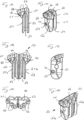
- a first cutting tooth 50 according to the invention which can also be provided as a cutting tooth half 51, is shown schematically in FIGS Figures 10 and 11 shown.
- the approximately L-shaped milling tooth 50 has a tongue-shaped tooth base 52 and a tooth head 60 with a first head region 61 that projects to one side.
- On the first head area 61 three adjacent cutting bodies 66 with linear cutting edges for removing soil material are arranged next to one another.
- a circumferential groove 54 with an approximately V-shaped cross-section is formed along an outer side of the tooth base 52, which when inserted into a U-shaped recess on a tooth holder with a corresponding spring-like projection provides a tongue and groove connection for holding the tooth 50 in the tooth holder .
- a transverse through-hole 53 is formed in the tooth base 52, into which a fastening pin 44 can be inserted.
- FIG. 12 to 15 Another cutting tooth 50 according to the invention is shown, which is formed from two tooth halves 51a and 51b by detachably connecting the two tooth halves 51a, 51b.
- the detachable connection can include screwing or tack welding, for example.
- a first tooth half 51a can correspond to the tooth half 51 according to the Figures 10 and 11 be trained.
- the second half of the tooth 51b can be mirror-symmetrical to the first half of the tooth 51a, wherein a cutting tooth 50 with a tooth head 60 that is approximately T-shaped in cross section or when viewed from the front is formed.
- the tooth tip 60 has a first tip region 61 which extends laterally beyond the tooth root 52 to a first side.
- three cutting bodies 66 are arranged in a sloping line on the first head region 61 of the tooth head 60 .
- the second head region 62 protrudes laterally in the opposite direction in relation to the tooth base 52, with three cutting bodies 66 also being arranged in a sloping line.
- the cutting bodies 66 with the arrangement sloping outwards and backwards in the milling direction form a sweep of the entire milling tooth 50, which together with the T-shaped contour of the head regions 61, 62 of the milling tooth 50 extending on both sides to form a particularly contributes to a good removal rate.
- the formation of the entire cutting tooth 50 by a first cutting tooth half 51a and a second cutting tooth half 51b which is mirror-symmetrical thereto creates a common double tooth base 52 with a total of two circumferential grooves 54 .
- This allows the cutting tooth 50 to be mounted in a dual array of tooth mounts 40 .
- large forces can be absorbed by the double tooth holder 40 even if the tooth crest 60 projects far beyond the tooth root 52 .
- the invention further relates to a folding tooth 70, which in the Figures 16 to 20 is shown.
- the folding tooth 70 is pivotally mounted on a pivot bearing 80 of a cutting wheel 30, as is clearly shown in FIGS Figures 3 to 5 is shown.
- the folding tooth 70 can assume a folded position and an unfolded position.
- the folding tooth 70 is in the unfolded position when it is outside the peripheral area of the bearing plate 20 in order to remove soil material underneath the bearing plate 20 .
- the hinged tooth 70 sweeps directly past the bearing plate 20 of a trench wall cutter 10
- the hinged tooth 70 is pivoted into a folded-in position by a basically known connecting link control on the bearing plate 20 in order to avoid damage to the bearing plate 20.
- the folding tooth 70 has a pivoting body 71 with a control arm 73 pointing downwards and a tooth holding arm 74 pointing upwards.
- Two bearing eyes 72 are provided between the control arm 73 and the tooth holding arm 74 for receiving a pivot bolt of the pivot bearing 80 on the cutting wheel 30 .
- a wear plate 75 can be attached to the control arm 73, which is in contact with a connecting link of a link control on the bearing plate 20, through which the pivoting position of the folding tooth 70 is predetermined.
- a U-shaped recess 41 is provided on the tooth holding arm 74 in a manner known in principle, into which, in a known manner, about the milling tooth 50 described above according to FIG Figures 10 and 11 or any other milling tooth with a corresponding tongue-shaped tooth base 52 is inserted.
- a through-hole 53 on the tooth base 52 can be used to fix the position of the milling tooth 50 on the tooth holding arm 74 by means of a fastening pin.
- a strip element 76 is attached, in particular screwed or welded, to at least one side of the tooth holding arm 74 .
- the strip element 76 is located in particular on the side that faces away from the bearing plate 20 on a trench cutter 10 .
- the strip element 76 covers and fills up a basically existing dead space, which is functionally formed by the pivoting movement of the hinged tooth 70 in a purely plate-shaped design of the tooth holding arm 74 .
- cohesive soil material could adhere to the hinged tooth 70 in this dead space, as a result of which the functioning of the hinged tooth 70 can be impaired.
- this dead space is filled up so that no or only a small amount of adhesive soil material can then adhere to the hinged tooth 70 .
- a cutting wheel can be created which is particularly suitable for removing cohesive layers of soil, the adhesion of soil material being avoided or at least greatly reduced by the various measures.
- the individual measures can be provided in combination with one another or also individually.
Landscapes
- Engineering & Computer Science (AREA)
- Mining & Mineral Resources (AREA)
- Civil Engineering (AREA)
- General Engineering & Computer Science (AREA)
- Structural Engineering (AREA)
- Mechanical Engineering (AREA)
- Life Sciences & Earth Sciences (AREA)
- General Life Sciences & Earth Sciences (AREA)
- Paleontology (AREA)
- Milling Processes (AREA)
Priority Applications (7)
| Application Number | Priority Date | Filing Date | Title |
|---|---|---|---|
| EP21191256.3A EP4134488B1 (fr) | 2021-08-13 | 2021-08-13 | Roue de fraise |
| PCT/EP2022/071084 WO2023016809A1 (fr) | 2021-08-13 | 2022-07-27 | Roue de coupe |
| CN202280051917.7A CN117693621A (zh) | 2021-08-13 | 2022-07-27 | 铣切轮 |
| KR1020247002024A KR20240021980A (ko) | 2021-08-13 | 2022-07-27 | 밀링 휠 |
| EP22760973.2A EP4409073A1 (fr) | 2021-08-13 | 2022-08-04 | Roue de coupe |
| PCT/EP2022/071954 WO2023016915A1 (fr) | 2021-08-13 | 2022-08-04 | Roue de coupe |
| KR1020247002965A KR20240025667A (ko) | 2021-08-13 | 2022-08-04 | 커팅 휠 |
Applications Claiming Priority (1)
| Application Number | Priority Date | Filing Date | Title |
|---|---|---|---|
| EP21191256.3A EP4134488B1 (fr) | 2021-08-13 | 2021-08-13 | Roue de fraise |
Publications (3)
| Publication Number | Publication Date |
|---|---|
| EP4134488A1 true EP4134488A1 (fr) | 2023-02-15 |
| EP4134488C0 EP4134488C0 (fr) | 2024-03-06 |
| EP4134488B1 EP4134488B1 (fr) | 2024-03-06 |
Family
ID=77338543
Family Applications (1)
| Application Number | Title | Priority Date | Filing Date |
|---|---|---|---|
| EP21191256.3A Active EP4134488B1 (fr) | 2021-08-13 | 2021-08-13 | Roue de fraise |
Country Status (2)
| Country | Link |
|---|---|
| EP (1) | EP4134488B1 (fr) |
| WO (1) | WO2023016809A1 (fr) |
Cited By (2)
| Publication number | Priority date | Publication date | Assignee | Title |
|---|---|---|---|---|
| US20240035252A1 (en) * | 2022-07-28 | 2024-02-01 | Bauer Maschinen Gmbh | Trench cutter and method for forming a cut trench in the ground |
| WO2024199776A1 (fr) * | 2023-03-30 | 2024-10-03 | Liebherr-Werk Nenzing Gmbh | Procédé de réparation d'un ensemble outil de coupe |
Citations (7)
| Publication number | Priority date | Publication date | Assignee | Title |
|---|---|---|---|---|
| JPS5746611U (fr) * | 1980-08-26 | 1982-03-15 | ||
| US4666214A (en) * | 1982-01-08 | 1987-05-19 | Kennametal, Inc. | Earth working tool bit and block assembly |
| DE8715141U1 (de) * | 1987-11-13 | 1987-12-23 | Bauer Spezialtiefbau GmbH, 8898 Schrobenhausen | Fräswerkzeug zur Erdbearbeitung |
| EP1780375B1 (fr) | 2005-10-25 | 2008-02-13 | BAUER Maschinen GmbH | Dent de fraisage d'un dispositif pour travailler la terre |
| EP2597205A1 (fr) * | 2011-11-23 | 2013-05-29 | BAUER Maschinen GmbH | Agencement de roue de fraisage |
| EP2685007A1 (fr) | 2012-07-10 | 2014-01-15 | BAUER Maschinen GmbH | Cutting wheel for a slotted wall cutter |
| EP2687639A1 (fr) * | 2012-07-18 | 2014-01-22 | BAUER Maschinen GmbH | Dent de fraisage |
-
2021
- 2021-08-13 EP EP21191256.3A patent/EP4134488B1/fr active Active
-
2022
- 2022-07-27 WO PCT/EP2022/071084 patent/WO2023016809A1/fr not_active Ceased
Patent Citations (7)
| Publication number | Priority date | Publication date | Assignee | Title |
|---|---|---|---|---|
| JPS5746611U (fr) * | 1980-08-26 | 1982-03-15 | ||
| US4666214A (en) * | 1982-01-08 | 1987-05-19 | Kennametal, Inc. | Earth working tool bit and block assembly |
| DE8715141U1 (de) * | 1987-11-13 | 1987-12-23 | Bauer Spezialtiefbau GmbH, 8898 Schrobenhausen | Fräswerkzeug zur Erdbearbeitung |
| EP1780375B1 (fr) | 2005-10-25 | 2008-02-13 | BAUER Maschinen GmbH | Dent de fraisage d'un dispositif pour travailler la terre |
| EP2597205A1 (fr) * | 2011-11-23 | 2013-05-29 | BAUER Maschinen GmbH | Agencement de roue de fraisage |
| EP2685007A1 (fr) | 2012-07-10 | 2014-01-15 | BAUER Maschinen GmbH | Cutting wheel for a slotted wall cutter |
| EP2687639A1 (fr) * | 2012-07-18 | 2014-01-22 | BAUER Maschinen GmbH | Dent de fraisage |
Cited By (3)
| Publication number | Priority date | Publication date | Assignee | Title |
|---|---|---|---|---|
| US20240035252A1 (en) * | 2022-07-28 | 2024-02-01 | Bauer Maschinen Gmbh | Trench cutter and method for forming a cut trench in the ground |
| US12606983B2 (en) * | 2022-07-28 | 2026-04-21 | Bauer Maschinen Gmbh | Trench cutter and method for forming a cut trench in the ground |
| WO2024199776A1 (fr) * | 2023-03-30 | 2024-10-03 | Liebherr-Werk Nenzing Gmbh | Procédé de réparation d'un ensemble outil de coupe |
Also Published As
| Publication number | Publication date |
|---|---|
| EP4134488C0 (fr) | 2024-03-06 |
| EP4134488B1 (fr) | 2024-03-06 |
| WO2023016809A1 (fr) | 2023-02-16 |
Similar Documents
| Publication | Publication Date | Title |
|---|---|---|
| DE69001917T2 (de) | Fraeswerkzeug zur verwendung in bohrloechern und schneidelement dafuer. | |
| DE69619545T2 (de) | Drehende schneidwerkzeuge | |
| EP1780375B1 (fr) | Dent de fraisage d'un dispositif pour travailler la terre | |
| EP4311882B1 (fr) | Fraise pour parois moulées et procédé de formation d'une fente fraisée dans le sol | |
| EP2218829B1 (fr) | Dent de fraisage pour une fraise pour paroi moulée | |
| EP1401601B1 (fr) | Dispositif de coupe | |
| EP4134488B1 (fr) | Roue de fraise | |
| EP2781658B1 (fr) | Fraise arrière pour une dameuse | |
| WO2023165796A1 (fr) | Dispositif de coupe de paroi de diaphragme et procédé de production d'une tranchée dans le sol | |
| DE2707842C3 (de) | Raspelwerkzeug für eine Schäl- und Raspelvorrichtung zum Abtragen von Reifenlaufflächen | |
| DE19648407A1 (de) | Lochschneidevorrichtung | |
| WO2011057726A2 (fr) | Lame de coupe d'un dispositif de coupe de tabac | |
| DE3339804A1 (de) | Befestigungsvorrichtung fuer die zinken einer umkehrbar antreibbaren bodenfraese | |
| DE102023122572A1 (de) | Sägeketten | |
| EP0916771B1 (fr) | Dent de fraisage pour le travail de la terre | |
| DE19802672C2 (de) | Mähdrescher | |
| DE60223652T2 (de) | Rotor für hammer- oder hackmühle | |
| DE3216092C2 (de) | Zerkleinerer für Material aus Kunststoff | |
| EP0260643A2 (fr) | Couteau pour un cultivateur de gazon | |
| DE3446312C2 (fr) | ||
| EP3473079A1 (fr) | Rotor de séparation pour moissoneuse batteuse | |
| EP1520647A1 (fr) | Dispositif de reformage d'électrodes et element de coupe de flanc | |
| EP4409073A1 (fr) | Roue de coupe | |
| DE2164548A1 (de) | Vorrichtung zum schneiden von hecken | |
| EP4242378B1 (fr) | Arbre de fraisage pour une fraise à neige, en particulier une fraise arrière d'une dameuse |
Legal Events
| Date | Code | Title | Description |
|---|---|---|---|
| PUAI | Public reference made under article 153(3) epc to a published international application that has entered the european phase |
Free format text: ORIGINAL CODE: 0009012 |
|
| STAA | Information on the status of an ep patent application or granted ep patent |
Free format text: STATUS: THE APPLICATION HAS BEEN PUBLISHED |
|
| AK | Designated contracting states |
Kind code of ref document: A1 Designated state(s): AL AT BE BG CH CY CZ DE DK EE ES FI FR GB GR HR HU IE IS IT LI LT LU LV MC MK MT NL NO PL PT RO RS SE SI SK SM TR |
|
| STAA | Information on the status of an ep patent application or granted ep patent |
Free format text: STATUS: REQUEST FOR EXAMINATION WAS MADE |
|
| 17P | Request for examination filed |
Effective date: 20230227 |
|
| RBV | Designated contracting states (corrected) |
Designated state(s): AL AT BE BG CH CY CZ DE DK EE ES FI FR GB GR HR HU IE IS IT LI LT LU LV MC MK MT NL NO PL PT RO RS SE SI SK SM TR |
|
| STAA | Information on the status of an ep patent application or granted ep patent |
Free format text: STATUS: EXAMINATION IS IN PROGRESS |
|
| 17Q | First examination report despatched |
Effective date: 20230525 |
|
| GRAP | Despatch of communication of intention to grant a patent |
Free format text: ORIGINAL CODE: EPIDOSNIGR1 |
|
| STAA | Information on the status of an ep patent application or granted ep patent |
Free format text: STATUS: GRANT OF PATENT IS INTENDED |
|
| INTG | Intention to grant announced |
Effective date: 20231124 |
|
| GRAS | Grant fee paid |
Free format text: ORIGINAL CODE: EPIDOSNIGR3 |
|
| GRAA | (expected) grant |
Free format text: ORIGINAL CODE: 0009210 |
|
| STAA | Information on the status of an ep patent application or granted ep patent |
Free format text: STATUS: THE PATENT HAS BEEN GRANTED |
|
| AK | Designated contracting states |
Kind code of ref document: B1 Designated state(s): AL AT BE BG CH CY CZ DE DK EE ES FI FR GB GR HR HU IE IS IT LI LT LU LV MC MK MT NL NO PL PT RO RS SE SI SK SM TR |
|
| REG | Reference to a national code |
Ref country code: CH Ref legal event code: EP |
|
| REG | Reference to a national code |
Ref country code: IE Ref legal event code: FG4D Free format text: LANGUAGE OF EP DOCUMENT: GERMAN |
|
| REG | Reference to a national code |
Ref country code: DE Ref legal event code: R096 Ref document number: 502021002883 Country of ref document: DE |
|
| U01 | Request for unitary effect filed |
Effective date: 20240402 |
|
| U07 | Unitary effect registered |
Designated state(s): AT BE BG DE DK EE FI FR IT LT LU LV MT NL PT SE SI Effective date: 20240411 |
|
| PG25 | Lapsed in a contracting state [announced via postgrant information from national office to epo] |
Ref country code: GR Free format text: LAPSE BECAUSE OF FAILURE TO SUBMIT A TRANSLATION OF THE DESCRIPTION OR TO PAY THE FEE WITHIN THE PRESCRIBED TIME-LIMIT Effective date: 20240607 |
|
| PG25 | Lapsed in a contracting state [announced via postgrant information from national office to epo] |
Ref country code: HR Free format text: LAPSE BECAUSE OF FAILURE TO SUBMIT A TRANSLATION OF THE DESCRIPTION OR TO PAY THE FEE WITHIN THE PRESCRIBED TIME-LIMIT Effective date: 20240306 Ref country code: RS Free format text: LAPSE BECAUSE OF FAILURE TO SUBMIT A TRANSLATION OF THE DESCRIPTION OR TO PAY THE FEE WITHIN THE PRESCRIBED TIME-LIMIT Effective date: 20240606 |
|
| PG25 | Lapsed in a contracting state [announced via postgrant information from national office to epo] |
Ref country code: ES Free format text: LAPSE BECAUSE OF FAILURE TO SUBMIT A TRANSLATION OF THE DESCRIPTION OR TO PAY THE FEE WITHIN THE PRESCRIBED TIME-LIMIT Effective date: 20240306 |
|
| PG25 | Lapsed in a contracting state [announced via postgrant information from national office to epo] |
Ref country code: RS Free format text: LAPSE BECAUSE OF FAILURE TO SUBMIT A TRANSLATION OF THE DESCRIPTION OR TO PAY THE FEE WITHIN THE PRESCRIBED TIME-LIMIT Effective date: 20240606 Ref country code: NO Free format text: LAPSE BECAUSE OF FAILURE TO SUBMIT A TRANSLATION OF THE DESCRIPTION OR TO PAY THE FEE WITHIN THE PRESCRIBED TIME-LIMIT Effective date: 20240606 Ref country code: HR Free format text: LAPSE BECAUSE OF FAILURE TO SUBMIT A TRANSLATION OF THE DESCRIPTION OR TO PAY THE FEE WITHIN THE PRESCRIBED TIME-LIMIT Effective date: 20240306 Ref country code: GR Free format text: LAPSE BECAUSE OF FAILURE TO SUBMIT A TRANSLATION OF THE DESCRIPTION OR TO PAY THE FEE WITHIN THE PRESCRIBED TIME-LIMIT Effective date: 20240607 Ref country code: ES Free format text: LAPSE BECAUSE OF FAILURE TO SUBMIT A TRANSLATION OF THE DESCRIPTION OR TO PAY THE FEE WITHIN THE PRESCRIBED TIME-LIMIT Effective date: 20240306 |
|
| U20 | Renewal fee for the european patent with unitary effect paid |
Year of fee payment: 4 Effective date: 20240827 |
|
| PG25 | Lapsed in a contracting state [announced via postgrant information from national office to epo] |
Ref country code: IS Free format text: LAPSE BECAUSE OF FAILURE TO SUBMIT A TRANSLATION OF THE DESCRIPTION OR TO PAY THE FEE WITHIN THE PRESCRIBED TIME-LIMIT Effective date: 20240706 |
|
| PG25 | Lapsed in a contracting state [announced via postgrant information from national office to epo] |
Ref country code: SM Free format text: LAPSE BECAUSE OF FAILURE TO SUBMIT A TRANSLATION OF THE DESCRIPTION OR TO PAY THE FEE WITHIN THE PRESCRIBED TIME-LIMIT Effective date: 20240306 |
|
| PG25 | Lapsed in a contracting state [announced via postgrant information from national office to epo] |
Ref country code: CZ Free format text: LAPSE BECAUSE OF FAILURE TO SUBMIT A TRANSLATION OF THE DESCRIPTION OR TO PAY THE FEE WITHIN THE PRESCRIBED TIME-LIMIT Effective date: 20240306 |
|
| PG25 | Lapsed in a contracting state [announced via postgrant information from national office to epo] |
Ref country code: PL Free format text: LAPSE BECAUSE OF FAILURE TO SUBMIT A TRANSLATION OF THE DESCRIPTION OR TO PAY THE FEE WITHIN THE PRESCRIBED TIME-LIMIT Effective date: 20240306 |
|
| PG25 | Lapsed in a contracting state [announced via postgrant information from national office to epo] |
Ref country code: SK Free format text: LAPSE BECAUSE OF FAILURE TO SUBMIT A TRANSLATION OF THE DESCRIPTION OR TO PAY THE FEE WITHIN THE PRESCRIBED TIME-LIMIT Effective date: 20240306 |
|
| PG25 | Lapsed in a contracting state [announced via postgrant information from national office to epo] |
Ref country code: SM Free format text: LAPSE BECAUSE OF FAILURE TO SUBMIT A TRANSLATION OF THE DESCRIPTION OR TO PAY THE FEE WITHIN THE PRESCRIBED TIME-LIMIT Effective date: 20240306 Ref country code: SK Free format text: LAPSE BECAUSE OF FAILURE TO SUBMIT A TRANSLATION OF THE DESCRIPTION OR TO PAY THE FEE WITHIN THE PRESCRIBED TIME-LIMIT Effective date: 20240306 Ref country code: RO Free format text: LAPSE BECAUSE OF FAILURE TO SUBMIT A TRANSLATION OF THE DESCRIPTION OR TO PAY THE FEE WITHIN THE PRESCRIBED TIME-LIMIT Effective date: 20240306 Ref country code: PL Free format text: LAPSE BECAUSE OF FAILURE TO SUBMIT A TRANSLATION OF THE DESCRIPTION OR TO PAY THE FEE WITHIN THE PRESCRIBED TIME-LIMIT Effective date: 20240306 Ref country code: IS Free format text: LAPSE BECAUSE OF FAILURE TO SUBMIT A TRANSLATION OF THE DESCRIPTION OR TO PAY THE FEE WITHIN THE PRESCRIBED TIME-LIMIT Effective date: 20240706 Ref country code: CZ Free format text: LAPSE BECAUSE OF FAILURE TO SUBMIT A TRANSLATION OF THE DESCRIPTION OR TO PAY THE FEE WITHIN THE PRESCRIBED TIME-LIMIT Effective date: 20240306 |
|
| REG | Reference to a national code |
Ref country code: DE Ref legal event code: R097 Ref document number: 502021002883 Country of ref document: DE |
|
| PLBE | No opposition filed within time limit |
Free format text: ORIGINAL CODE: 0009261 |
|
| STAA | Information on the status of an ep patent application or granted ep patent |
Free format text: STATUS: NO OPPOSITION FILED WITHIN TIME LIMIT |
|
| 26N | No opposition filed |
Effective date: 20241209 |
|
| REG | Reference to a national code |
Ref country code: CH Ref legal event code: PL |
|
| PG25 | Lapsed in a contracting state [announced via postgrant information from national office to epo] |
Ref country code: CH Free format text: LAPSE BECAUSE OF NON-PAYMENT OF DUE FEES Effective date: 20240831 Ref country code: MC Free format text: LAPSE BECAUSE OF FAILURE TO SUBMIT A TRANSLATION OF THE DESCRIPTION OR TO PAY THE FEE WITHIN THE PRESCRIBED TIME-LIMIT Effective date: 20240306 |
|
| PG25 | Lapsed in a contracting state [announced via postgrant information from national office to epo] |
Ref country code: IE Free format text: LAPSE BECAUSE OF NON-PAYMENT OF DUE FEES Effective date: 20240813 |
|
| U20 | Renewal fee for the european patent with unitary effect paid |
Year of fee payment: 5 Effective date: 20250808 |
|
| PG25 | Lapsed in a contracting state [announced via postgrant information from national office to epo] |
Ref country code: CY Free format text: LAPSE BECAUSE OF FAILURE TO SUBMIT A TRANSLATION OF THE DESCRIPTION OR TO PAY THE FEE WITHIN THE PRESCRIBED TIME-LIMIT; INVALID AB INITIO Effective date: 20210813 |
|
| PG25 | Lapsed in a contracting state [announced via postgrant information from national office to epo] |
Ref country code: HU Free format text: LAPSE BECAUSE OF FAILURE TO SUBMIT A TRANSLATION OF THE DESCRIPTION OR TO PAY THE FEE WITHIN THE PRESCRIBED TIME-LIMIT; INVALID AB INITIO Effective date: 20210813 |