EP4134507B1 - Führungssystem für eine türanordnung, sowie türanordnung und einrichtungsanordnung - Google Patents
Führungssystem für eine türanordnung, sowie türanordnung und einrichtungsanordnung Download PDFInfo
- Publication number
- EP4134507B1 EP4134507B1 EP22200039.0A EP22200039A EP4134507B1 EP 4134507 B1 EP4134507 B1 EP 4134507B1 EP 22200039 A EP22200039 A EP 22200039A EP 4134507 B1 EP4134507 B1 EP 4134507B1
- Authority
- EP
- European Patent Office
- Prior art keywords
- room
- door
- furniture
- support structure
- guide system
- Prior art date
- Legal status (The legal status is an assumption and is not a legal conclusion. Google has not performed a legal analysis and makes no representation as to the accuracy of the status listed.)
- Active
Links
Images








Classifications
-
- E—FIXED CONSTRUCTIONS
- E05—LOCKS; KEYS; WINDOW OR DOOR FITTINGS; SAFES
- E05D—HINGES OR SUSPENSION DEVICES FOR DOORS, WINDOWS OR WINGS
- E05D15/00—Suspension arrangements for wings
- E05D15/26—Suspension arrangements for wings for folding wings
- E05D15/264—Suspension arrangements for wings for folding wings for bi-fold wings
-
- E—FIXED CONSTRUCTIONS
- E05—LOCKS; KEYS; WINDOW OR DOOR FITTINGS; SAFES
- E05D—HINGES OR SUSPENSION DEVICES FOR DOORS, WINDOWS OR WINGS
- E05D15/00—Suspension arrangements for wings
- E05D15/56—Suspension arrangements for wings with successive different movements
- E05D15/58—Suspension arrangements for wings with successive different movements with both swinging and sliding movements
-
- E—FIXED CONSTRUCTIONS
- E06—DOORS, WINDOWS, SHUTTERS, OR ROLLER BLINDS IN GENERAL; LADDERS
- E06B—FIXED OR MOVABLE CLOSURES FOR OPENINGS IN BUILDINGS, VEHICLES, FENCES OR LIKE ENCLOSURES IN GENERAL, e.g. DOORS, WINDOWS, BLINDS, GATES
- E06B3/00—Window sashes, door leaves, or like elements for closing wall or like openings; Layout of fixed or moving closures, e.g. windows in wall or like openings; Features of rigidly-mounted outer frames relating to the mounting of wing frames
- E06B3/32—Arrangements of wings characterised by the manner of movement; Arrangements of movable wings in openings; Features of wings or frames relating solely to the manner of movement of the wing
- E06B3/48—Wings connected at their edges, e.g. foldable wings
- E06B3/481—Wings foldable in a zig-zag manner or bi-fold wings
- E06B3/482—Wings foldable in a zig-zag manner or bi-fold wings specially adapted for furniture
-
- E—FIXED CONSTRUCTIONS
- E06—DOORS, WINDOWS, SHUTTERS, OR ROLLER BLINDS IN GENERAL; LADDERS
- E06B—FIXED OR MOVABLE CLOSURES FOR OPENINGS IN BUILDINGS, VEHICLES, FENCES OR LIKE ENCLOSURES IN GENERAL, e.g. DOORS, WINDOWS, BLINDS, GATES
- E06B3/00—Window sashes, door leaves, or like elements for closing wall or like openings; Layout of fixed or moving closures, e.g. windows in wall or like openings; Features of rigidly-mounted outer frames relating to the mounting of wing frames
- E06B3/32—Arrangements of wings characterised by the manner of movement; Arrangements of movable wings in openings; Features of wings or frames relating solely to the manner of movement of the wing
- E06B3/50—Arrangements of wings characterised by the manner of movement; Arrangements of movable wings in openings; Features of wings or frames relating solely to the manner of movement of the wing with more than one kind of movement
- E06B3/5045—Arrangements of wings characterised by the manner of movement; Arrangements of movable wings in openings; Features of wings or frames relating solely to the manner of movement of the wing with more than one kind of movement specially adapted for furniture
-
- E—FIXED CONSTRUCTIONS
- E05—LOCKS; KEYS; WINDOW OR DOOR FITTINGS; SAFES
- E05Y—INDEXING SCHEME ASSOCIATED WITH SUBCLASSES E05D AND E05F, RELATING TO CONSTRUCTION ELEMENTS, ELECTRIC CONTROL, POWER SUPPLY, POWER SIGNAL OR TRANSMISSION, USER INTERFACES, MOUNTING OR COUPLING, DETAILS, ACCESSORIES, AUXILIARY OPERATIONS NOT OTHERWISE PROVIDED FOR, APPLICATION THEREOF
- E05Y2900/00—Application of doors, windows, wings or fittings thereof
- E05Y2900/20—Application of doors, windows, wings or fittings thereof for furniture, e.g. cabinets
- E05Y2900/212—Doors disappearing in pockets in the furniture body
Definitions
- the invention relates to a room according to the preamble of claim 1. Furthermore, the invention also relates to methods for assembling a furnishing arrangement of such a room.
- Furniture bodies are usually closed with hinged doors or sliding doors.
- the disadvantage is that even when opened, the doors protrude into the room or, in the case of sliding doors, do not allow complete opening.
- To counteract this there is already a suggestion to first move the doors to the side and then slide them into a lateral slot aligned perpendicular to the front of the furniture body (for example CH 693070 A5 ).
- the receiving shaft is integrated into the furniture body. It is therefore a special furniture body.
- the first variant is a pivoting door that can be easily pivoted around a vertical pivot axis after being pulled out of the shaft to close the furniture body.
- the second variant is a folding door that can be folded out after being pulled out of the shaft, with the two door leaves of the folding door being pivotally connected to one another via folding door hinges. This means that a larger front surface of a furniture body can be covered. Nevertheless, the door can be parked in the receiving shaft to save space (parking position).
- the object of the invention is to provide a room with a furnishing arrangement with which the possibilities of closing and opening a front of one or more pieces of furniture are expanded compared to the previously known solutions.
- a quick and efficient assembly method for a furnishing arrangement is also to be provided.
- the at least one piece of furniture is placed directly against the wall of the room and/or is attached to the wall.
- the space according to the invention it is possible to cover standardized furniture bodies, for example those with a specified width grid, but also other furnishings, such as electrical devices (white goods) in the closed position at the front and then to accommodate at least one door in a lateral parking position, in particular in a receiving shaft.
- the guide system or the door arrangement has an autonomous, self-supporting structure, which therefore does not require any special design of the furniture body itself. This is particularly important when using electrical Appliances are important as a piece of furniture, which often do not have a closed surface on the side for connecting a supporting structure or a side slot for the doors.
- the furniture bodies do not have to extend over the entire height of the door. It is also possible, for example, to only cover the front of the base units or - as is common in kitchens - base units and wall units that have a reduced depth compared to the base units.
- the furnishings to be covered on the one hand and the guide systems or door arrangements for covering them on the other hand are essentially independent of each other, which does not rule out the possibility that they are also connected to each other in a final assembly process for safety purposes.
- this invention is not necessary in principle.
- the guide system or door arrangement also allows two different assembly methods: firstly, it is possible to set up the door arrangement or guide system on the floor of a room and/or to mount it on the wall of a room and then to set up the furnishings (furniture bodies and/or electrical devices) next to it.
- the reverse assembly process is also possible, in which the furnishings, particularly in a row of furniture, are first set up in the room and then a guide system or door arrangement is mounted.
- the installation of the furnishings on the one hand and the door arrangement or guide system on the other are essentially independent. This can therefore also take place at different times.
- Different suppliers can also be provided for the furnishings on the one hand and the guide systems or door arrangements on the other. For example, it is possible for a furniture store or a kitchen manufacturer to supply the furnishings, while the door arrangements or at least the guide system for such door arrangements are supplied by the fittings manufacturer.
- the doors themselves can also be supplied by the furniture store or kitchen manufacturer if the guide system is supplied by the fittings manufacturer, so that the design can be adapted to the furnishings.
- the fittings manufacturer can supply the technology of the guide system independently.
- the fittings manufacturer it is also possible for the fittings manufacturer to supply its technology to the furniture store, which then sets up the entire furnishing arrangement on site using one of the two assembly methods described above.
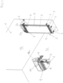
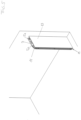
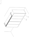
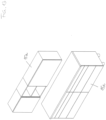
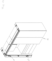
- FIGS. 1 to 8 show in a schematically indicated space a first embodiment of a guide system of a door arrangement or a furniture arrangement in a first variant of the method for assembling the furnishing arrangement.
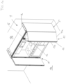
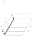
- FIGS. 9 to 11 show, starting from the Fig. 8 From the open position (parking position) shown, close the doors in steps until they are fully closed according to Fig. 11 .
- the Fig. 12 shows another embodiment with an additional lateral furniture body (wall cupboard).
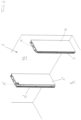
- FIGS. 13 to 16 show in similar representations as the Figures 1 to 8 a second variant of the assembly process, in which the furnishings are set up or assembled first and then the guide system or the door arrangements.
- the Figures 17 to 19 show, starting from the Fig. 16 shown open position (parking position), in steps closing the device arrangement until the completely closed position in Fig. 19 .
- Figure 1 1 generally designates a room, for example a kitchen in a building.
- This room has a floor 1a and a wall 1b.
- the embodiment of a door system for a door arrangement shown therein has a, subsequently in the Figures 8 to 10 shown furnishings 15, 15a, 15b, 18, separate support structure, which is generally designated by the reference numeral 2 and in Figure 1 already standing on the floor 1a and resting against the wall 1b is set up or mounted.
- the support structure 2 has a support surface 5 for standing on the floor 1a of the room 1 on the underside of a vertically standing, essentially rectangular plate 3 or on mounting brackets 4 mounted thereon.
- a mounting device 6 in the form of mounting brackets can also be provided on the side for mounting on the wall, which can be fastened to the wall using suitable fastening means, for example screws and dowels.
- the support surface or the mounting device for mounting on the wall 1b allow the essential technical parts of the guide system, which are described in more detail below, to be mounted securely in room 1, independent of at least one piece of furniture to be covered, as required by the Figure 1 shows.
- a column 7 in vertical alignment on which, as later the Figure 3 shows that a door (specifically a folding door) can be detachably attached via hinges 8.
- the vertical column 7, which supports the hinges 8, can be moved horizontally parallel to itself on horizontal rails 9 by means of rollers 10.
- Figure 1 the rear position of pillar 7 is shown, which corresponds to the later parking position of the door arrangement.
- the Figure 3 now shows a folding door 11 with two door leaves 11a and 11b, which are pivotally connected to one another via folding door hinges 12.
- the door leaf 11a of this folding door 11 is pivotally connected to the hinges 8 of the column 7. This connection is also detachable, and it is possible to provide pre-assembled fittings on the door leaf 11a, which can be coupled to the hinge arms of the hinges 8 in a manner known per se.
- the Figure 4 shows starting from the Figure 3 the folding door 11 pushed into the parking position.
- the door arrangement advantageously has a lateral cover plate 13 aligned parallel to the plate 3, which can be connected to the plate 3 via the angles 5 on the floor, the angles 5a on the ceiling and the mounting device 6 on the wall.
- connection options are also conceivable and possible, in particular those where the connection is not made via the floor angles forming the support surface or the mounting angles of the wall forming the mounting device to the wall. It is important that a preferably relatively narrow receiving shaft 14 is created between the two plates 3 and 13 for the door 11 in the parking position, as is the case with the Figure 5 shows.
- the Figure 6 shows a second guide system or a second door arrangement, which corresponds to the first door arrangement according to Figure 5 is essentially mirror-symmetrical and is installed at a distance from this in room 1.
- the reference symbols of this second door arrangement or the second guide system are provided with a "'", otherwise The same reference numerals are used here as for the first guide system or for the first door arrangement.
- the Figure 7 shows an autonomous, self-supporting support structure of a guide system or a door arrangement according to the basic idea of the invention.
- Furniture items can now be arranged to the side of the guide system or the door arrangement or in the space between the two door arrangements, completely independently of the autonomous guide system or the autonomous door arrangement, in order to form a furniture arrangement.
- the furniture items can be standard furniture items that do not require any special design for storing the rather complicated folding doors including the receiving shaft.
- the furniture items can have a furniture body 15 with two parallel vertical side walls, between which, for example, drawers 16' or shelves 17 can be arranged.
- the Figure 8 shows that base cabinets are provided which have a large depth, while wall-mounted upper cabinets have a smaller depth.
- the furnishings include electrical devices.
- the electrical device 18 is a stove with an oven.
- Such electrical devices usually do not have a closed wall on the side, which is not necessary due to the independent design of the door arrangement, because the door arrangement "stands" autonomously, as is the case with the Fig. 7 shows.
- FIG. 9 shows the closing of the device arrangement starting from the parking position of the Fig. 8 in individual steps:
- the folding doors 11 and 11' are pulled out of the respective receiving shaft between the plates 3, 13 on the one hand and 3', 13' on the other hand, whereby the column 7 moves forward on the guide rails 9.
- the slide 16 on the inner door leaf of the folding door is in Fig. 9 not shown, but in Fig. 10 clearly visible. It can move in the horizontal rail 14, whereby the folding door 11 unfolds, ie the two door leaves 11a and 11b swing open via the folding door hinges 12. This is in Fig. 10 clearly visible on the right.
- the Fig. 11 finally shows the fully closed position, where it is also clear that the door leaves 11a and 11a' completely cover the front sides of the side panels 3 and 3' respectively in the closed position, which enables a homogeneous, continuous appearance from the front. It is thus also possible to connect another furniture body, for example in the form of a cupboard 17, to the side without a different gap, as is the case with the Fig. 12 shows. As far as the movement of the folding door leaves 11a 11b is concerned, this can be done manually, whereby recessed door handles (not shown here) are possible, which do not protrude or can be folded in to enable the folding doors to be pushed into the corresponding receiving shaft.
- this movement is at least partially supported by energy storage devices (springs) not shown.
- springs energy storage devices
- a spring-loaded touch-latch device is provided which, when the folding door in the shaft is pushed backwards, causes it to move forwards under spring load so that it can be gripped more easily by hand. The further closing movement can then be done by hand.
- the hinges 8 or the folding door hinges 12 contain spreading springs that support a closing movement.
- FIG. 13 the preferably standardized furniture bodies in the form of a base cabinet 15a and an upper cabinet 15b are first assembled ( Fig. 13 ). Then, as the Figures 14 and 15 show - examples of the guide system with vertical plates 3 or 3' placed left and right, as shown in the Figures 14 and 15 show.
- these construction units can be delivered pre-assembled in the form of receiving shafts to enable rapid assembly. It is not necessary to connect them laterally in receiving shafts or "pockets" with the previously set up furnishings 15a, 15b, although this can certainly be done. In any case, the side “pockets” can also stand independently and be attached to the floor and/or the wall.
- Fig. 16 shows a further assembly step, where the preferably two-piece rail 14 has been mounted.
- Fig. 17 the right folding door 11 is already mounted and closed.
- the left folding door 11 ⁇ is not yet mounted on the corresponding hinges 8'. This is only possible in Fig. 18 the case, whereby the left folding door 11' is shown in the position pulled out of the shaft, but not yet closed.
- the Fig. 19 shows the fully closed position, which is essentially the Fig. 11 corresponds.
- the invention is of course not limited to the embodiments shown; for example, it is also possible to arrange the guide system or the door arrangement (pocket) only on one side and not on both sides, as shown in the figures.
- the door does not have to be a folding door. It is sufficient if the door is a normal swing door, although the width area to be covered is then smaller.
- the carriage 16 of the folding door 11 moves onto a carriage stub 16a, which is arranged at the upper end of the column 7 (see detail A in Fig. 1 ).
- This allows the carriage 16 of the folding door 11, which is parked on the carriage stub 16a, to enter the receiving shaft 14 together with the column 7.
- This is a "Park & Ride solution”.
- the rail 14' it is of course also possible for the rail 14' to be continued around a curve into the shaft of the lateral guide system.
Landscapes
- Engineering & Computer Science (AREA)
- Mechanical Engineering (AREA)
- Civil Engineering (AREA)
- Structural Engineering (AREA)
- Extensible Doors And Revolving Doors (AREA)
- Cabinets, Racks, Or The Like Of Rigid Construction (AREA)
- Support Devices For Sliding Doors (AREA)
- Combinations Of Kitchen Furniture (AREA)
- Mattresses And Other Support Structures For Chairs And Beds (AREA)
- Table Devices Or Equipment (AREA)
Description
- Die Erfindung betrifft einen Raum gemäß dem Oberbegriff nach Anspruch 1. Weiters betrifft die Erfindung auch Verfahren zum Montieren einer Einrichtungsanordnung eines solchen Raums.
- Üblicherweise werden Möbelkorpusse durch Schwenktüren oder Schiebetüren verschlossen. Der Nachteil besteht darin, dass auch im geöffneten Zustand die Türen in den Raum stehen oder bei Schiebetüre keine vollständige Öffnung erlauben. Dem entgegenzuwirken gibt es bereits den Vorschlag, die Türen zunächst zur Seite zu bewegen und dann in einen seitlichen, senkrecht zur Front des Möbelkorpus ausgerichteten Aufnahmeschacht zu schieben (beispielsweise
CH 693070 A5 - Bei der bekannten Lösung ist der Aufnahmeschacht im Möbelkorpus integriert. Es handelt sich daher um einen speziellen Möbelkorpus. Dabei gibt es zwei Varianten: in einer ersten Variante handelt es sich um eine Schwenktüre, die nach dem Herausziehen aus dem Schacht einfach um eine vertikale Schwenkachse verschwenkbar ist, um den Möbelkorpus zu verschließen. In einer zweiten Variante handelt es sich um eine Falttüre, die nach dem Herausziehen aus dem Schacht auffaltbar ist, wobei die zwei Türblätter der Falttüre über Falttürscharniere schwenkbar miteinander verbunden sind. Damit kann man eine größere Frontfläche eines Möbelkorpus abdecken. Dennoch kann die Türe platzsparend im Aufnahmeschacht geparkt werden (Parkstellung).
- Weitere Anordnungen sind aus den Schriften
WO 03/073003 A1 EP 2 345 347 A1 ,US 2,807,835 A ,DE 689 03 285 T2 undDE 28 17 161 A1 bekannt. - Aufgabe der Erfindung ist es, einen Raum mit einer Einrichtungsanordnung anzugeben, mit denen die Möglichkeiten des Verschließens und Öffnens einer Front von einem oder mehreren Einrichtungsgegenständen gegenüber den bisher bekannten Lösungen erweitert sind. Auch soll ein rasch und effizient durchführbares Montageverfahren für eine Einrichtungsanordnung angegeben werden.
- Dies wird durch einen Raum nach Anspruch 1 sowie Verfahren zum Montieren einer Einrichtungsanordnung nach Anspruch 12 oder 14 gelöst.
- Erfindungsgemäß ist bei dem Raum mit der Einrichtungsanordnung vorgesehen, dass der zumindest eine Einrichtungsgegenstand unmittelbar an der Wand des Raumes anliegend aufgestellt und/oder an der Wand befestigt ist.
- Mit dem erfindungsgemäßen Raum ist es möglich, standardisierte Möbelkorpusse, beispielsweise solche mit einem vorgegebenen Breitenraster aber auch andere Einrichtungsgegenstände, wie beispielsweise elektrische Geräte (Weißwaren) in der Schließstellung frontseitig abzudecken und dann mindestens eine Türe in einer seitlichen Parkstellung, insbesondere in einem Aufnahmeschacht, unterzubringen. Das Führungssystem bzw. die Türanordnung weist dabei eine autonome selbsttragende Struktur auf, die damit keine Spezialausbildung des Möbelkorpus selbst benötigt. Das ist besonders beim Einsatz von elektrischen Geräten als Einrichtungsgegenstand von Bedeutung, die oft seitlich keine geschlossene Fläche zum Anschließen einer Tragstruktur seitlichen Aufnahmeschachtes für die Türen aufweisen. Auch müssen sich die Möbelkorpusse nicht über die gesamte Höhe der Türe erstrecken. Es ist beispielsweise auch möglich, nur Unterschränke frontseitig abzudecken oder - wie es bei Küchen üblich ist - Unterschränke und Oberschränke, die eine gegenüber den Unterschränken reduzierte Tiefe aufweisen.
- Insgesamt sind also gemäß der Grundidee der Erfindung die abzudeckenden Einrichtungsgegenstände einerseits und die Führungssysteme bzw. Türanordnungen andererseits zum Abdecken derselben im Wesentlichen unabhängig voneinander, was nicht ausschließt, dass diese zu Sicherheitszwecken in einem abschließenden Montagevorgang auch untereinander miteinander verbunden werden. Diese Erfindung ist aber im Gegensatz zum Stand der Technik prinzipiell nicht nötig.
- Das Führungssystem bzw. die Türanordnung erlauben auch zwei unterschiedliche Montageverfahren: einmal ist es möglich, zunächst die Türanordnung bzw. das Führungssystem am Boden eines Raumes aufzustellen und/oder an der Wand eines Raumes zu montieren und anschließend seitlich daneben die Einrichtungsgegenstände (Möbelkorpusse und/oder elektrische Geräte) aufzubauen. Es ist aber auch der umgekehrte Montageablauf möglich, bei dem zunächst die Einrichtungsgegenstände, insbesondere zu einer Möbelzeile im Raum aufgestellt werden und anschließend ein Führungssystem bzw. eine Türanordnung montiert werden.
- Bei beiden Montageverfahren ist das Aufstellen der Einrichtungsgegenstände einerseits und der Türanordnung bzw. des Führungssystems andererseits im Wesentlichen unabhängig. Das kann daher auch zeitlich zu verschiedenen Zeitpunkten geschehen. Es können auch für die Einrichtungsgegenstände einerseits und für die Führungssysteme bzw. Türanordnungen andererseits verschiedene Lieferanten vorgesehen sein. Beispielsweise ist es möglich, dass ein Möbelhaus bzw. ein Küchenhersteller die Einrichtungsgegenstände liefert, während die Türanordnungen bzw. zumindest das Führungssystem für solche Türanordnungen vom Beschlägehersteller geliefert werden.
- Die Türen selbst können übrigens auch bei einer Lieferung des Führungssystems durch den Beschlägehersteller vom Möbelhaus bzw. Küchenhersteller geliefert werden, um im Design an die Einrichtungsgegenstände angepasst zu sein. Die Technik des Führungssystems kann aber jedenfalls der Beschlägehersteller unabhängig liefern. Selbstverständlich besteht aber auch die Möglichkeit, dass der Beschlägehersteller seine Technik an das Möbelhaus liefert und dieses dann die gesamte Einrichtungsanordnung in einem der beiden oben beschriebenen Montageverfahren Vorort aufstellt.
- Weitere Vorteile und Einzelheiten der Erfindung werden anhand der nachfolgenden Figurenbeschreibung näher erläutert.
- Die
Figuren 1 bis 8 zeigen in einem schematisch angedeuteten Raum ein erstes Ausführungsbeispiel eines Führungssystems einer Türanordnung bzw. einer Einrichtungsanordnung in einer ersten Variante des Verfahrens zum Montieren der Einrichtungsanordnung. - Die
Figuren 9 bis 11 zeigen, ausgehend von der inFig. 8 gezeigten Offenstellung (Parkstellung) in Schritten das Schließen der Türen bis in die vollständige Schließstellung gemäßFig. 11 . - Die
Fig. 12 zeigt ein weiteres Ausführungsbeispiel mit einem zusätzlichen seitlichen Möbelkorpus (Wandschrank). - Die
Figuren 13 bis 16 zeigen in ähnlichen Darstellungen wie dieFiguren 1 bis 8 eine zweite Variante des Montageablaufes, bei der zunächst die Einrichtungsgegenstände und anschließend das Führungssystem bzw. die Türanordnungen aufgestellt bzw. montiert werden. - Die
Figuren 17 bis 19 zeigen, ausgehend von der inFig. 16 gezeigten Offenstellung (Parkstellung), in Schritten das Schließen der Einrichtungsanordnung bis zur vollständigen Schließstellung inFig. 19 . - In
Figur 1 ist allgemein mit 1 ein Raum, beispielsweise eine Küche eines Gebäudes bezeichnet. Dieser Raum weist einen Boden 1a sowie eine Wand 1b auf. - Das dort dargestellte Ausführungsbeispiel eines Türsystems für eine Türanordnung weist eine, in weiterer Folge in den
Figuren 8 bis 10 gezeigten Einrichtungsgegenständen 15, 15a, 15b, 18, gesonderte Tragstruktur auf, die allgemein mit dem Bezugszeichen 2 bezeichnet ist und inFigur 1 bereits auf dem Boden 1a aufstehend und an der Wand 1b anliegend aufgestellt bzw. montiert ist. Dazu weist die Tragstruktur 2 an der Unterseite einer vertikal stehenden, im Wesentlichen rechteckigen Platte 3 bzw. an daran montierten Montagewinkeln 4 eine Aufstandsfläche 5 zum Aufstehen auf den Boden 1a des Raumes 1 auf. - Alternativ zu dieser Aufstandsfläche unten kann auch seitlich, zum Montieren an der Wand, eine Montageeinrichtung 6 in Form von Montagewinkeln vorgesehen sein, die über geeignete Befestigungsmittel, beispielsweise Schrauben und Dübel, in der Wand befestigbar sind.
- Im dargestellten Ausführungsbeispiel gibt es sowohl eine Aufstandsfläche 5 am Boden 1a als auch eine Montageeinrichtung 6 zum Montieren an der Wand 1b. Es reicht aber grundsätzlich aus, wenn eine dieser beiden (Aufstandsfläche, Montageeinrichtung an der Wand) vorgesehen ist.
- Jedenfalls erlauben es die Aufstandsfläche bzw. die Montageeinrichtung zum Montieren an der Wand 1b, die wesentlichen technischen Teile des Führungssystems, die im Folgenden noch näher beschrieben werden, unabhängig von mindestens einem abzudeckenden Einrichtungsgegenstand lagesicher im Raum 1 zu montieren, wie es die
Figur 1 zeigt. - Aus technischer Sicht weist das Führungssystem gemäß
Figur 1 in diesem Ausführungsbeispiel eine Säule 7 in vertikaler Ausrichtung auf, an der, wie später dieFigur 3 zeigt, eine Türe (konkret eine Falttüre) über Scharniere 8 lösbar befestigabar ist. - Der in
Figur 1 mit einem Kreis gekennzeichnete Bereich A ist links inFigur 1 im vergrößerten Maßstab dargestellt. - Die vertikale Säule 7, die die Scharniere 8 trägt, ist parallel zu sich selbst auf horizontalen Schienen 9 mittels Rollen 10 waagrecht verfahrbar.
- In
Figur 1 ist die hintere Stellung der Säule 7 gezeigt, die der späteren Parkstellung der Türanordnung entspricht. - In
Figur 2 ist die Säule 7 in die vordere Stellung verschoben, von der aus die Türanordnung, wie später gezeigt, über die Scharniere 8 in die Schließstellung bewegt werden kann. - Die
Figur 3 zeigt nun eine Falttüre 11 mit zwei Türblättern 11a und 11b, die über Falttürscharniere 12 miteinander schwenkbar verbunden sind. Von dieser Falttüre 11 ist das Türblatt 11a mit den Scharnieren 8 der Säule 7 schwenkbar verbunden. Diese Verbindung ist auch lösbar, dabei ist es möglich am Türblatt 11a vormontierte Beschlagteile vorzusehen, die mit Scharnierarmen der Scharniere 8 in an sich bekannter Weise kuppelbar sind. - Die
Figur 4 zeigt dann ausgehend von derFigur 3 die in die Parkposition eingeschobene Falttüre 11. - Wie die
Figur 5 zeigt, weist die Türanordnung vorteilhaft eine seitliche, parallel zur Platte 3 ausgerichtete Abdeckplatte 13 auf, die über die Winkel 5 am Boden, die Winkel 5a an der Decke und die Montageeinrichtung 6 an der Wand mit der Platte 3 verbunden werden kann. - Selbstverständlich sind auch andere Verbindungsmöglichkeiten denkbar und möglich, insbesondere solche, bei denen die Verbindung nicht über die, die Aufstandsfläche bildenden Bodenwinkle bzw. die Montageeinrichtung zur Wand bildenden Montagewinkel der Wand geschieht. Wichtig ist, dass zwischen den beiden Platten 3 und 13 ein vorzugsweise relativ schmaler Aufnahmeschacht 14 für die in der Parkstellung befindliche Türe 11 geschaffen wird, wie dies die
Figur 5 zeigt. - Bei dem Montageablauf in den
Figuren 1 bis 5 ist noch zu erwähnen, dass dieser hauptsächlich so gewählt wurde, dass man aus darstellungstechnischen Gründen den Innenaufbau des Führungssystems gut sieht. Es ist durchaus möglich und auch bevorzugt vorgesehen, dass die seitliche Abdeckplatte 13 schon vorher, beispielsweise im Möbelhaus oder sogar beim Beschlägehersteller, montiert wird, um einen kompletten Aufnahmeschacht 14 mit zwei seitlichen Platten 3 und 13 zu haben. Die Türe 11 kann dabei auch schon vormontiert sein, es besteht aber auch die Möglichkeit, diese an Ort und Stelle zu montieren, was aus transporttechnischen Gründen wegen des Gewichts der Türen meist zu bevorzugen sein wird. Kurzum, die Türen kann man entgegen der Darstellungen in denFiguren 1 bis 7 auch erst zum Schluss einhängen, das ist sogar auch möglich nachdem, wie es inFigur 8 gezeigt wird, die Einrichtungsgegenstände eingebaut worden sind. - Die
Figur 6 zeigt ein zweites Führungssystem bzw. eine zweite Türanordnung, die zur ersten Türanordnung gemäßFigur 5 im Wesentlichen spiegelsymmetrisch ausgebildet ist und mit Abstand von dieser im Raum 1 aufgestellt wird. Die Bezugszeichen dieser zweiten Türanordnung bzw. des zweiten Führungssystems sind mit einem "' " versehen, ansonsten werden hier die gleichen Bezugszeichen verwendet wie für das erste Führungssystem bzw. für die erste Türanordnung. - In
Figur 6 werden also zunächst zwei Führungssysteme bzw. Türanordnungen mit vorgegebenem Abstand zueinander lagerichtig im Raum 1 aufgestellt und anschließend mit einer horizontalen Schiene 14` miteinander verbunden, auf der ein oben am Türblatt 11b der Falttüre 11 bzw. der Falttüre 11' angeordneter Schlitten 16 verfahrbar sein wird. - Die
Figur 7 zeigt eine autonome selbsttragende Tragstruktur eines Führungssystems bzw. einer Türanordnung nach der Grundidee der Erfindung. Seitlich neben dem Führungssystem bzw. der Türanordnung bzw. im Raum zwischen den beiden Türanordnungen können nun völlig unabhängig vom autonomen Führungssystem bzw. der autonomen Türanordnung Einrichtungsgegenstände angeordnet werden, um eine Einrichtungsanordnung auszubilden. Dabei können die Einrichtungsgegenstände Standardeinrichtungs-gegenstände sein, die für das Lagern der doch recht komplizierten Falttüren samt Aufnahmeschacht keine besondere Ausbildung brauchen. Insbesondere können die Einrichtungsgegenstände einen Möbelkorpus 15 mit zwei parallelen vertikalen Seitenwänden aufweisen, zwischen denen beispielsweise Schubladen 16' oder Fachböden 17 angeordnet sein können. Es ist auch möglich, wie es dieFigur 8 zeigt, dass Unterschränke vorgesehen sind, die eine große Tiefe aufweisen, während an der Wand aufgehängte Oberschränke eine geringere Tiefe aufweisen. - Neben eigentlichen Möbelkorpussen ist es auch möglich, dass die Einrichtungsgegenstände elektrische Geräte umfassen. Im vorliegenden Fall ist das elektrische Gerät 18 ein Herd mit Backrohr. Solche elektrischen Geräte weisen meist seitlich keine geschlossene Wand auf, das ist durch die unabhängige Ausbildung der Türanordnung auch nicht nötig, weil eben die Türanordnung autonom "steht", wie dies die
Fig. 7 zeigt. - Die
Figuren 9 bis 11 zeigen nun das Verschließen der Einrichtungsanordnung ausgehend von der Parkstellung derFig. 8 in einzelnen Schritten:
Zunächst werden die Falttüren 11 bzw. 11` aus dem jeweiligen Aufnahmeschacht zwischen den Platten 3, 13 einerseits bzw. 3', 13' andererseits herausgezogen, wobei sich die Säule 7 auf den Führungsschienen 9 nach vorne bewegt. Der Schlitten 16 am jeweils inneren Türblatt der Falttüre ist inFig. 9 nicht dargestellt, aber inFig. 10 gut sichtbar. Er kann in der horizontalen Schiene 14 verfahren, wobei sich die Falttüre 11 auffaltet, d. h., die beiden Türblätter 11a und 11b sich über die Falttürscharniere 12 aufschwenken. Dies ist inFig. 10 rechts gut ersichtlich. - Die
Fig. 11 zeigt schließlich die vollständige Schließstellung, bei der auch ersichtlich ist, dass die Türblätter 11a und 11a' die Stirnseiten der seitlichen Platten 3 bzw. 3' in der Schließposition vollständig abdecken, was ein homogenes, durchgehendes Erscheinungsbild von vorne ermöglicht. Es ist damit auch möglich, ohne unterschiedlichem Spalt einen weiteren Möbelkorpus, beispielsweise in Form eines Schrankes 17, seitlich anzuschließen, wie dies dieFig. 12 zeigt.
Was die Bewegung der Falttürblätter 11a 11b betrifft, so kann diese von Hand erfolgen, wobei hier nicht dargestellte, eingelassene Türgriffe möglich sind, die nicht vorstehen bzw. einklappbar sind, um ein Einschieben der Falttüren in den zugehörigen Aufnahmeschacht zu ermöglichen. - Es ist auch möglich, dass diese Bewegung zumindest teilweise durch nicht dargestellte Kraftspeicher (Federn) unterstützt wird. Insbesondere ist es möglich, dass eine federbelastete Toutch-Latch-Einrichtung vorgesehen ist, die bei einem Überdrücken der im Schacht befindenden Falttüre nach hinten dieses federbelastet nach vorne bewegen lässt, um es mit der Hand besser greifen zu können. Die weitere Schließbewegung kann dann per Hand geschehen. Es ist aber auch möglich, dass in den Scharnieren 8 bzw. in den Falttürscharnieren 12 Aufspreizfedern vorhanden sind, die eine Schließbewegung unterstützen. Grundsätzlich ist es auch möglich, den Antrieb elektrisch zu unterstützen oder vollständig elektrisch angetrieben ablaufen zu lassen. All diese Antriebsvarianten sind denkbar und möglich.
- Die
Figuren 13 bis 16 zeigen nunmehr einen alternativen, umgekehrten Montageablauf, der gemäß einem weiteren bevorzugten Verfahren der Erfindung möglich ist. hier werden in einem Raum, ähnlich wie in den vorhergehenden Figuren gezeigt ist, zunächst die vorzugsweise standardisierten Möbelkorpusse in Form eines Unterschrankes 15a und eines Oberschrankes 15b aufgebaut (Fig. 13 ). Anschließend werden dann - wie dieFiguren 14 und15 zeigen - Ausführungsbeispiele des Führungssystems mit vertikalen Platten 3 bzw. 3` links und rechts aufgestellt, wie dies dieFiguren 14 und15 zeigen. - Auch hier können diese Baueinheiten in Form von Aufnahmeschächten vormontiert geliefert werden, um ein rasches Aufbauen zu ermöglichen. Dabei ist es nicht nötig, diese seitlich in Aufnahmeschächte bzw. "Pockets" mit den vorher aufgestellten Einrichtungsgegenständen 15a, 15b seitlich zu verbinden, wenngleich dies durchaus geschehen kann. Jedenfalls können die seitlichen "Pockets" auch autonom stehen und am Boden und/oder an der Wand befestigt werden.
- Die
Fig. 16 zeigt dann noch einen weiteren Aufbauschritt, an dem die vorzugsweise zweistückig ausgebildete Schiene 14 montiert worden ist. InFig. 17 ist die rechte Falttüre 11 bereits montiert und geschlossen. Die linke Falttüre 11` ist an den zugehörigen Scharnieren 8' noch nicht montiert. Das ist erst inFig. 18 der Fall, wobei hier die linke Falttüre 11' in der aus dem Schacht herausgezogenen Stellung, aber noch nicht geschlossenen Stellung, gezeigt ist. - Die
Fig. 19 zeigt wiederum die vollständige Schließstellung, die im Wesentlichen derFig. 11 entspricht. - Die Erfindung ist selbstverständlich nicht auf die dargestellten Ausführungsbeispiele beschränkt, beispielsweise ist es auch möglich, das Führungssystem bzw. die Türanordnung (Pocket) nur einseitig und nicht zweiseitig anzuordnen, wie dies in den Figuren gezeigt ist.
- Auch muss die Türe keine Falttüre sein. Es reicht aus, wenn die Türe eine normale Schwenktüre ist, wenngleich dann auch der zu überdeckende Breitenbereich geringer ist.
- In dem dargestellten Ausführungsbeispiel fährt der Schlitten 16 der Falttüre 11 auf einen Schlittenstummel 16a, der am oberen Ende der Säule 7 angeordnet ist (siehe Detail A in
Fig. 1 ). Damit kann der am Schlittenstummel 16a geparkte Schlitten 16 der Falttüre 11 zusammen mit der Säule 7 in den Aufnahmeschacht 14 einfahren. Es handelt sich dabei um eine "Park & Ride Lösung". Alternativ ist es natürlich auch möglich, dass die Schiene 14' eine Kurve herum in den Schacht des seitlichen Führungssystems fortgesetzt wird. - Selbstverständlich können auch die Einrichtungsgegenstände von den dargestellten Einrichtungsgegenständen abweichen. Es ist gerade ein Merkmal der Erfindung, dass die Gestaltung der Einrichtungsgegenstände, seien es Möbelkorpusse oder elektrische Geräte, völlig frei und unabhängig von den seitlichen Führungssystemen bzw. Türanordnungen gewählt werden kann. Spezialkorpusse, wie beim Stand der Technik, sind nicht nötig.
Claims (15)
- Raum (1) mit einem Boden (1a) und einer Wand (1b) und einer montierten Einrichtungsanordnung mit mindestens einem Einrichtungsgegenstand (15, 15a, 15b, 18) und mindestens einer seitlich neben dem mindestens einen Einrichtungsgegenstand (15, 15a, 15b, 18) angeordneten Türanordnung mit einer Tragstruktur (2) mit einem von der Wand (1b) unabhängigen Führungssystem und einer am Führungssystem verschwenkbar und vorzugsweise lösbar angebrachten Türe (11, 11'), wobei das Führungssystem eine Schließstellung, in der der mindestens eine Einrichtungsgegenstand (15, 15a, 15b, 18) frontseitig abdeckbar ist, und eine Parkstellung, in die die Türe (11, 11') mittels des Führungssystems in eine Richtung quer zu einer Front des mindestens einen Einrichtungsgegenstandes (15, 15a, 15b, 18), vorzugsweise in einen seitlichen Aufnahmeschacht des Führungssystems, bewegbar, vorzugsweise verschiebbar ist, aufweist, wobei die Tragstruktur (2) eine vom abzudeckenden Einrichtungsgegenstand (15, 15a, 15b, 18) gesonderte Tragstruktur (2) ist und das Führungssystem an der vom abzudeckenden Einrichtungsgegenstand (15, 15a, 15b, 18) gesonderten Tragstruktur (2) montiert oder ausgebildet ist, wobei die Tragstruktur (2) mindestens eine Aufstandsfläche (5), mit der die Tragstruktur (2) am Boden (1a) des Raumes aufsteht, und/oder mindestens eine Montageeinrichtung (6), durch die die Tragstruktur (2) an der Wand (16) des Raumes (1) montiert ist, aufweist, dadurch gekennzeichnet, dass der zumindest eine Einrichtungsgegenstand (15, 15a, 15b, 18) unmittelbar an der Wand (1b) des Raumes (1) anliegend aufgestellt und/oder an der Wand (1b) befestigt ist.
- Raum (1) nach Anspruch 1, dadurch gekennzeichnet, dass das Führungssystem eine Säule (7, 7') aufweist, an der die Türe (11, 11') mittels Scharnieren (8, 8') befestigt ist, und dass die Säule (7, 7') - vorzugsweise mittels Schienen (9) oder einer Scherenmechanik - quer zur Front des mindestens einen Einrichtungsgegenstandes (15, 15a, 15b, 18) und seitlich neben diesem parallel zu sich selbst an der Tragstruktur (2) verschiebbar oder bewegbar ist.
- Raum (1) nach Anspruch 1 oder 2, dadurch gekennzeichnet, dass die Tragstruktur (2) eine vertikal stehende - vorzugsweise im Wesentlichen rechteckige - Platte (3) aufweist und/oder die mindestens eine Aufstandsfläche (5) an einer unteren Stirnkante der Platte (3) ausgebildet oder angebracht ist und/oder die mindestens eine Montageeinrichtung (6) an einer hinteren Längskante der Platte (3) ausgebildet oder angebracht ist und/oder die Tragstruktur (2) eine seitliche Abdeckplatte (13, 13`) aufweist.
- Raum (1) nach Anspruch 3, dadurch gekennzeichnet, dass die seitliche Abdeckplatte (13, 13') - vorzugsweise über Abstandswinkel (5, 5a, 6) - parallel zur Platte (3, 3') angeordnet ist, wobei zwischen der Abdeckplatte (13, 13`) und der Platte (3, 3`) ein seitlicher Aufnahmeschacht für die Türe ausgebildet ist.
- Raum (1) nach einem der Ansprüche 1 bis 4, dadurch gekennzeichnet, dass das Führungssystem für die Türe (11, 11') im Inneren eines seitlichen Aufnahmeschachtes (14) angeordnet ist.
- Raum (1) nach einem der Ansprüche 1 bis 5, dadurch gekennzeichnet, dass die Tür als Falttüre (11) mit zwei Türblättern (11a, 11b) ausgebildet ist, wobei die beiden Türblätter (11a, 11b) über Falttürscharniere (12) schwenkbar miteinander verbunden sind und ein erstes Türblatt (11a) mit dem Führungssystem verbunden ist, wobei vorzugsweise vorgesehen ist, dass ein zweites Türblatt (11b) im oberen Bereich mit einem Schlitten (16) gelenkig verbunden ist, der in einer mit der Tragstruktur (2) verbindbaren Schiene (14') verfahrbar ist.
- Raum (1) nach einem der Ansprüche 1 bis 6 mit mindestens zwei nebeneinander liegenden Einrichtungsgegenständen (15, 15a, 15b, 18).
- Raum (1) nach einem der Ansprüche 1 bis 6, dadurch gekennzeichnet, dass die Einrichtungsanordnung eine zweite der Türanordnungen umfasst, wobei im montierten Zustand auf beiden Seiten seitlich neben dem zumindest einen Einrichtungsgegenstand (15, 15a, 15b, 18) jeweils eine der Türanordnungen angeordnet ist.
- Raum (1) nach Anspruch 7 und 8, dadurch gekennzeichnet, dass die Türen (11, 11') der Türanordnungen in einer Schließstellung in einer Ebene liegen und die mindestens zwei Einrichtungsgegenstände (15, 15a, 15b, 18) - vorzugsweise im Wesentlichen vollständig - abdecken und optional zusätzlich, dass die Türen der Türanordnungen in einer Schließstellung auch die jeweilige Tragstruktur (2), insbesondere den jeweiligen Aufnahmeschacht (14) der jeweiligen Tragstruktur samt seitlicher Abdeckplatte (13), frontseitig - vorzugsweise im Wesentlichen vollständig - abdecken.
- Raum (1) nach einem der Ansprüche 1 bis 6, dadurch gekennzeichnet, dass der zumindest eine Einrichtungsgegenstand (15, 15a, 15b, 18) einen Möbelkorpus (15, 15a, 15b) mit zwei parallelen, vertikalen Seitenwänden aufweist, zwischen denen vorzugsweise Schubladen (16') und/oder Fachböden (17) angeordnet sind und/oder der zumindest eine Einrichtungsgegenstand ein elektrisches Gerät (18), vorzugsweise ein Weißwaren-Gerät - wie beispielsweise ein Herd, ein Kühlschrank oder eine Geschirrspülmaschine - ist und/oder der zumindest eine Einrichtungsgegenstand (15, 15a, 15b, 18) am Boden (1a) des Raumes (1) aufsteht und/oder der zumindest eine Einrichtungsgegenstand (15, 15a, 15b, 18) an der Wand (1b) des Raumes (1) aufgehängt ist und/oder zumindest zwei, vorzugsweise mehrere Einrichtungsgegenstände (15, 15a, 15b, 18), zu einer Zeile, vorzugsweise Küchenzeile, aneinandergereiht nebeneinander stehen.
- Raum (1) nach Anspruch 7, dadurch gekennzeichnet, dass die mindestens zwei seitlich nebeneinanderliegenden Einrichtungsgegenstände (15, 15a, 15b, 18) im Wesentlichen quaderförmige Außenabmessungen, vorzugsweise mit gleicher Höhe und gleicher Tiefe aufweisen und optional zusätzlich die Breite der mindestens zwei nebeneinanderliegenden Einrichtungsgegenstände (15, 15a, 15b, 18) aus einem vorgegebenen Breitenraster, vorzugsweise mit 30cm, 45cm, 60cm und/oder 90cm Breite, ausgewählt ist.
- Verfahren zum Montieren einer Einrichtungsanordnung eines Raums (1) nach einem der Ansprüche 1 bis 11, gekennzeichnet durch folgende Schritte:- lagerichtiges Aufstellen und/oder Befestigen der Tragstruktur (2) am Boden (1a) des Raumes (1) und/oder an der Wand (1b) des Raumes (1), wobei die Tragstruktur (2) das Führungssystem zur linear bewegbaren und verschwenkbaren Lagerung der Türe (11, 11`) aufweist,- anschließendes lagerrichtiges Befestigen des mindestens einen Einrichtungsgegenstandes (15, 15a, 15b, 18) direkt seitlich neben der Tragstruktur (2) an der Wand (1b) des Raumes (1).
- Verfahren nach Anspruch 12, dadurch gekennzeichnet, dass- zwei, vorzugsweise im Wesentlichen spiegelsymmetrisch ausgebildete, Tragstrukturen (2) lagerichtig mit Abstand voneinander am Boden (1a) aufgestellt und/oder an der Wand (1b) befestigt werden, wobei jede Tragstruktur (2) mit einem Führungssystem für eine Türe (11, 11') versehen ist,- anschließend im Raum (1) zwischen den beiden Tragstrukturen (2) weitere Einrichtungsgegenstände am Boden (1a) des Raumes (1) aufgestellt und/oder an der Wand (1b) des Raumes (1) aufgehängt werden.
- Verfahren zum Montieren einer Einrichtungsanordnung eines Raums (1) nach einem der Ansprüche 1 bis 11, gekennzeichnet durch folgende Schritte:- lagerichtiges Befestigen des mindestens eineneinen Einrichtungsgegenstandes (15, 15a, 15b, 18) an der Wand (1b) des Raumes (1),- anschließendes lagerichtiges Aufstellen und/oder Befestigen mindestens einer Tragstruktur (2) am Boden (1a) des Raumes (1) und/oder an der Wand (1b) des Raumes (1), jeweils direkt neben dem zumindest einen Einrichtungsgegenstand (15, 15a, 15b, 18), wobei jede Tragstruktur (2) ein Führungssystem zur linear bewegbaren und verschwenkbaren Lagerung einer Türe (11, 11') aufweist.
- Verfahren nach einem der Ansprüche 12 bis 14, dadurch gekennzeichnet, dass die Tür (11, 11') mit dem zugehörigen Führungssystem verbunden wird:- bevor die Tragstruktur (2) des Führungssystems lagerichtig aufgestellt oder befestigt wirdund/oder die Tür (11, 11') mit dem zugehörigen Führungssystem verbunden wird:
nachdem der zumindest eine Einrichtungsgegenstand (15, 15a, 15b, 18) seitlich neben der Tragstruktur (2) aufgestellt oder befestigt worden ist.
Applications Claiming Priority (3)
| Application Number | Priority Date | Filing Date | Title |
|---|---|---|---|
| ATA50025/2017A AT519515B1 (de) | 2017-01-13 | 2017-01-13 | Einrichtungsanordnung |
| EP17825726.7A EP3568554B1 (de) | 2017-01-13 | 2017-12-22 | Einrichtungsanordnung |
| PCT/AT2017/060347 WO2018129569A1 (de) | 2017-01-13 | 2017-12-22 | Führungssystem für eine türanordnung, sowie türanordnung und einrichtungsanordnung |
Related Parent Applications (1)
| Application Number | Title | Priority Date | Filing Date |
|---|---|---|---|
| EP17825726.7A Division EP3568554B1 (de) | 2017-01-13 | 2017-12-22 | Einrichtungsanordnung |
Publications (2)
| Publication Number | Publication Date |
|---|---|
| EP4134507A1 EP4134507A1 (de) | 2023-02-15 |
| EP4134507B1 true EP4134507B1 (de) | 2024-12-04 |
Family
ID=60937474
Family Applications (2)
| Application Number | Title | Priority Date | Filing Date |
|---|---|---|---|
| EP22200039.0A Active EP4134507B1 (de) | 2017-01-13 | 2017-12-22 | Führungssystem für eine türanordnung, sowie türanordnung und einrichtungsanordnung |
| EP17825726.7A Active EP3568554B1 (de) | 2017-01-13 | 2017-12-22 | Einrichtungsanordnung |
Family Applications After (1)
| Application Number | Title | Priority Date | Filing Date |
|---|---|---|---|
| EP17825726.7A Active EP3568554B1 (de) | 2017-01-13 | 2017-12-22 | Einrichtungsanordnung |
Country Status (8)
| Country | Link |
|---|---|
| US (1) | US11585136B2 (de) |
| EP (2) | EP4134507B1 (de) |
| JP (1) | JP6997196B2 (de) |
| CN (1) | CN110325700B (de) |
| AT (1) | AT519515B1 (de) |
| ES (2) | ES2935599T3 (de) |
| TW (1) | TWI676730B (de) |
| WO (1) | WO2018129569A1 (de) |
Families Citing this family (9)
| Publication number | Priority date | Publication date | Assignee | Title |
|---|---|---|---|---|
| AT517343B1 (de) * | 2015-06-29 | 2017-01-15 | Blum Gmbh Julius | Ausstoßvorrichtung für eine Falttür oder Falt-Schiebe-Tür |
| AT519120B1 (de) * | 2017-01-13 | 2018-04-15 | Blum Gmbh Julius | Schienenanordnung für Möbelteile |
| AT519513B1 (de) * | 2017-01-13 | 2022-09-15 | Blum Gmbh Julius | Anordnung zur Führung einer Schiebetür oder Falt-Schiebetür an einer Möbelwand |
| AT519374B1 (de) * | 2017-01-13 | 2018-06-15 | Blum Gmbh Julius | Führungssystem zur Führung eines bewegbar gelagerten Möbelteiles |
| AT522261B1 (de) * | 2019-02-07 | 2020-12-15 | Blum Gmbh Julius | Anordnung zur Führung wenigstens einer bewegbaren Möbeltür |
| CN112444061B (zh) * | 2019-08-28 | 2022-03-25 | 青岛海尔电冰箱有限公司 | 可实现重心内移的对开门冰箱 |
| AT524025B1 (de) * | 2020-09-14 | 2022-02-15 | Blum Gmbh Julius | Wand für einen Möbelkorpus und Verfahren zu deren Herstellung |
| CA3211342A1 (en) * | 2021-03-09 | 2022-09-15 | Matthew Brown | Bifold door for moveable wall system |
| US12093091B1 (en) | 2024-03-11 | 2024-09-17 | TSI Touch, Inc | Protective cover apparatus for a direct-view light emitting diode (DV LED) screen and a method of protecting and maintaining the DV LED screen |
Family Cites Families (21)
| Publication number | Priority date | Publication date | Assignee | Title |
|---|---|---|---|---|
| US2807835A (en) * | 1954-06-08 | 1957-10-01 | Cornell Res Foundation Inc | Door and housing therefor |
| US3342246A (en) * | 1965-02-08 | 1967-09-19 | Stanley Works | Guide assembly for bifolding doors |
| US3456995A (en) * | 1967-04-11 | 1969-07-22 | Gen Electric | Slide-in cabinet door |
| DE2817161A1 (de) * | 1978-04-20 | 1979-10-25 | Interluebke Kg | Schrankwand |
| IT1234897B (it) * | 1988-02-19 | 1992-06-02 | Kairos Snc Bonetti Manete Mion | Dispositivo di chiusura ad ante articolate |
| JP3066140B2 (ja) * | 1991-11-11 | 2000-07-17 | 積水ハウス株式会社 | 用途別変更型ダイニングキッチンルーム |
| CH693070A5 (de) | 1998-02-02 | 2003-02-14 | Hawa Ag | Befestigungsvorrichtung einer faltbaren Tür. |
| US6056376A (en) * | 1998-10-21 | 2000-05-02 | Streater, Inc. | Display case |
| JP2002276056A (ja) * | 2001-03-16 | 2002-09-25 | Seikatsu Kachi Sozo Jutaku Kaihatsu Gijutsu Kenkyu Kumiai | パネルの組付構造 |
| DE10208472A1 (de) * | 2002-02-27 | 2003-09-25 | Bsh Bosch Siemens Hausgeraete | Haushaltsgerät |
| US7524002B2 (en) * | 2004-03-25 | 2009-04-28 | Spacesaver Corporation | Locking door system for a storage cabinet |
| CA2514702C (en) * | 2003-03-25 | 2007-12-11 | Spacesaver Corporation | Modular security cabinet system for storing firearms or the like |
| US6848758B1 (en) * | 2003-10-31 | 2005-02-01 | Chih-Cheng Yeh | Do it yourself (DIY) modular cabinet |
| US20070159037A1 (en) * | 2006-01-10 | 2007-07-12 | Knape & Vogt Manufacturing Company | Hinge bracket for a pocket door |
| ITMI20061214A1 (it) * | 2006-06-23 | 2007-12-24 | Dada S P A | Armadio o mobile similare con sportelli pieghevoli e scorrevoli a scomparsa |
| US7322661B1 (en) * | 2007-01-16 | 2008-01-29 | Karen Salvesen | Storage cabinet |
| US7896425B2 (en) * | 2009-07-15 | 2011-03-01 | Ford Global Technologies, Llc | Simultaneous movement system for a vehicle door II |
| DE102010004950A1 (de) * | 2010-01-18 | 2011-07-21 | Remis Gesellschaft für Entwicklung und Vertrieb von technischen Elementen mbH, 50829 | Kühlregal mit Türvorrichtung |
| IT1402815B1 (it) * | 2010-12-03 | 2013-09-27 | Borrtoluzzi Lab S R L | Dispositivo per l'applicazione di porte a scomparsa laterale, particolarmente per mobili |
| WO2013114730A1 (ja) * | 2012-01-31 | 2013-08-08 | スガツネ工業株式会社 | 収納式折戸装置 |
| AT516282B1 (de) * | 2014-11-26 | 2016-04-15 | Blum Gmbh Julius | Anordnung zum Aufspreizen wenigstens zweier gelenkig miteinander verbundener Türflügel |
-
2017
- 2017-01-13 AT ATA50025/2017A patent/AT519515B1/de active
- 2017-12-22 ES ES17825726T patent/ES2935599T3/es active Active
- 2017-12-22 ES ES22200039T patent/ES3013895T3/es active Active
- 2017-12-22 JP JP2019538153A patent/JP6997196B2/ja active Active
- 2017-12-22 CN CN201780087425.2A patent/CN110325700B/zh active Active
- 2017-12-22 WO PCT/AT2017/060347 patent/WO2018129569A1/de not_active Ceased
- 2017-12-22 EP EP22200039.0A patent/EP4134507B1/de active Active
- 2017-12-22 EP EP17825726.7A patent/EP3568554B1/de active Active
-
2018
- 2018-01-08 TW TW107100621A patent/TWI676730B/zh active
-
2019
- 2019-07-11 US US16/509,051 patent/US11585136B2/en active Active
Also Published As
| Publication number | Publication date |
|---|---|
| JP2020514589A (ja) | 2020-05-21 |
| CN110325700B (zh) | 2021-10-19 |
| WO2018129569A1 (de) | 2018-07-19 |
| JP6997196B2 (ja) | 2022-01-17 |
| AT519515B1 (de) | 2023-02-15 |
| AT519515A1 (de) | 2018-07-15 |
| EP3568554A1 (de) | 2019-11-20 |
| ES3013895T3 (en) | 2025-04-15 |
| EP4134507A1 (de) | 2023-02-15 |
| CN110325700A (zh) | 2019-10-11 |
| TW201829898A (zh) | 2018-08-16 |
| US20190330897A1 (en) | 2019-10-31 |
| ES2935599T3 (es) | 2023-03-08 |
| EP3568554B1 (de) | 2022-10-19 |
| TWI676730B (zh) | 2019-11-11 |
| US11585136B2 (en) | 2023-02-21 |
Similar Documents
| Publication | Publication Date | Title |
|---|---|---|
| EP4134507B1 (de) | Führungssystem für eine türanordnung, sowie türanordnung und einrichtungsanordnung | |
| EP2713816B1 (de) | Beschlag für eckschränke | |
| WO2011079400A1 (de) | Laufwerksanordnung mit einer führungsschiene für eine schiebetür | |
| WO2008135270A1 (de) | Beschlag für einen eckschrank mit einem herausziehbaren einteiligen tablar | |
| EP3558061B2 (de) | Schrank | |
| DE102018132802A1 (de) | Schiebe-Schwenkmechanik einer Ablage eines Möbels oder Haushaltsgerätes und Möbel oder Haushaltsgerät | |
| EP2429343A1 (de) | Möbelwand und möbel | |
| DE29701227U1 (de) | Schrank mit verfahrbaren Fächern | |
| DE69715279T2 (de) | Modulares korbhaltendes Gerüst für links- und rechtsöffnende Eckschränke | |
| EP2378922B1 (de) | Tragekonstruktion für einen an der wand zu montierenden möbelkorpus | |
| DE10101845C1 (de) | Schranklift | |
| EP2353439A1 (de) | Beschlag für Eckschränke | |
| DE102004016239B4 (de) | Schrank mit Schrankkorpus mit mehreren Ablagefächern | |
| DE102015007849B4 (de) | Möbel, insbesondere Schrankmöbel mit Falttüranordnung | |
| EP1776899B1 (de) | Schwenkauszug aus einem Eckschrank | |
| DE10106637C2 (de) | Schrank, insb. Hängeschrank für Küchen | |
| DE102012007306B4 (de) | Küchenschrank mit mehreren in einemSchrankfach angeordneten Platten | |
| EP2353444B1 (de) | Schrankauszug | |
| EP1989953B1 (de) | Beschlag für einen Eckschrank mit einem herausziehbaren einteiligen Tablar | |
| EP1264564B1 (de) | Möbelkorpus | |
| DE202007010284U1 (de) | Beschlag für Eckschränke | |
| DE10127311B4 (de) | Möbelkorpus | |
| DE202008017599U1 (de) | Möbel mit Expansionsraum | |
| DE1554348A1 (de) | Wandkoerper zur Abtrennung von Schrankabteilen von vorhandenen Raeumen | |
| DE1683274A1 (de) | Falttuer,z.B. fuer den Verschluss von Schraenken |
Legal Events
| Date | Code | Title | Description |
|---|---|---|---|
| PUAI | Public reference made under article 153(3) epc to a published international application that has entered the european phase |
Free format text: ORIGINAL CODE: 0009012 |
|
| STAA | Information on the status of an ep patent application or granted ep patent |
Free format text: STATUS: THE APPLICATION HAS BEEN PUBLISHED |
|
| AC | Divisional application: reference to earlier application |
Ref document number: 3568554 Country of ref document: EP Kind code of ref document: P |
|
| AK | Designated contracting states |
Kind code of ref document: A1 Designated state(s): AL AT BE BG CH CY CZ DE DK EE ES FI FR GB GR HR HU IE IS IT LI LT LU LV MC MK MT NL NO PL PT RO RS SE SI SK SM TR |
|
| P01 | Opt-out of the competence of the unified patent court (upc) registered |
Effective date: 20230523 |
|
| STAA | Information on the status of an ep patent application or granted ep patent |
Free format text: STATUS: REQUEST FOR EXAMINATION WAS MADE |
|
| 17P | Request for examination filed |
Effective date: 20230727 |
|
| RBV | Designated contracting states (corrected) |
Designated state(s): AL AT BE BG CH CY CZ DE DK EE ES FI FR GB GR HR HU IE IS IT LI LT LU LV MC MK MT NL NO PL PT RO RS SE SI SK SM TR |
|
| STAA | Information on the status of an ep patent application or granted ep patent |
Free format text: STATUS: EXAMINATION IS IN PROGRESS |
|
| 17Q | First examination report despatched |
Effective date: 20231004 |
|
| GRAP | Despatch of communication of intention to grant a patent |
Free format text: ORIGINAL CODE: EPIDOSNIGR1 |
|
| STAA | Information on the status of an ep patent application or granted ep patent |
Free format text: STATUS: GRANT OF PATENT IS INTENDED |
|
| GRAS | Grant fee paid |
Free format text: ORIGINAL CODE: EPIDOSNIGR3 |
|
| INTG | Intention to grant announced |
Effective date: 20241001 |
|
| GRAA | (expected) grant |
Free format text: ORIGINAL CODE: 0009210 |
|
| STAA | Information on the status of an ep patent application or granted ep patent |
Free format text: STATUS: THE PATENT HAS BEEN GRANTED |
|
| AC | Divisional application: reference to earlier application |
Ref document number: 3568554 Country of ref document: EP Kind code of ref document: P |
|
| AK | Designated contracting states |
Kind code of ref document: B1 Designated state(s): AL AT BE BG CH CY CZ DE DK EE ES FI FR GB GR HR HU IE IS IT LI LT LU LV MC MK MT NL NO PL PT RO RS SE SI SK SM TR |
|
| REG | Reference to a national code |
Ref country code: CH Ref legal event code: EP |
|
| REG | Reference to a national code |
Ref country code: DE Ref legal event code: R096 Ref document number: 502017016600 Country of ref document: DE |
|
| REG | Reference to a national code |
Ref country code: IE Ref legal event code: FG4D Free format text: LANGUAGE OF EP DOCUMENT: GERMAN |
|
| REG | Reference to a national code |
Ref country code: LT Ref legal event code: MG9D |
|
| REG | Reference to a national code |
Ref country code: NL Ref legal event code: MP Effective date: 20241204 |
|
| PG25 | Lapsed in a contracting state [announced via postgrant information from national office to epo] |
Ref country code: HR Free format text: LAPSE BECAUSE OF FAILURE TO SUBMIT A TRANSLATION OF THE DESCRIPTION OR TO PAY THE FEE WITHIN THE PRESCRIBED TIME-LIMIT Effective date: 20241204 |
|
| PG25 | Lapsed in a contracting state [announced via postgrant information from national office to epo] |
Ref country code: FI Free format text: LAPSE BECAUSE OF FAILURE TO SUBMIT A TRANSLATION OF THE DESCRIPTION OR TO PAY THE FEE WITHIN THE PRESCRIBED TIME-LIMIT Effective date: 20241204 |
|
| REG | Reference to a national code |
Ref country code: ES Ref legal event code: FG2A Ref document number: 3013895 Country of ref document: ES Kind code of ref document: T3 Effective date: 20250415 |
|
| PG25 | Lapsed in a contracting state [announced via postgrant information from national office to epo] |
Ref country code: BG Free format text: LAPSE BECAUSE OF FAILURE TO SUBMIT A TRANSLATION OF THE DESCRIPTION OR TO PAY THE FEE WITHIN THE PRESCRIBED TIME-LIMIT Effective date: 20241204 |
|
| PG25 | Lapsed in a contracting state [announced via postgrant information from national office to epo] |
Ref country code: NO Free format text: LAPSE BECAUSE OF FAILURE TO SUBMIT A TRANSLATION OF THE DESCRIPTION OR TO PAY THE FEE WITHIN THE PRESCRIBED TIME-LIMIT Effective date: 20250304 |
|
| PG25 | Lapsed in a contracting state [announced via postgrant information from national office to epo] |
Ref country code: LV Free format text: LAPSE BECAUSE OF FAILURE TO SUBMIT A TRANSLATION OF THE DESCRIPTION OR TO PAY THE FEE WITHIN THE PRESCRIBED TIME-LIMIT Effective date: 20241204 Ref country code: GR Free format text: LAPSE BECAUSE OF FAILURE TO SUBMIT A TRANSLATION OF THE DESCRIPTION OR TO PAY THE FEE WITHIN THE PRESCRIBED TIME-LIMIT Effective date: 20250305 |
|
| PG25 | Lapsed in a contracting state [announced via postgrant information from national office to epo] |
Ref country code: RS Free format text: LAPSE BECAUSE OF FAILURE TO SUBMIT A TRANSLATION OF THE DESCRIPTION OR TO PAY THE FEE WITHIN THE PRESCRIBED TIME-LIMIT Effective date: 20250304 |
|
| PG25 | Lapsed in a contracting state [announced via postgrant information from national office to epo] |
Ref country code: NL Free format text: LAPSE BECAUSE OF FAILURE TO SUBMIT A TRANSLATION OF THE DESCRIPTION OR TO PAY THE FEE WITHIN THE PRESCRIBED TIME-LIMIT Effective date: 20241204 |
|
| PG25 | Lapsed in a contracting state [announced via postgrant information from national office to epo] |
Ref country code: SM Free format text: LAPSE BECAUSE OF FAILURE TO SUBMIT A TRANSLATION OF THE DESCRIPTION OR TO PAY THE FEE WITHIN THE PRESCRIBED TIME-LIMIT Effective date: 20241204 |
|
| PG25 | Lapsed in a contracting state [announced via postgrant information from national office to epo] |
Ref country code: PL Free format text: LAPSE BECAUSE OF FAILURE TO SUBMIT A TRANSLATION OF THE DESCRIPTION OR TO PAY THE FEE WITHIN THE PRESCRIBED TIME-LIMIT Effective date: 20241204 |
|
| PG25 | Lapsed in a contracting state [announced via postgrant information from national office to epo] |
Ref country code: IS Free format text: LAPSE BECAUSE OF FAILURE TO SUBMIT A TRANSLATION OF THE DESCRIPTION OR TO PAY THE FEE WITHIN THE PRESCRIBED TIME-LIMIT Effective date: 20250404 |
|
| PG25 | Lapsed in a contracting state [announced via postgrant information from national office to epo] |
Ref country code: PT Free format text: LAPSE BECAUSE OF FAILURE TO SUBMIT A TRANSLATION OF THE DESCRIPTION OR TO PAY THE FEE WITHIN THE PRESCRIBED TIME-LIMIT Effective date: 20250404 |
|
| PG25 | Lapsed in a contracting state [announced via postgrant information from national office to epo] |
Ref country code: EE Free format text: LAPSE BECAUSE OF FAILURE TO SUBMIT A TRANSLATION OF THE DESCRIPTION OR TO PAY THE FEE WITHIN THE PRESCRIBED TIME-LIMIT Effective date: 20241204 |
|
| PG25 | Lapsed in a contracting state [announced via postgrant information from national office to epo] |
Ref country code: RO Free format text: LAPSE BECAUSE OF FAILURE TO SUBMIT A TRANSLATION OF THE DESCRIPTION OR TO PAY THE FEE WITHIN THE PRESCRIBED TIME-LIMIT Effective date: 20241204 |
|
| PG25 | Lapsed in a contracting state [announced via postgrant information from national office to epo] |
Ref country code: SK Free format text: LAPSE BECAUSE OF FAILURE TO SUBMIT A TRANSLATION OF THE DESCRIPTION OR TO PAY THE FEE WITHIN THE PRESCRIBED TIME-LIMIT Effective date: 20241204 |
|
| PG25 | Lapsed in a contracting state [announced via postgrant information from national office to epo] |
Ref country code: CZ Free format text: LAPSE BECAUSE OF FAILURE TO SUBMIT A TRANSLATION OF THE DESCRIPTION OR TO PAY THE FEE WITHIN THE PRESCRIBED TIME-LIMIT Effective date: 20241204 |
|
| PG25 | Lapsed in a contracting state [announced via postgrant information from national office to epo] |
Ref country code: LU Free format text: LAPSE BECAUSE OF NON-PAYMENT OF DUE FEES Effective date: 20241222 |
|
| REG | Reference to a national code |
Ref country code: DE Ref legal event code: R097 Ref document number: 502017016600 Country of ref document: DE |
|
| PG25 | Lapsed in a contracting state [announced via postgrant information from national office to epo] |
Ref country code: SE Free format text: LAPSE BECAUSE OF FAILURE TO SUBMIT A TRANSLATION OF THE DESCRIPTION OR TO PAY THE FEE WITHIN THE PRESCRIBED TIME-LIMIT Effective date: 20241204 |
|
| PG25 | Lapsed in a contracting state [announced via postgrant information from national office to epo] |
Ref country code: MC Free format text: LAPSE BECAUSE OF FAILURE TO SUBMIT A TRANSLATION OF THE DESCRIPTION OR TO PAY THE FEE WITHIN THE PRESCRIBED TIME-LIMIT Effective date: 20241204 |
|
| REG | Reference to a national code |
Ref country code: BE Ref legal event code: MM Effective date: 20241231 |
|
| PG25 | Lapsed in a contracting state [announced via postgrant information from national office to epo] |
Ref country code: DK Free format text: LAPSE BECAUSE OF FAILURE TO SUBMIT A TRANSLATION OF THE DESCRIPTION OR TO PAY THE FEE WITHIN THE PRESCRIBED TIME-LIMIT Effective date: 20241204 |
|
| PLBE | No opposition filed within time limit |
Free format text: ORIGINAL CODE: 0009261 |
|
| STAA | Information on the status of an ep patent application or granted ep patent |
Free format text: STATUS: NO OPPOSITION FILED WITHIN TIME LIMIT |
|
| REG | Reference to a national code |
Ref country code: CH Ref legal event code: L10 Free format text: ST27 STATUS EVENT CODE: U-0-0-L10-L00 (AS PROVIDED BY THE NATIONAL OFFICE) Effective date: 20251015 |
|
| PG25 | Lapsed in a contracting state [announced via postgrant information from national office to epo] |
Ref country code: BE Free format text: LAPSE BECAUSE OF NON-PAYMENT OF DUE FEES Effective date: 20241231 |
|
| PG25 | Lapsed in a contracting state [announced via postgrant information from national office to epo] |
Ref country code: IE Free format text: LAPSE BECAUSE OF NON-PAYMENT OF DUE FEES Effective date: 20241222 |
|
| 26N | No opposition filed |
Effective date: 20250905 |
|
| GBPC | Gb: european patent ceased through non-payment of renewal fee |
Effective date: 20250304 |
|
| REG | Reference to a national code |
Ref country code: CH Ref legal event code: U11 Free format text: ST27 STATUS EVENT CODE: U-0-0-U10-U11 (AS PROVIDED BY THE NATIONAL OFFICE) Effective date: 20260101 |
|
| PG25 | Lapsed in a contracting state [announced via postgrant information from national office to epo] |
Ref country code: GB Free format text: LAPSE BECAUSE OF NON-PAYMENT OF DUE FEES Effective date: 20250304 |
|
| PGFP | Annual fee paid to national office [announced via postgrant information from national office to epo] |
Ref country code: AT Payment date: 20251223 Year of fee payment: 9 |
|
| PGFP | Annual fee paid to national office [announced via postgrant information from national office to epo] |
Ref country code: IT Payment date: 20251218 Year of fee payment: 9 |
|
| PG25 | Lapsed in a contracting state [announced via postgrant information from national office to epo] |
Ref country code: FR Free format text: LAPSE BECAUSE OF NON-PAYMENT OF DUE FEES Effective date: 20250204 |
|
| PGFP | Annual fee paid to national office [announced via postgrant information from national office to epo] |
Ref country code: ES Payment date: 20260122 Year of fee payment: 9 |
|
| PGFP | Annual fee paid to national office [announced via postgrant information from national office to epo] |
Ref country code: DE Payment date: 20251229 Year of fee payment: 9 |
|
| PGFP | Annual fee paid to national office [announced via postgrant information from national office to epo] |
Ref country code: CH Payment date: 20260101 Year of fee payment: 9 |