EP4134507B1 - Système de guidage pour un ensemble porte, ensemble porte et ensemble dispositif - Google Patents
Système de guidage pour un ensemble porte, ensemble porte et ensemble dispositif Download PDFInfo
- Publication number
- EP4134507B1 EP4134507B1 EP22200039.0A EP22200039A EP4134507B1 EP 4134507 B1 EP4134507 B1 EP 4134507B1 EP 22200039 A EP22200039 A EP 22200039A EP 4134507 B1 EP4134507 B1 EP 4134507B1
- Authority
- EP
- European Patent Office
- Prior art keywords
- room
- door
- furniture
- support structure
- guide system
- Prior art date
- Legal status (The legal status is an assumption and is not a legal conclusion. Google has not performed a legal analysis and makes no representation as to the accuracy of the status listed.)
- Active
Links
Images








Classifications
-
- E—FIXED CONSTRUCTIONS
- E05—LOCKS; KEYS; WINDOW OR DOOR FITTINGS; SAFES
- E05D—HINGES OR SUSPENSION DEVICES FOR DOORS, WINDOWS OR WINGS
- E05D15/00—Suspension arrangements for wings
- E05D15/26—Suspension arrangements for wings for folding wings
- E05D15/264—Suspension arrangements for wings for folding wings for bi-fold wings
-
- E—FIXED CONSTRUCTIONS
- E05—LOCKS; KEYS; WINDOW OR DOOR FITTINGS; SAFES
- E05D—HINGES OR SUSPENSION DEVICES FOR DOORS, WINDOWS OR WINGS
- E05D15/00—Suspension arrangements for wings
- E05D15/56—Suspension arrangements for wings with successive different movements
- E05D15/58—Suspension arrangements for wings with successive different movements with both swinging and sliding movements
-
- E—FIXED CONSTRUCTIONS
- E06—DOORS, WINDOWS, SHUTTERS, OR ROLLER BLINDS IN GENERAL; LADDERS
- E06B—FIXED OR MOVABLE CLOSURES FOR OPENINGS IN BUILDINGS, VEHICLES, FENCES OR LIKE ENCLOSURES IN GENERAL, e.g. DOORS, WINDOWS, BLINDS, GATES
- E06B3/00—Window sashes, door leaves, or like elements for closing wall or like openings; Layout of fixed or moving closures, e.g. windows in wall or like openings; Features of rigidly-mounted outer frames relating to the mounting of wing frames
- E06B3/32—Arrangements of wings characterised by the manner of movement; Arrangements of movable wings in openings; Features of wings or frames relating solely to the manner of movement of the wing
- E06B3/48—Wings connected at their edges, e.g. foldable wings
- E06B3/481—Wings foldable in a zig-zag manner or bi-fold wings
- E06B3/482—Wings foldable in a zig-zag manner or bi-fold wings specially adapted for furniture
-
- E—FIXED CONSTRUCTIONS
- E06—DOORS, WINDOWS, SHUTTERS, OR ROLLER BLINDS IN GENERAL; LADDERS
- E06B—FIXED OR MOVABLE CLOSURES FOR OPENINGS IN BUILDINGS, VEHICLES, FENCES OR LIKE ENCLOSURES IN GENERAL, e.g. DOORS, WINDOWS, BLINDS, GATES
- E06B3/00—Window sashes, door leaves, or like elements for closing wall or like openings; Layout of fixed or moving closures, e.g. windows in wall or like openings; Features of rigidly-mounted outer frames relating to the mounting of wing frames
- E06B3/32—Arrangements of wings characterised by the manner of movement; Arrangements of movable wings in openings; Features of wings or frames relating solely to the manner of movement of the wing
- E06B3/50—Arrangements of wings characterised by the manner of movement; Arrangements of movable wings in openings; Features of wings or frames relating solely to the manner of movement of the wing with more than one kind of movement
- E06B3/5045—Arrangements of wings characterised by the manner of movement; Arrangements of movable wings in openings; Features of wings or frames relating solely to the manner of movement of the wing with more than one kind of movement specially adapted for furniture
-
- E—FIXED CONSTRUCTIONS
- E05—LOCKS; KEYS; WINDOW OR DOOR FITTINGS; SAFES
- E05Y—INDEXING SCHEME ASSOCIATED WITH SUBCLASSES E05D AND E05F, RELATING TO CONSTRUCTION ELEMENTS, ELECTRIC CONTROL, POWER SUPPLY, POWER SIGNAL OR TRANSMISSION, USER INTERFACES, MOUNTING OR COUPLING, DETAILS, ACCESSORIES, AUXILIARY OPERATIONS NOT OTHERWISE PROVIDED FOR, APPLICATION THEREOF
- E05Y2900/00—Application of doors, windows, wings or fittings thereof
- E05Y2900/20—Application of doors, windows, wings or fittings thereof for furniture, e.g. cabinets
- E05Y2900/212—Doors disappearing in pockets in the furniture body
Definitions
- the invention relates to a room according to the preamble of claim 1. Furthermore, the invention also relates to methods for assembling a furnishing arrangement of such a room.
- Furniture bodies are usually closed with hinged doors or sliding doors.
- the disadvantage is that even when opened, the doors protrude into the room or, in the case of sliding doors, do not allow complete opening.
- To counteract this there is already a suggestion to first move the doors to the side and then slide them into a lateral slot aligned perpendicular to the front of the furniture body (for example CH 693070 A5 ).
- the receiving shaft is integrated into the furniture body. It is therefore a special furniture body.
- the first variant is a pivoting door that can be easily pivoted around a vertical pivot axis after being pulled out of the shaft to close the furniture body.
- the second variant is a folding door that can be folded out after being pulled out of the shaft, with the two door leaves of the folding door being pivotally connected to one another via folding door hinges. This means that a larger front surface of a furniture body can be covered. Nevertheless, the door can be parked in the receiving shaft to save space (parking position).
- the object of the invention is to provide a room with a furnishing arrangement with which the possibilities of closing and opening a front of one or more pieces of furniture are expanded compared to the previously known solutions.
- a quick and efficient assembly method for a furnishing arrangement is also to be provided.
- the at least one piece of furniture is placed directly against the wall of the room and/or is attached to the wall.
- the space according to the invention it is possible to cover standardized furniture bodies, for example those with a specified width grid, but also other furnishings, such as electrical devices (white goods) in the closed position at the front and then to accommodate at least one door in a lateral parking position, in particular in a receiving shaft.
- the guide system or the door arrangement has an autonomous, self-supporting structure, which therefore does not require any special design of the furniture body itself. This is particularly important when using electrical Appliances are important as a piece of furniture, which often do not have a closed surface on the side for connecting a supporting structure or a side slot for the doors.
- the furniture bodies do not have to extend over the entire height of the door. It is also possible, for example, to only cover the front of the base units or - as is common in kitchens - base units and wall units that have a reduced depth compared to the base units.
- the furnishings to be covered on the one hand and the guide systems or door arrangements for covering them on the other hand are essentially independent of each other, which does not rule out the possibility that they are also connected to each other in a final assembly process for safety purposes.
- this invention is not necessary in principle.
- the guide system or door arrangement also allows two different assembly methods: firstly, it is possible to set up the door arrangement or guide system on the floor of a room and/or to mount it on the wall of a room and then to set up the furnishings (furniture bodies and/or electrical devices) next to it.
- the reverse assembly process is also possible, in which the furnishings, particularly in a row of furniture, are first set up in the room and then a guide system or door arrangement is mounted.
- the installation of the furnishings on the one hand and the door arrangement or guide system on the other are essentially independent. This can therefore also take place at different times.
- Different suppliers can also be provided for the furnishings on the one hand and the guide systems or door arrangements on the other. For example, it is possible for a furniture store or a kitchen manufacturer to supply the furnishings, while the door arrangements or at least the guide system for such door arrangements are supplied by the fittings manufacturer.
- the doors themselves can also be supplied by the furniture store or kitchen manufacturer if the guide system is supplied by the fittings manufacturer, so that the design can be adapted to the furnishings.
- the fittings manufacturer can supply the technology of the guide system independently.
- the fittings manufacturer it is also possible for the fittings manufacturer to supply its technology to the furniture store, which then sets up the entire furnishing arrangement on site using one of the two assembly methods described above.
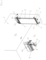
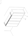
- FIGS. 1 to 8 show in a schematically indicated space a first embodiment of a guide system of a door arrangement or a furniture arrangement in a first variant of the method for assembling the furnishing arrangement.
- FIGS. 9 to 11 show, starting from the Fig. 8 From the open position (parking position) shown, close the doors in steps until they are fully closed according to Fig. 11 .
- the Fig. 12 shows another embodiment with an additional lateral furniture body (wall cupboard).
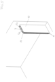
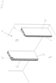
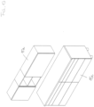
- FIGS. 13 to 16 show in similar representations as the Figures 1 to 8 a second variant of the assembly process, in which the furnishings are set up or assembled first and then the guide system or the door arrangements.
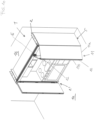
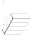
- the Figures 17 to 19 show, starting from the Fig. 16 shown open position (parking position), in steps closing the device arrangement until the completely closed position in Fig. 19 .
- Figure 1 1 generally designates a room, for example a kitchen in a building.
- This room has a floor 1a and a wall 1b.
- the embodiment of a door system for a door arrangement shown therein has a, subsequently in the Figures 8 to 10 shown furnishings 15, 15a, 15b, 18, separate support structure, which is generally designated by the reference numeral 2 and in Figure 1 already standing on the floor 1a and resting against the wall 1b is set up or mounted.
- the support structure 2 has a support surface 5 for standing on the floor 1a of the room 1 on the underside of a vertically standing, essentially rectangular plate 3 or on mounting brackets 4 mounted thereon.
- a mounting device 6 in the form of mounting brackets can also be provided on the side for mounting on the wall, which can be fastened to the wall using suitable fastening means, for example screws and dowels.
- the support surface or the mounting device for mounting on the wall 1b allow the essential technical parts of the guide system, which are described in more detail below, to be mounted securely in room 1, independent of at least one piece of furniture to be covered, as required by the Figure 1 shows.
- a column 7 in vertical alignment on which, as later the Figure 3 shows that a door (specifically a folding door) can be detachably attached via hinges 8.
- the vertical column 7, which supports the hinges 8, can be moved horizontally parallel to itself on horizontal rails 9 by means of rollers 10.
- Figure 1 the rear position of pillar 7 is shown, which corresponds to the later parking position of the door arrangement.
- the Figure 3 now shows a folding door 11 with two door leaves 11a and 11b, which are pivotally connected to one another via folding door hinges 12.
- the door leaf 11a of this folding door 11 is pivotally connected to the hinges 8 of the column 7. This connection is also detachable, and it is possible to provide pre-assembled fittings on the door leaf 11a, which can be coupled to the hinge arms of the hinges 8 in a manner known per se.
- the Figure 4 shows starting from the Figure 3 the folding door 11 pushed into the parking position.
- the door arrangement advantageously has a lateral cover plate 13 aligned parallel to the plate 3, which can be connected to the plate 3 via the angles 5 on the floor, the angles 5a on the ceiling and the mounting device 6 on the wall.
- connection options are also conceivable and possible, in particular those where the connection is not made via the floor angles forming the support surface or the mounting angles of the wall forming the mounting device to the wall. It is important that a preferably relatively narrow receiving shaft 14 is created between the two plates 3 and 13 for the door 11 in the parking position, as is the case with the Figure 5 shows.
- the Figure 6 shows a second guide system or a second door arrangement, which corresponds to the first door arrangement according to Figure 5 is essentially mirror-symmetrical and is installed at a distance from this in room 1.
- the reference symbols of this second door arrangement or the second guide system are provided with a "'", otherwise The same reference numerals are used here as for the first guide system or for the first door arrangement.
- the Figure 7 shows an autonomous, self-supporting support structure of a guide system or a door arrangement according to the basic idea of the invention.
- Furniture items can now be arranged to the side of the guide system or the door arrangement or in the space between the two door arrangements, completely independently of the autonomous guide system or the autonomous door arrangement, in order to form a furniture arrangement.
- the furniture items can be standard furniture items that do not require any special design for storing the rather complicated folding doors including the receiving shaft.
- the furniture items can have a furniture body 15 with two parallel vertical side walls, between which, for example, drawers 16' or shelves 17 can be arranged.
- the Figure 8 shows that base cabinets are provided which have a large depth, while wall-mounted upper cabinets have a smaller depth.
- the furnishings include electrical devices.
- the electrical device 18 is a stove with an oven.
- Such electrical devices usually do not have a closed wall on the side, which is not necessary due to the independent design of the door arrangement, because the door arrangement "stands" autonomously, as is the case with the Fig. 7 shows.
- FIG. 9 shows the closing of the device arrangement starting from the parking position of the Fig. 8 in individual steps:
- the folding doors 11 and 11' are pulled out of the respective receiving shaft between the plates 3, 13 on the one hand and 3', 13' on the other hand, whereby the column 7 moves forward on the guide rails 9.
- the slide 16 on the inner door leaf of the folding door is in Fig. 9 not shown, but in Fig. 10 clearly visible. It can move in the horizontal rail 14, whereby the folding door 11 unfolds, ie the two door leaves 11a and 11b swing open via the folding door hinges 12. This is in Fig. 10 clearly visible on the right.
- the Fig. 11 finally shows the fully closed position, where it is also clear that the door leaves 11a and 11a' completely cover the front sides of the side panels 3 and 3' respectively in the closed position, which enables a homogeneous, continuous appearance from the front. It is thus also possible to connect another furniture body, for example in the form of a cupboard 17, to the side without a different gap, as is the case with the Fig. 12 shows. As far as the movement of the folding door leaves 11a 11b is concerned, this can be done manually, whereby recessed door handles (not shown here) are possible, which do not protrude or can be folded in to enable the folding doors to be pushed into the corresponding receiving shaft.
- this movement is at least partially supported by energy storage devices (springs) not shown.
- springs energy storage devices
- a spring-loaded touch-latch device is provided which, when the folding door in the shaft is pushed backwards, causes it to move forwards under spring load so that it can be gripped more easily by hand. The further closing movement can then be done by hand.
- the hinges 8 or the folding door hinges 12 contain spreading springs that support a closing movement.
- FIG. 13 the preferably standardized furniture bodies in the form of a base cabinet 15a and an upper cabinet 15b are first assembled ( Fig. 13 ). Then, as the Figures 14 and 15 show - examples of the guide system with vertical plates 3 or 3' placed left and right, as shown in the Figures 14 and 15 show.
- these construction units can be delivered pre-assembled in the form of receiving shafts to enable rapid assembly. It is not necessary to connect them laterally in receiving shafts or "pockets" with the previously set up furnishings 15a, 15b, although this can certainly be done. In any case, the side “pockets” can also stand independently and be attached to the floor and/or the wall.
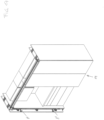
- Fig. 16 shows a further assembly step, where the preferably two-piece rail 14 has been mounted.
- Fig. 17 the right folding door 11 is already mounted and closed.
- the left folding door 11 ⁇ is not yet mounted on the corresponding hinges 8'. This is only possible in Fig. 18 the case, whereby the left folding door 11' is shown in the position pulled out of the shaft, but not yet closed.
- the Fig. 19 shows the fully closed position, which is essentially the Fig. 11 corresponds.
- the invention is of course not limited to the embodiments shown; for example, it is also possible to arrange the guide system or the door arrangement (pocket) only on one side and not on both sides, as shown in the figures.
- the door does not have to be a folding door. It is sufficient if the door is a normal swing door, although the width area to be covered is then smaller.
- the carriage 16 of the folding door 11 moves onto a carriage stub 16a, which is arranged at the upper end of the column 7 (see detail A in Fig. 1 ).
- This allows the carriage 16 of the folding door 11, which is parked on the carriage stub 16a, to enter the receiving shaft 14 together with the column 7.
- This is a "Park & Ride solution”.
- the rail 14' it is of course also possible for the rail 14' to be continued around a curve into the shaft of the lateral guide system.
Landscapes
- Engineering & Computer Science (AREA)
- Mechanical Engineering (AREA)
- Civil Engineering (AREA)
- Structural Engineering (AREA)
- Extensible Doors And Revolving Doors (AREA)
- Cabinets, Racks, Or The Like Of Rigid Construction (AREA)
- Support Devices For Sliding Doors (AREA)
- Combinations Of Kitchen Furniture (AREA)
- Mattresses And Other Support Structures For Chairs And Beds (AREA)
- Table Devices Or Equipment (AREA)
Claims (15)
- Pièce (1) avec un sol (1a) et un mur (1b) et un ensemble d'ameublement monté avec au moins un élément d'ameublement (15, 15a, 15b, 18) et au moins un ensemble de portes disposé latéralement à côté de l'au moins un élément d'ameublement (15, 15a, 15b, 18) avec une structure porteuse (2) avec un système de guidage indépendant du mur (1b) et une porte (11, 11') installée de manière à pouvoir pivoter sur le système de guidage et de préférence de manière amovible, dans laquelle le système de guidage présente une position de fermeture, dans laquelle l'au moins un élément d'ameublement (15, 15a, 15b, 18) peut être recouvert côté façade, et une position de rangement, dans laquelle la porte (11, 11') peut être déplacée, en particulier coulissée, au moyen du système de guidage dans une direction de manière transversale à une façade de l'au moins un élément d'ameublement (15, 15a, 15b, 18), de préférence dans un compartiment de réception latéral du système de guidage, dans laquelle la structure porteuse (2) est une structure porteuse (2) séparée de l'élément d'ameublement (15, 15a, 15b, 18) à recouvrir et le système de guidage est monté ou réalisé sur la structure porteuse (2) séparée de l'élément d'ameublement (15, 15a, 15b, 18) à recouvrir, dans laquelle la structure porteuse (2) présente au moins une surface d'appui (5), par laquelle la structure porteuse (2) se tient debout sur le sol (1a) de la pièce, et/ou au moins un dispositif de montage (6), par lequel la structure porteuse (2) est montée sur le mur (16) de la pièce (1), caractérisée en ce que l'au moins un élément d'ameublement (15, 15a, 15b, 18) est posé directement contre le mur (1b) de la pièce (1) et/ou est fixé au mur (1b).
- Pièce (1) selon la revendication 1, caractérisée en ce que le système de guidage présente une colonne (7, 7'), sur laquelle la porte (11, 11') est fixée au moyen de charnières (8, 8'), et que la colonne (7, 7') peut être coulissée ou déplacée - de préférence au moyen de rails (9) ou d'un mécanisme à ciseaux - de manière transversale par rapport à la façade de l'au moins un élément d'ameublement (15, 15a, 15b, 18) et latéralement à côté de celui-ci de manière parallèle à luimême sur la structure porteuse (2).
- Pièce (1) selon la revendication 1 ou 2, caractérisée en ce que la structure porteuse (2) présente un panneau (3) situé verticalement - de préférence sensiblement rectangulaire - et/ou l'au moins une surface d'appui (5) est réalisée ou installée sur une arête frontale inférieure du panneau (3) et/ou l'au moins un dispositif de montage (6) est réalisé ou installé sur une arête longitudinale arrière du panneau (3) et/ou la structure porteuse (2) présente un panneau de recouvrement latéral (13, 13').
- Pièce (1) selon la revendication 3, caractérisée en ce que le panneau de recouvrement latéral (13, 13') est disposé de manière parallèle au panneau (3, 3') - de préférence sur des angles d'espacement (5, 5a, 6) -, dans laquelle un compartiment de réception latéral pour la porte est réalisé entre le panneau de recouvrement (13, 13') et le panneau (3, 3').
- Pièce (1) selon l'une quelconque des revendications 1 à 4, caractérisée en ce que le système de guidage pour la porte (11, 11') est disposé à l'intérieur d'un compartiment de réception latérale (14).
- Pièce (1) selon l'une quelconque des revendications 1 à 5, caractérisée en ce que la porte est réalisée en tant que porte pliante (11) avec deux vantaux de porte (11a, 11b), dans laquelle les deux vantaux de porte (11a, 11b) sont reliés l'un à l'autre de manière à pouvoir pivoter par l'intermédiaire de charnières de porte pliante (12), et un premier vantail de prote (11a) est relié au système de guidage, dans laquelle il est prévu de préférence que un deuxième vantail de porte (11b) est relié de manière articulée dans la zone supérieure à un chariot (16), qui peut être déplacé dans un rail (14') pouvant être relié à la structure porteuse (2).
- Pièce (1) selon l'une quelconque des revendications 1 à 6 avec au moins deux meubles (15, 15a, 15b, 18) situés côte à côte.
- Pièce (1) selon l'une quelconque des revendications 1 à 6, caractérisée en ce que l'ensemble d'ameublement comprend un deuxième des ensembles de portes, dans laquelle respectivement un des ensembles de portes est disposé dans l'état monté sur deux côtés latéralement à côté de l'au moins un élément d'ameublement (15, 15a, 15b, 18).
- Pièce (1) selon la revendication 7 et 8, caractérisée en ce que les portes (11, 11') des ensembles de portes se situent dans un plan dans une position de fermeture et recouvrent les au moins deux meubles (15, 15a, 15b, 18) - de préférence sensiblement totalement -, et en supplément de manière optionnelle que les portes des ensembles de portes recouvrent - de préférence sensiblement totalement - dans une position de fermeture également la structure porteuse (2) respective, en particulier le compartiment de réception (14) respectif de la structure porteuse respective y compris le panneau de recouvrement latéral (13), côté frontal.
- Pièce (1) selon l'une quelconque des revendications 1 à 6, caractérisée en ce que l'au moins un élément d'ameublement (15, 15a, 15b, 18) présente un corps de meuble (15, 15a, 15b) avec deux parois latérales parallèles verticales, entre lesquelles respectivement des tiroirs (16') et/ou des étagères (17) sont disposés et/ou l'au moins un élément d'ameublement est un appareil électrique (18), de préférence un appareil électroménager - comme une cuisinière, un réfrigérateur ou un lave-vaisselle - et/ou l'au moins un élément d'ameublement (15, 15a, 15b, 18) se tient debout sur le sol (1a) de la pièce (1) et/ou l'au moins un élément d'ameublement (15, 15a, 15b, 18) est suspendu sur le mur (1b) de la pièce (1) et/ou au moins deux, de préférence plusieurs éléments d'ameublement (15, 15a, 15b, 18) sont côte à côte de manière alignée par rapport à un linéaire, de préférence un linéaire de cuisine.
- Pièce (1) selon la revendication 7, caractérisée en ce que les au moins deux éléments d'ameublement (15, 15a, 15b, 18) situés latéralement côte à côte présentent sensiblement des dimensions carrées, de préférence avec une hauteur identique et une profondeur identique et en supplément de manière optionnelle la largeur des au moins deux éléments d'ameublement (15, 15a, 15b, 18) situés côte à côte est choisie parmi une grille de largeurs spécifiée, de préférence avec une largeur de 30 cm, de 45 cm, de 60 cm et/ou de 90 cm.
- Procédé de montage d'un ensemble d'ameublement d'une pièce (1) selon l'une quelconque des revendications 1 à 11, caractérisé par des étapes suivantes :- le placement et/ou la fixation en bonne et due forme de la structure porteuse (2) sur le sol (1a) de la pièce (1) et/ou sur le mur (1b) de la pièce (1), dans lequel la structure porteuse (2) présente le système de guidage destiné à déplacer et à faire pivoter linéairement la porte (11, 11'),- ensuite la fixation en bonne et due forme de l'au moins un élément d'ameublement (15, 15a, 15b, 18) directement latéralement à côté de la structure porteuse (2) sur le mur (1b) de la pièce (1).
- Procédé selon la revendication 12, caractérisé en ce que- deux structures porteuses (2) réalisées sensiblement de manière symétrique en miroir sont placées en bonne et due forme à distance l'une de l'autre sur le sol (1a) et/ou sont fixées sur le mur (1b), dans lequel chaque structure porteuse (2) est pourvue d'un système de guidage pour une porte (11, 11'),- puis d'autres éléments d'ameublement sont placés sur le sol (1a) de la pièce (1) et/ou sont suspendus sur le mur (1b) de la pièce (1) dans la pièce (1) entre les deux structures porteuses (2).
- Procédé de montage d'un ensemble d'ameublement d'une pièce (1) selon l'une quelconque des revendications 1 à 11, caractérisé par des étapes suivantes :- la fixation en bonne et due forme de l'au moins un élément d'ameublement (15, 15a, 15b, 18) sur le mur (1b) de la pièce (1),- puis le placement et/ou la fixation en bonne et due forme d'au moins une structure porteuse (2) sur le sol (1a) de la pièce (1) et/ou sur le mur (1b) de la pièce (1), respectivement directement à côté de l'au moins un élément d'ameublement (15, 15a, 15b, 18), dans lequel chaque structure porteuse (2) présente un système de guidage destiné à monter de manière mobile et pivotante linéairement une porte (11, 11').
- Procédé selon l'une quelconque des revendications 12 à 14, caractérisé en ce que la porte (11, 11') est reliée au système de guidage associé :- avant que la structure porteuse (2) du système de guidage ne soit placée ou fixée en bonne et due formeet/ou la porte (11, 11') est reliée au système de guidage associé :
après que l'au moins un élément d'ameublement (15, 15a, 15b, 18) a été placé ou fixé latéralement à côté de la structure porteuse (2).
Applications Claiming Priority (3)
| Application Number | Priority Date | Filing Date | Title |
|---|---|---|---|
| ATA50025/2017A AT519515B1 (de) | 2017-01-13 | 2017-01-13 | Einrichtungsanordnung |
| EP17825726.7A EP3568554B1 (fr) | 2017-01-13 | 2017-12-22 | Mobilier |
| PCT/AT2017/060347 WO2018129569A1 (fr) | 2017-01-13 | 2017-12-22 | Système de guidage conçu pour un ensemble porte, ensemble porte et ensemble équipement |
Related Parent Applications (1)
| Application Number | Title | Priority Date | Filing Date |
|---|---|---|---|
| EP17825726.7A Division EP3568554B1 (fr) | 2017-01-13 | 2017-12-22 | Mobilier |
Publications (2)
| Publication Number | Publication Date |
|---|---|
| EP4134507A1 EP4134507A1 (fr) | 2023-02-15 |
| EP4134507B1 true EP4134507B1 (fr) | 2024-12-04 |
Family
ID=60937474
Family Applications (2)
| Application Number | Title | Priority Date | Filing Date |
|---|---|---|---|
| EP22200039.0A Active EP4134507B1 (fr) | 2017-01-13 | 2017-12-22 | Système de guidage pour un ensemble porte, ensemble porte et ensemble dispositif |
| EP17825726.7A Active EP3568554B1 (fr) | 2017-01-13 | 2017-12-22 | Mobilier |
Family Applications After (1)
| Application Number | Title | Priority Date | Filing Date |
|---|---|---|---|
| EP17825726.7A Active EP3568554B1 (fr) | 2017-01-13 | 2017-12-22 | Mobilier |
Country Status (8)
| Country | Link |
|---|---|
| US (1) | US11585136B2 (fr) |
| EP (2) | EP4134507B1 (fr) |
| JP (1) | JP6997196B2 (fr) |
| CN (1) | CN110325700B (fr) |
| AT (1) | AT519515B1 (fr) |
| ES (2) | ES2935599T3 (fr) |
| TW (1) | TWI676730B (fr) |
| WO (1) | WO2018129569A1 (fr) |
Families Citing this family (9)
| Publication number | Priority date | Publication date | Assignee | Title |
|---|---|---|---|---|
| AT517343B1 (de) * | 2015-06-29 | 2017-01-15 | Blum Gmbh Julius | Ausstoßvorrichtung für eine Falttür oder Falt-Schiebe-Tür |
| AT519120B1 (de) * | 2017-01-13 | 2018-04-15 | Blum Gmbh Julius | Schienenanordnung für Möbelteile |
| AT519513B1 (de) * | 2017-01-13 | 2022-09-15 | Blum Gmbh Julius | Anordnung zur Führung einer Schiebetür oder Falt-Schiebetür an einer Möbelwand |
| AT519374B1 (de) * | 2017-01-13 | 2018-06-15 | Blum Gmbh Julius | Führungssystem zur Führung eines bewegbar gelagerten Möbelteiles |
| AT522261B1 (de) * | 2019-02-07 | 2020-12-15 | Blum Gmbh Julius | Anordnung zur Führung wenigstens einer bewegbaren Möbeltür |
| CN112444061B (zh) * | 2019-08-28 | 2022-03-25 | 青岛海尔电冰箱有限公司 | 可实现重心内移的对开门冰箱 |
| AT524025B1 (de) * | 2020-09-14 | 2022-02-15 | Blum Gmbh Julius | Wand für einen Möbelkorpus und Verfahren zu deren Herstellung |
| CA3211342A1 (fr) * | 2021-03-09 | 2022-09-15 | Matthew Brown | Porte pliante pour systeme de paroi mobile |
| US12093091B1 (en) | 2024-03-11 | 2024-09-17 | TSI Touch, Inc | Protective cover apparatus for a direct-view light emitting diode (DV LED) screen and a method of protecting and maintaining the DV LED screen |
Family Cites Families (21)
| Publication number | Priority date | Publication date | Assignee | Title |
|---|---|---|---|---|
| US2807835A (en) * | 1954-06-08 | 1957-10-01 | Cornell Res Foundation Inc | Door and housing therefor |
| US3342246A (en) * | 1965-02-08 | 1967-09-19 | Stanley Works | Guide assembly for bifolding doors |
| US3456995A (en) * | 1967-04-11 | 1969-07-22 | Gen Electric | Slide-in cabinet door |
| DE2817161A1 (de) * | 1978-04-20 | 1979-10-25 | Interluebke Kg | Schrankwand |
| IT1234897B (it) * | 1988-02-19 | 1992-06-02 | Kairos Snc Bonetti Manete Mion | Dispositivo di chiusura ad ante articolate |
| JP3066140B2 (ja) * | 1991-11-11 | 2000-07-17 | 積水ハウス株式会社 | 用途別変更型ダイニングキッチンルーム |
| CH693070A5 (de) | 1998-02-02 | 2003-02-14 | Hawa Ag | Befestigungsvorrichtung einer faltbaren Tür. |
| US6056376A (en) * | 1998-10-21 | 2000-05-02 | Streater, Inc. | Display case |
| JP2002276056A (ja) * | 2001-03-16 | 2002-09-25 | Seikatsu Kachi Sozo Jutaku Kaihatsu Gijutsu Kenkyu Kumiai | パネルの組付構造 |
| DE10208472A1 (de) * | 2002-02-27 | 2003-09-25 | Bsh Bosch Siemens Hausgeraete | Haushaltsgerät |
| US7524002B2 (en) * | 2004-03-25 | 2009-04-28 | Spacesaver Corporation | Locking door system for a storage cabinet |
| CA2514702C (fr) * | 2003-03-25 | 2007-12-11 | Spacesaver Corporation | Systeme de coffre de securite modulaire permettant de ranger des armes a feu ou analogues |
| US6848758B1 (en) * | 2003-10-31 | 2005-02-01 | Chih-Cheng Yeh | Do it yourself (DIY) modular cabinet |
| US20070159037A1 (en) * | 2006-01-10 | 2007-07-12 | Knape & Vogt Manufacturing Company | Hinge bracket for a pocket door |
| ITMI20061214A1 (it) * | 2006-06-23 | 2007-12-24 | Dada S P A | Armadio o mobile similare con sportelli pieghevoli e scorrevoli a scomparsa |
| US7322661B1 (en) * | 2007-01-16 | 2008-01-29 | Karen Salvesen | Storage cabinet |
| US7896425B2 (en) * | 2009-07-15 | 2011-03-01 | Ford Global Technologies, Llc | Simultaneous movement system for a vehicle door II |
| DE102010004950A1 (de) * | 2010-01-18 | 2011-07-21 | Remis Gesellschaft für Entwicklung und Vertrieb von technischen Elementen mbH, 50829 | Kühlregal mit Türvorrichtung |
| IT1402815B1 (it) * | 2010-12-03 | 2013-09-27 | Borrtoluzzi Lab S R L | Dispositivo per l'applicazione di porte a scomparsa laterale, particolarmente per mobili |
| WO2013114730A1 (fr) * | 2012-01-31 | 2013-08-08 | スガツネ工業株式会社 | Dispositif de porte pliante escamotée |
| AT516282B1 (de) * | 2014-11-26 | 2016-04-15 | Blum Gmbh Julius | Anordnung zum Aufspreizen wenigstens zweier gelenkig miteinander verbundener Türflügel |
-
2017
- 2017-01-13 AT ATA50025/2017A patent/AT519515B1/de active
- 2017-12-22 ES ES17825726T patent/ES2935599T3/es active Active
- 2017-12-22 ES ES22200039T patent/ES3013895T3/es active Active
- 2017-12-22 JP JP2019538153A patent/JP6997196B2/ja active Active
- 2017-12-22 CN CN201780087425.2A patent/CN110325700B/zh active Active
- 2017-12-22 WO PCT/AT2017/060347 patent/WO2018129569A1/fr not_active Ceased
- 2017-12-22 EP EP22200039.0A patent/EP4134507B1/fr active Active
- 2017-12-22 EP EP17825726.7A patent/EP3568554B1/fr active Active
-
2018
- 2018-01-08 TW TW107100621A patent/TWI676730B/zh active
-
2019
- 2019-07-11 US US16/509,051 patent/US11585136B2/en active Active
Also Published As
| Publication number | Publication date |
|---|---|
| JP2020514589A (ja) | 2020-05-21 |
| CN110325700B (zh) | 2021-10-19 |
| WO2018129569A1 (fr) | 2018-07-19 |
| JP6997196B2 (ja) | 2022-01-17 |
| AT519515B1 (de) | 2023-02-15 |
| AT519515A1 (de) | 2018-07-15 |
| EP3568554A1 (fr) | 2019-11-20 |
| ES3013895T3 (en) | 2025-04-15 |
| EP4134507A1 (fr) | 2023-02-15 |
| CN110325700A (zh) | 2019-10-11 |
| TW201829898A (zh) | 2018-08-16 |
| US20190330897A1 (en) | 2019-10-31 |
| ES2935599T3 (es) | 2023-03-08 |
| EP3568554B1 (fr) | 2022-10-19 |
| TWI676730B (zh) | 2019-11-11 |
| US11585136B2 (en) | 2023-02-21 |
Similar Documents
| Publication | Publication Date | Title |
|---|---|---|
| EP4134507B1 (fr) | Système de guidage pour un ensemble porte, ensemble porte et ensemble dispositif | |
| EP2713816B1 (fr) | Ferrure de placard d'angle | |
| WO2011079400A1 (fr) | Agencement de mécanisme de roulement comprenant un rail de guidage pour porte coulissante | |
| WO2008135270A1 (fr) | Ferrure pour armoire d'angle comprenant un plateau monobloc extractible | |
| EP3558061B2 (fr) | Armoire | |
| DE102018132802A1 (de) | Schiebe-Schwenkmechanik einer Ablage eines Möbels oder Haushaltsgerätes und Möbel oder Haushaltsgerät | |
| EP2429343A1 (fr) | Paroi de meuble et meuble | |
| DE29701227U1 (de) | Schrank mit verfahrbaren Fächern | |
| DE69715279T2 (de) | Modulares korbhaltendes Gerüst für links- und rechtsöffnende Eckschränke | |
| EP2378922B1 (fr) | Structure de support pour un corps de meuble à monter au mur | |
| DE10101845C1 (de) | Schranklift | |
| EP2353439A1 (fr) | Armature pour une armoire angulaire | |
| DE102004016239B4 (de) | Schrank mit Schrankkorpus mit mehreren Ablagefächern | |
| DE102015007849B4 (de) | Möbel, insbesondere Schrankmöbel mit Falttüranordnung | |
| EP1776899B1 (fr) | Tiroir pivotant d'une armoire d'angle | |
| DE10106637C2 (de) | Schrank, insb. Hängeschrank für Küchen | |
| DE102012007306B4 (de) | Küchenschrank mit mehreren in einemSchrankfach angeordneten Platten | |
| EP2353444B1 (fr) | Tiroir d'armoire | |
| EP1989953B1 (fr) | Armature pour une armoire angulaire dotée d'une étagère en une partie amovible | |
| EP1264564B1 (fr) | Corps de meuble | |
| DE202007010284U1 (de) | Beschlag für Eckschränke | |
| DE10127311B4 (de) | Möbelkorpus | |
| DE202008017599U1 (de) | Möbel mit Expansionsraum | |
| DE1554348A1 (de) | Wandkoerper zur Abtrennung von Schrankabteilen von vorhandenen Raeumen | |
| DE1683274A1 (de) | Falttuer,z.B. fuer den Verschluss von Schraenken |
Legal Events
| Date | Code | Title | Description |
|---|---|---|---|
| PUAI | Public reference made under article 153(3) epc to a published international application that has entered the european phase |
Free format text: ORIGINAL CODE: 0009012 |
|
| STAA | Information on the status of an ep patent application or granted ep patent |
Free format text: STATUS: THE APPLICATION HAS BEEN PUBLISHED |
|
| AC | Divisional application: reference to earlier application |
Ref document number: 3568554 Country of ref document: EP Kind code of ref document: P |
|
| AK | Designated contracting states |
Kind code of ref document: A1 Designated state(s): AL AT BE BG CH CY CZ DE DK EE ES FI FR GB GR HR HU IE IS IT LI LT LU LV MC MK MT NL NO PL PT RO RS SE SI SK SM TR |
|
| P01 | Opt-out of the competence of the unified patent court (upc) registered |
Effective date: 20230523 |
|
| STAA | Information on the status of an ep patent application or granted ep patent |
Free format text: STATUS: REQUEST FOR EXAMINATION WAS MADE |
|
| 17P | Request for examination filed |
Effective date: 20230727 |
|
| RBV | Designated contracting states (corrected) |
Designated state(s): AL AT BE BG CH CY CZ DE DK EE ES FI FR GB GR HR HU IE IS IT LI LT LU LV MC MK MT NL NO PL PT RO RS SE SI SK SM TR |
|
| STAA | Information on the status of an ep patent application or granted ep patent |
Free format text: STATUS: EXAMINATION IS IN PROGRESS |
|
| 17Q | First examination report despatched |
Effective date: 20231004 |
|
| GRAP | Despatch of communication of intention to grant a patent |
Free format text: ORIGINAL CODE: EPIDOSNIGR1 |
|
| STAA | Information on the status of an ep patent application or granted ep patent |
Free format text: STATUS: GRANT OF PATENT IS INTENDED |
|
| GRAS | Grant fee paid |
Free format text: ORIGINAL CODE: EPIDOSNIGR3 |
|
| INTG | Intention to grant announced |
Effective date: 20241001 |
|
| GRAA | (expected) grant |
Free format text: ORIGINAL CODE: 0009210 |
|
| STAA | Information on the status of an ep patent application or granted ep patent |
Free format text: STATUS: THE PATENT HAS BEEN GRANTED |
|
| AC | Divisional application: reference to earlier application |
Ref document number: 3568554 Country of ref document: EP Kind code of ref document: P |
|
| AK | Designated contracting states |
Kind code of ref document: B1 Designated state(s): AL AT BE BG CH CY CZ DE DK EE ES FI FR GB GR HR HU IE IS IT LI LT LU LV MC MK MT NL NO PL PT RO RS SE SI SK SM TR |
|
| REG | Reference to a national code |
Ref country code: CH Ref legal event code: EP |
|
| REG | Reference to a national code |
Ref country code: DE Ref legal event code: R096 Ref document number: 502017016600 Country of ref document: DE |
|
| REG | Reference to a national code |
Ref country code: IE Ref legal event code: FG4D Free format text: LANGUAGE OF EP DOCUMENT: GERMAN |
|
| REG | Reference to a national code |
Ref country code: LT Ref legal event code: MG9D |
|
| REG | Reference to a national code |
Ref country code: NL Ref legal event code: MP Effective date: 20241204 |
|
| PG25 | Lapsed in a contracting state [announced via postgrant information from national office to epo] |
Ref country code: HR Free format text: LAPSE BECAUSE OF FAILURE TO SUBMIT A TRANSLATION OF THE DESCRIPTION OR TO PAY THE FEE WITHIN THE PRESCRIBED TIME-LIMIT Effective date: 20241204 |
|
| PG25 | Lapsed in a contracting state [announced via postgrant information from national office to epo] |
Ref country code: FI Free format text: LAPSE BECAUSE OF FAILURE TO SUBMIT A TRANSLATION OF THE DESCRIPTION OR TO PAY THE FEE WITHIN THE PRESCRIBED TIME-LIMIT Effective date: 20241204 |
|
| REG | Reference to a national code |
Ref country code: ES Ref legal event code: FG2A Ref document number: 3013895 Country of ref document: ES Kind code of ref document: T3 Effective date: 20250415 |
|
| PG25 | Lapsed in a contracting state [announced via postgrant information from national office to epo] |
Ref country code: BG Free format text: LAPSE BECAUSE OF FAILURE TO SUBMIT A TRANSLATION OF THE DESCRIPTION OR TO PAY THE FEE WITHIN THE PRESCRIBED TIME-LIMIT Effective date: 20241204 |
|
| PG25 | Lapsed in a contracting state [announced via postgrant information from national office to epo] |
Ref country code: NO Free format text: LAPSE BECAUSE OF FAILURE TO SUBMIT A TRANSLATION OF THE DESCRIPTION OR TO PAY THE FEE WITHIN THE PRESCRIBED TIME-LIMIT Effective date: 20250304 |
|
| PG25 | Lapsed in a contracting state [announced via postgrant information from national office to epo] |
Ref country code: LV Free format text: LAPSE BECAUSE OF FAILURE TO SUBMIT A TRANSLATION OF THE DESCRIPTION OR TO PAY THE FEE WITHIN THE PRESCRIBED TIME-LIMIT Effective date: 20241204 Ref country code: GR Free format text: LAPSE BECAUSE OF FAILURE TO SUBMIT A TRANSLATION OF THE DESCRIPTION OR TO PAY THE FEE WITHIN THE PRESCRIBED TIME-LIMIT Effective date: 20250305 |
|
| PG25 | Lapsed in a contracting state [announced via postgrant information from national office to epo] |
Ref country code: RS Free format text: LAPSE BECAUSE OF FAILURE TO SUBMIT A TRANSLATION OF THE DESCRIPTION OR TO PAY THE FEE WITHIN THE PRESCRIBED TIME-LIMIT Effective date: 20250304 |
|
| PG25 | Lapsed in a contracting state [announced via postgrant information from national office to epo] |
Ref country code: NL Free format text: LAPSE BECAUSE OF FAILURE TO SUBMIT A TRANSLATION OF THE DESCRIPTION OR TO PAY THE FEE WITHIN THE PRESCRIBED TIME-LIMIT Effective date: 20241204 |
|
| PG25 | Lapsed in a contracting state [announced via postgrant information from national office to epo] |
Ref country code: SM Free format text: LAPSE BECAUSE OF FAILURE TO SUBMIT A TRANSLATION OF THE DESCRIPTION OR TO PAY THE FEE WITHIN THE PRESCRIBED TIME-LIMIT Effective date: 20241204 |
|
| PG25 | Lapsed in a contracting state [announced via postgrant information from national office to epo] |
Ref country code: PL Free format text: LAPSE BECAUSE OF FAILURE TO SUBMIT A TRANSLATION OF THE DESCRIPTION OR TO PAY THE FEE WITHIN THE PRESCRIBED TIME-LIMIT Effective date: 20241204 |
|
| PG25 | Lapsed in a contracting state [announced via postgrant information from national office to epo] |
Ref country code: IS Free format text: LAPSE BECAUSE OF FAILURE TO SUBMIT A TRANSLATION OF THE DESCRIPTION OR TO PAY THE FEE WITHIN THE PRESCRIBED TIME-LIMIT Effective date: 20250404 |
|
| PG25 | Lapsed in a contracting state [announced via postgrant information from national office to epo] |
Ref country code: PT Free format text: LAPSE BECAUSE OF FAILURE TO SUBMIT A TRANSLATION OF THE DESCRIPTION OR TO PAY THE FEE WITHIN THE PRESCRIBED TIME-LIMIT Effective date: 20250404 |
|
| PG25 | Lapsed in a contracting state [announced via postgrant information from national office to epo] |
Ref country code: EE Free format text: LAPSE BECAUSE OF FAILURE TO SUBMIT A TRANSLATION OF THE DESCRIPTION OR TO PAY THE FEE WITHIN THE PRESCRIBED TIME-LIMIT Effective date: 20241204 |
|
| PG25 | Lapsed in a contracting state [announced via postgrant information from national office to epo] |
Ref country code: RO Free format text: LAPSE BECAUSE OF FAILURE TO SUBMIT A TRANSLATION OF THE DESCRIPTION OR TO PAY THE FEE WITHIN THE PRESCRIBED TIME-LIMIT Effective date: 20241204 |
|
| PG25 | Lapsed in a contracting state [announced via postgrant information from national office to epo] |
Ref country code: SK Free format text: LAPSE BECAUSE OF FAILURE TO SUBMIT A TRANSLATION OF THE DESCRIPTION OR TO PAY THE FEE WITHIN THE PRESCRIBED TIME-LIMIT Effective date: 20241204 |
|
| PG25 | Lapsed in a contracting state [announced via postgrant information from national office to epo] |
Ref country code: CZ Free format text: LAPSE BECAUSE OF FAILURE TO SUBMIT A TRANSLATION OF THE DESCRIPTION OR TO PAY THE FEE WITHIN THE PRESCRIBED TIME-LIMIT Effective date: 20241204 |
|
| PG25 | Lapsed in a contracting state [announced via postgrant information from national office to epo] |
Ref country code: LU Free format text: LAPSE BECAUSE OF NON-PAYMENT OF DUE FEES Effective date: 20241222 |
|
| REG | Reference to a national code |
Ref country code: DE Ref legal event code: R097 Ref document number: 502017016600 Country of ref document: DE |
|
| PG25 | Lapsed in a contracting state [announced via postgrant information from national office to epo] |
Ref country code: SE Free format text: LAPSE BECAUSE OF FAILURE TO SUBMIT A TRANSLATION OF THE DESCRIPTION OR TO PAY THE FEE WITHIN THE PRESCRIBED TIME-LIMIT Effective date: 20241204 |
|
| PG25 | Lapsed in a contracting state [announced via postgrant information from national office to epo] |
Ref country code: MC Free format text: LAPSE BECAUSE OF FAILURE TO SUBMIT A TRANSLATION OF THE DESCRIPTION OR TO PAY THE FEE WITHIN THE PRESCRIBED TIME-LIMIT Effective date: 20241204 |
|
| REG | Reference to a national code |
Ref country code: BE Ref legal event code: MM Effective date: 20241231 |
|
| PG25 | Lapsed in a contracting state [announced via postgrant information from national office to epo] |
Ref country code: DK Free format text: LAPSE BECAUSE OF FAILURE TO SUBMIT A TRANSLATION OF THE DESCRIPTION OR TO PAY THE FEE WITHIN THE PRESCRIBED TIME-LIMIT Effective date: 20241204 |
|
| PLBE | No opposition filed within time limit |
Free format text: ORIGINAL CODE: 0009261 |
|
| STAA | Information on the status of an ep patent application or granted ep patent |
Free format text: STATUS: NO OPPOSITION FILED WITHIN TIME LIMIT |
|
| REG | Reference to a national code |
Ref country code: CH Ref legal event code: L10 Free format text: ST27 STATUS EVENT CODE: U-0-0-L10-L00 (AS PROVIDED BY THE NATIONAL OFFICE) Effective date: 20251015 |
|
| PG25 | Lapsed in a contracting state [announced via postgrant information from national office to epo] |
Ref country code: BE Free format text: LAPSE BECAUSE OF NON-PAYMENT OF DUE FEES Effective date: 20241231 |
|
| PG25 | Lapsed in a contracting state [announced via postgrant information from national office to epo] |
Ref country code: IE Free format text: LAPSE BECAUSE OF NON-PAYMENT OF DUE FEES Effective date: 20241222 |
|
| 26N | No opposition filed |
Effective date: 20250905 |
|
| GBPC | Gb: european patent ceased through non-payment of renewal fee |
Effective date: 20250304 |
|
| REG | Reference to a national code |
Ref country code: CH Ref legal event code: U11 Free format text: ST27 STATUS EVENT CODE: U-0-0-U10-U11 (AS PROVIDED BY THE NATIONAL OFFICE) Effective date: 20260101 |
|
| PG25 | Lapsed in a contracting state [announced via postgrant information from national office to epo] |
Ref country code: GB Free format text: LAPSE BECAUSE OF NON-PAYMENT OF DUE FEES Effective date: 20250304 |
|
| PGFP | Annual fee paid to national office [announced via postgrant information from national office to epo] |
Ref country code: AT Payment date: 20251223 Year of fee payment: 9 |
|
| PGFP | Annual fee paid to national office [announced via postgrant information from national office to epo] |
Ref country code: IT Payment date: 20251218 Year of fee payment: 9 |
|
| PG25 | Lapsed in a contracting state [announced via postgrant information from national office to epo] |
Ref country code: FR Free format text: LAPSE BECAUSE OF NON-PAYMENT OF DUE FEES Effective date: 20250204 |
|
| PGFP | Annual fee paid to national office [announced via postgrant information from national office to epo] |
Ref country code: ES Payment date: 20260122 Year of fee payment: 9 |
|
| PGFP | Annual fee paid to national office [announced via postgrant information from national office to epo] |
Ref country code: DE Payment date: 20251229 Year of fee payment: 9 |
|
| PGFP | Annual fee paid to national office [announced via postgrant information from national office to epo] |
Ref country code: CH Payment date: 20260101 Year of fee payment: 9 |