EP4134580A1 - Groupe fonctionnel de soupape pour un système guidant du liquide et système guidant du liquide doté d'un tel appareil électroménager et d'un réservoir de liquide - Google Patents
Groupe fonctionnel de soupape pour un système guidant du liquide et système guidant du liquide doté d'un tel appareil électroménager et d'un réservoir de liquide Download PDFInfo
- Publication number
- EP4134580A1 EP4134580A1 EP22184404.6A EP22184404A EP4134580A1 EP 4134580 A1 EP4134580 A1 EP 4134580A1 EP 22184404 A EP22184404 A EP 22184404A EP 4134580 A1 EP4134580 A1 EP 4134580A1
- Authority
- EP
- European Patent Office
- Prior art keywords
- socket
- coupling
- seal
- valve function
- function group
- Prior art date
- Legal status (The legal status is an assumption and is not a legal conclusion. Google has not performed a legal analysis and makes no representation as to the accuracy of the status listed.)
- Granted
Links
Images

Classifications
-
- F—MECHANICAL ENGINEERING; LIGHTING; HEATING; WEAPONS; BLASTING
- F16—ENGINEERING ELEMENTS AND UNITS; GENERAL MEASURES FOR PRODUCING AND MAINTAINING EFFECTIVE FUNCTIONING OF MACHINES OR INSTALLATIONS; THERMAL INSULATION IN GENERAL
- F16L—PIPES; JOINTS OR FITTINGS FOR PIPES; SUPPORTS FOR PIPES, CABLES OR PROTECTIVE TUBING; MEANS FOR THERMAL INSULATION IN GENERAL
- F16L55/00—Devices or appurtenances for use in, or in connection with, pipes or pipe systems
- F16L55/10—Means for stopping flow in pipes or hoses
- F16L55/11—Plugs
-
- F—MECHANICAL ENGINEERING; LIGHTING; HEATING; WEAPONS; BLASTING
- F16—ENGINEERING ELEMENTS AND UNITS; GENERAL MEASURES FOR PRODUCING AND MAINTAINING EFFECTIVE FUNCTIONING OF MACHINES OR INSTALLATIONS; THERMAL INSULATION IN GENERAL
- F16K—VALVES; TAPS; COCKS; ACTUATING-FLOATS; DEVICES FOR VENTING OR AERATING
- F16K15/00—Check valves
- F16K15/14—Check valves with flexible valve members
- F16K15/144—Check valves with flexible valve members the closure elements being fixed along all or a part of their periphery
- F16K15/147—Check valves with flexible valve members the closure elements being fixed along all or a part of their periphery the closure elements having specially formed slits or being of an elongated easily collapsible form
- F16K15/1471—Check valves with flexible valve members the closure elements being fixed along all or a part of their periphery the closure elements having specially formed slits or being of an elongated easily collapsible form slits arranged along multiple axes
-
- F—MECHANICAL ENGINEERING; LIGHTING; HEATING; WEAPONS; BLASTING
- F16—ENGINEERING ELEMENTS AND UNITS; GENERAL MEASURES FOR PRODUCING AND MAINTAINING EFFECTIVE FUNCTIONING OF MACHINES OR INSTALLATIONS; THERMAL INSULATION IN GENERAL
- F16L—PIPES; JOINTS OR FITTINGS FOR PIPES; SUPPORTS FOR PIPES, CABLES OR PROTECTIVE TUBING; MEANS FOR THERMAL INSULATION IN GENERAL
- F16L27/00—Adjustable joints; Joints allowing movement
- F16L27/08—Adjustable joints; Joints allowing movement allowing adjustment or movement only about the axis of one pipe
- F16L27/087—Joints with radial fluid passages
-
- F—MECHANICAL ENGINEERING; LIGHTING; HEATING; WEAPONS; BLASTING
- F16—ENGINEERING ELEMENTS AND UNITS; GENERAL MEASURES FOR PRODUCING AND MAINTAINING EFFECTIVE FUNCTIONING OF MACHINES OR INSTALLATIONS; THERMAL INSULATION IN GENERAL
- F16L—PIPES; JOINTS OR FITTINGS FOR PIPES; SUPPORTS FOR PIPES, CABLES OR PROTECTIVE TUBING; MEANS FOR THERMAL INSULATION IN GENERAL
- F16L27/00—Adjustable joints; Joints allowing movement
- F16L27/12—Adjustable joints; Joints allowing movement allowing substantial longitudinal adjustment or movement
-
- D—TEXTILES; PAPER
- D06—TREATMENT OF TEXTILES OR THE LIKE; LAUNDERING; FLEXIBLE MATERIALS NOT OTHERWISE PROVIDED FOR
- D06F—LAUNDERING, DRYING, IRONING, PRESSING OR FOLDING TEXTILE ARTICLES
- D06F39/00—Details of washing machines not specific to a single type of machines covered by groups D06F9/00 - D06F27/00
- D06F39/02—Devices for adding soap or other washing agents
- D06F39/022—Devices for adding soap or other washing agents in a liquid state
Definitions
- the invention relates to a valve function group for a liquid-carrying system and a liquid-carrying system with a household appliance and a liquid tank.
- valve function groups for liquid-carrying systems and liquid-carrying systems with a household appliance and a liquid tank are already known from the prior art in a large number of embodiments.
- these valve functional groups always serve to seal off the liquid tank when the liquid tank is not fluidly connected to the household appliance.
- the valve function groups fulfill the purpose of being able to connect the liquid tank to the household appliance in a flow-conducting manner.
- the invention therefore addresses the problem of improving a valve functional group for a liquid-carrying system and a liquid-carrying system with a household appliance and a liquid tank.
- valve function group with the features of claim 1, according to which the valve function group comprises a coupling socket for the flow-conducting connection of the valve function group to the liquid tank and a coupling socket inserted in a plug-in position into a socket receptacle of the coupling socket in a flow-conducting manner for the flow-conducting connection of the valve function group with the household appliance , wherein the coupling socket has a closed position blocking a flow path that connects the liquid tank to the socket receptacle in a flow-conducting manner and an open position that opens the flow path and the flow path can be blocked in its closed position and opened in its open position only by means of elastic deformation of the socket seal .
- the household appliance can be a washing machine for textiles, for example.
- other types of washing machines and generally other water-bearing household appliances are also conceivable.
- the liquid-carrying system can also have a commercial device, ie a device for professional use, instead of the household appliance.
- valve function group for a liquid-carrying system with a household appliance and a liquid tank is improved. Due to the design of the valve function group according to the invention, it is possible on the one hand to significantly reduce the structural complexity of the valve function group. On the one hand, the production of the valve functional group is correspondingly simplified. On the other hand, this also reduces the number of components, so that logistics and warehousing are also simplified. All in all, the valve function group according to the invention can be produced much more cost-effectively and with reduced weight. Furthermore, the valve function group according to the invention can also be realized with a smaller number of different materials. Accordingly, the recyclability of the valve functional group is significantly improved.
- valve functional group according to the invention can be freely selected in terms of type, mode of operation, material and dimensioning within wide, suitable limits. See, for example, the relevant statements in the introduction to the description.
- valve function group according to the invention provides that the socket seal is designed in such a way that the socket seal can be transferred from its closed position to its open position by means of a mechanical force exerted by the coupling piece on the socket seal when it is transferred to its inserted position, preferably only by means of the aforementioned force .
- the valve function group according to the invention can be implemented in a manner that is simple in terms of design and manufacture and in a robust manner. This applies in particular to the preferred embodiment of this development.
- the bush seal has an actuating projection, the actuating projection being designed in such a way that the bush seal can be elastically deformed when the coupling piece is transferred into its plugged-in position by means of the actuating projection, preferably only by means of the actuating projection .
- the force exerted by the coupling piece on the bushing seal during the transfer of the coupling piece into its inserted position can be increased.
- the actuating projection can protrude far enough out of the remainder of the bush seal.
- the actuating projection it is possible by means of the actuating projection to allow the coupling piece to act in a targeted manner on the bush seal, so that the force acting on the bush seal is very defined.
- the type, function, material and dimensioning of the bush seal can be freely selected within wide, suitable limits.
- a further advantageous development of the valve function group according to the invention provides that the bush seal is designed as a squeeze element with at least one slot. Squeeze elements are available on the market in a large number of designs and can therefore be used for a wide variety of applications.
- valve function group provides that the bush seal is designed in such a way that the bush seal in its closed position engages with a sealing projection in a flow path opening of the coupling bush in a sealing manner, preferably that the sealing projection when the bush seal is transferred into its open position at least partially the flow path opening can be lifted in a flow-conducting manner.
- the sealing effect of the bush seal is significantly improved.
- the preferred embodiment of this development has the further advantage that the bush seal can be transferred into its open position without additional structural adjustments to the bush seal, for example without slits that can be opened in a flow-conducting manner by means of negative pressure.
- valve function group provides that the bush seal has a peripheral connecting section or at least two diametrically opposite connecting sections at its edge region, the bush seal being connected to the coupling bush by means of the at least one connecting section in a force-transmitting manner.
- the bush seal can be connected to the coupling bush in a manner that is particularly simple in terms of design and production technology.
- the bush seal is designed in such a way that the bush seal can be transferred from its closed position to its open position and/or from its open position to its closed position by means of a vacuum applied to the bush seal, preferably only by means of a vacuum is. In this way it is possible that the bush seal can only be transferred from its closed position to its open position when it is actually required.
- the insertion of the coupling piece into the plug-in receptacle of the coupling socket for example plugging the liquid tank with the coupling socket onto the coupling socket of the household appliance, only serves to prepare the actual flow-conducting connection between the liquid tank on the one hand and the household appliance on the other side. First by applying the negative pressure, the bush seal is transferred from its closed position to its open position and the flow path between the liquid tank and the socket receptacle is thus opened.
- valve functional group provides that two circumferential connection piece seals are adapted to the connection piece receptacle and are arranged on the coupling connection piece in such a way that a negative pressure can be built up in the connection point receptacle by means of the coupling connection piece in its inserted position such that this negative pressure can be used to Bush seal in the open position can be converted.
- a negative pressure can be built up in the connection point receptacle by means of the coupling connection piece in its inserted position such that this negative pressure can be used to Bush seal in the open position can be converted.
- valve function group provides that two peripheral connector seals for sealing the connector receptacle are arranged on the coupling connector in an area between the two connector seals when the connector connector is in its inserted position and two peripheral ventilation grooves are arranged on the coupling sleeve, the connector seals and the ventilation grooves are designed and arranged to correspond to one another in such a way that a negative pressure acting between the coupling socket and the coupling socket can be reduced when the coupling socket is transferred into a non-inserted position of the coupling socket, in which the coupling socket is not inserted into the socket receptacle.
- valve function group additionally comprises a transport socket, the transport socket being adapted to the socket receptacle of the coupling socket with the socket seal arranged thereon in such a way that the socket seal can be secured in its closed position when the transport socket is inserted into the socket receptacle .
- the bush seal can be secured in its closed position in a robust manner. This is particularly important when transporting the liquid tank.
- the liquid-carrying system according to the invention can be freely selected within wide, suitable limits in terms of type, function, material and dimensioning. See, for example, the relevant statements in the introduction to the description. Provision is advantageously made for the coupling socket to be designed as an integral part of the household appliance and the coupling socket to be designed as an integral part of the liquid tank. In this way, the complexity of the liquid-carrying system according to the invention is significantly reduced. The handling for a user of the liquid-carrying system according to the invention is correspondingly simplified. The ease of use for the user is improved.
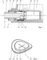
- the liquid-carrying system 2 has a household appliance 4 designed as a washing machine for textiles, a liquid tank 6 designed as a detergent cartridge with detergent (not shown) and a valve function group 8 for the optional flow-conducting connection of the liquid tank 6 with or flow-conducting separation of the liquid tank 6 from the household appliance 4.
- a household appliance 4 designed as a washing machine for textiles
- a liquid tank 6 designed as a detergent cartridge with detergent (not shown)
- a valve function group 8 for the optional flow-conducting connection of the liquid tank 6 with or flow-conducting separation of the liquid tank 6 from the household appliance 4.
- the valve function group 8 for the liquid-carrying system 2 includes a coupling socket 10 for the flow-conducting connection of the valve function group 8 to the liquid tank 6 and in one in the 1 and 3 shown insertion position in a nozzle receptacle 12 of the coupling socket 10 flow-conductingly inserted coupling socket 14 for flow-conducting connection of the valve function group 8 with the household appliance 4, wherein the coupling socket 10 is between a flow path 16 that fluidly connects the liquid tank 6 with the socket receptacle 12 and a closed position blocking the flow path 16 opening opening position back and forth transferable bushing seal 18 and the flow path 16 only by means of an elastic deformation of the bushing seal 18 in its in the Figures 1 to 4 shown closed position can be blocked and opened in the open position, not shown.
- the coupling socket 14 is designed as an integral part of the household appliance 4 and the coupling socket 10 is designed as an integral part of the liquid tank 6 .
- Both the coupling socket 10 and the coupling piece 14 are each made of a thermoplastic here.
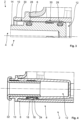
- the bush seal 18 is designed here as a squeeze element made of an elastomer with two slots 20 arranged crosswise. See the 2 , in which the sleeve seal 18 is shown in its closed position. Furthermore, the bush seal 18 is designed in such a way that the bush seal 18 in its closed position and in its open position engages with a sealing projection 22 in a flow path opening 24 of the coupling bush 10 in a sealing manner. In addition, the bush seal 18 has a peripheral connecting section 26 on its edge region, the bush seal 18 being connected to the coupling bush 10 in a force-transmitting manner by means of the connecting section 26 .
- a large number of connection techniques are available to the person skilled in the art for this purpose. Purely as an example, only multi-component injection molding or latching by means of a fastening ring or the like should be mentioned here.
- the bushing seal 18 is designed in such a way that the bushing seal 18 can be moved from its closed position to its
- Opening position can be transferred.
- tabs of the bushing seal 18 formed by the two cross-shaped slots 20 are released by means of the applied negative pressure from the in the 2 raised position shown, so that the flow path 16, namely the flow path opening 24 of the coupling sleeve 10 is open.
- the aforementioned tabs return to those from the 2 visible position back, so that the bush seal 18 is again in its closed position. The flow path 16 is again blocked.
- two circumferential socket seals 28 are adapted to the socket receptacle 12 and arranged on the coupling socket 14 in such a way that a negative pressure can be built up by means of the coupling socket 14 in its inserted position in the socket receptacle 12 in such a way that this negative pressure causes the bush seal 18 can be converted into the open position.
- two circumferential ventilation grooves 30 are arranged in an area between the two socket seals 28 when the coupling socket 14 is in its inserted position on the coupling socket 10, with the socket seals 28 and the ventilation grooves 30 corresponding to one another in this way are constructed and arranged such that a negative pressure acting between the coupling socket 10 and the coupling socket 14 can be reduced during the transfer of the coupling socket 14 into a non-inserted position of the coupling socket 14, in which the coupling socket 14 is not inserted into the socket receptacle 12.
- valve function group 8 of the present exemplary embodiment also includes a transport socket 32 made of thermoplastic, with the transport socket 32 being adapted to the socket receptacle 12 of the coupling socket 10 with the socket seal 18 arranged thereon in such a way that the socket seal 18 when the transport socket 32 is inserted into the socket socket 12 can be secured in its closed position. See the 4 , in which the transport socket 32 is shown in an inserted position of the transport socket 32, in which the transport socket 32, analogous to the coupling socket 14, is inserted into the socket receptacle 12.
- the coupling socket 14 is in its non-inserted position.
- the liquid tank 6 with the coupling socket 10 arranged on it is therefore not included connected to the household appliance 4 with the coupling socket 14 arranged thereon in a flow-conducting manner.
- the transport socket 32 is inserted into the socket receptacle 12 of the coupling socket 10 .
- a deformation of the bush seal 18 in the direction of its open position, for example due to an overpressure prevailing in the liquid tank 6, is effectively prevented by means of the transport connection piece 32. See the 4 .
- an unillustrated user of the liquid-carrying system 2 first removes the transport connection piece 32, in which the user removes the transport connection piece 32 in the image plane of the 4 pulls it out of the socket receptacle 12 of the coupling socket 10 from right to left.
- the bushing seal 18 is not opened as a result, ie transferred to its open position, but remains in its position 2 shown closed position.
- the user then switches on household appliance 4, which is designed as a washing machine for textiles, in order to wash textiles (not shown).
- household appliance 4 which is designed as a washing machine for textiles, in order to wash textiles (not shown).
- the user sets an automatic program on the household appliance 4 in a manner known to those skilled in the art, so that a pump (not shown) of the household appliance is switched on.
- a vacuum is generated at the bush seal 18 by means of the pump and the coupling piece 14, so that the bush seal 18 is transferred from its closed position to its open position by means of the vacuum in the manner explained above.
- the detergent stored in the liquid tank 6 can now flow from the liquid tank 6 through the coupling piece 14 into the household appliance 4 by means of the open flow path 16 .
- the negative pressure required for moving the bush seal 18 into its open position can be adjusted, for example, by the material thickness and the geometry of the bush seal 18 .
- the user wants to remove the liquid tank 6 from the household appliance 4 again, he transfers the coupling piece 14 from its inserted position to its non-inserted position.
- the coupling socket 14 is transferred into its non-inserted position, due to the socket seals 28 in the plane of the image 1 part of the socket receptacle 12 shown on the right also has a negative pressure.
- this undesired negative pressure is broken in that the ventilation grooves 30 corresponding to the socket seals 28 are arranged in the coupling socket 10 .
- the socket seals 28 come into engagement with the respective ventilation groove 30, so that the negative pressure prevailing in the aforementioned part of the socket receptacle 12 is equalized.
- the user can now very easily remove the coupling socket 14 from the socket receptacle 12 so that the liquid tank 6 can be easily separated from the household appliance 4 by the user.
- the connecting piece seals 28 and the ventilation grooves 30 are dimensioned and arranged in such a way that they are coordinated with one another so that when the coupling connecting piece 14 is transferred into its non-inserted position, an undesired transfer of the socket seal 18 into its open position due to the aforementioned negative pressure is reliably prevented.
- the second exemplary embodiment essentially corresponds to the first exemplary embodiment, so that in this respect reference can largely be made to the above statements on the first exemplary embodiment.
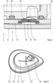
- the bushing seal 18 of the second exemplary embodiment has an actuating projection 34, with the actuating projection 34 being designed in such a way that the bushing seal 18 can be elastically deformed by means of the actuating projection 34 when the coupling piece 14 is transferred into its inserted position.
- the coupling socket 14 thus acts at its transfer into its inserted position and in its inserted position with a force mechanically on the socket seal 18, namely on the actuating projection 34, a.
- the coupling socket 14 presses the socket seal 18 by means of the actuating projection 34 in the respective image plane Figures 5 and 6 down that the negative pressure required for the transfer of the bush seal 18 in its open position is significantly reduced compared to the first embodiment.
- the socket seal 18 is thus designed in such a way that the socket seal 18 can also be transferred from its closed position to its open position by means of a mechanical force exerted by the coupling socket 14 on the socket seal 18 when it is transferred to its inserted position.
- the negative pressure required for transferring the bush seal 18 into its open position is advantageously reduced in this way when the coupling socket 14 is in the inserted position, the negative pressure required for transferring the sleeve seal 18 into its open position remains in place when the coupling socket 14 is in the non-inserted position desirably unaffected by the above modification of the sleeve seal 18, namely the location of the actuating projection 34 on the sleeve seal 18.
- the third exemplary embodiment differs from the first and the second exemplary embodiment, among other things, in its basic mode of operation, which is explained in more detail below.
- the bush seal 18 of this exemplary embodiment is designed in such a way that the bush seal 18 can be converted from its closed position into its open position only by means of a mechanical force exerted by the coupling piece 14 on the bush seal 18 when it is transferred to its inserted position.
- the bush seal 18 is not transferred from its closed position to its open position by a combined effect, namely the mechanical force on the one hand and the negative pressure applied to the bush seal 18 on the other.
- the bush seal 18 is transferred from its closed position to its open position exclusively by the mechanical force of the coupling socket 14 on the bush seal 18, namely the actuating projection 34.
- the actuating projection 34 is dimensioned to be correspondingly large for this purpose.
- the bushing seal 18 of the third embodiment does not have any cross-shaped slots.
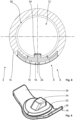
- the bush seal 18 of the present exemplary embodiment has at its edge region, instead of the circumferential connecting section, two diametrically oppositely arranged connecting sections 26, the bush seal 18 being connected by means of the two Connecting portions 26 is connected to the clutch socket 10 in a force-transmitting manner.
- the bush seal 18 is designed here in such a way that the bush seal 18 in its closed position engages with its sealing projection 22 in the flow path opening 24 of the coupling bush 10 in a sealing manner and the sealing projection 22 in the open position of the bush seal 18 is lifted off the flow path opening 24 in a flow-conducting manner.
- the sleeve seal 18 of the third exemplary embodiment is shown in its closed position.
- the coupling socket 14 presses the socket seal 18 by means of the actuating projection 34 in the respective image plane of FIG 7 and 8th so far down that the sealing projection 22 of the bush seal 18 down from its in the 7 and 8th position shown moved into a flow path opening 24 no longer sealing position.
- the bush seal 18 is located in the in the 7 and 8th not shown opening position. If the coupling socket 14 is transferred from its inserted position to its non-inserted position, then the elastic socket seal 18 springs back from its open position to its closed position.
- the two connecting sections 26 of the bush seal 18 have a restoring effect.
- the negative pressure acting when the coupling socket 14 is transferred into its non-inserted position in the socket receptacle 12 is also used specifically for the transfer of the bush seal 18 from its open position to its closed position.
- the above ventilation grooves can be modified for this or, in an alternative embodiment to the present third exemplary embodiment, can be omitted entirely.
- the invention is not limited to the present exemplary embodiments. See, for example, the relevant statements in the introduction to the description.
- the invention is not limited to the design and manufacturing details of the three exemplary embodiments explained.
Landscapes
- Engineering & Computer Science (AREA)
- General Engineering & Computer Science (AREA)
- Mechanical Engineering (AREA)
- Quick-Acting Or Multi-Walled Pipe Joints (AREA)
Applications Claiming Priority (1)
| Application Number | Priority Date | Filing Date | Title |
|---|---|---|---|
| DE102021120587.5A DE102021120587A1 (de) | 2021-08-09 | 2021-08-09 | Ventilfunktionsgruppe für ein flüssigkeitsführendes System und flüssigkeitsführendes System mit einem Haushaltsgerät und einem Flüssigkeitstank |
Publications (3)
| Publication Number | Publication Date |
|---|---|
| EP4134580A1 true EP4134580A1 (fr) | 2023-02-15 |
| EP4134580B1 EP4134580B1 (fr) | 2024-06-12 |
| EP4134580C0 EP4134580C0 (fr) | 2024-06-12 |
Family
ID=82458769
Family Applications (1)
| Application Number | Title | Priority Date | Filing Date |
|---|---|---|---|
| EP22184404.6A Active EP4134580B1 (fr) | 2021-08-09 | 2022-07-12 | Groupe fonctionnel de soupape pour un système guidant du liquide et système guidant du liquide doté d'un tel appareil électroménager et d'un réservoir de liquide |
Country Status (2)
| Country | Link |
|---|---|
| EP (1) | EP4134580B1 (fr) |
| DE (1) | DE102021120587A1 (fr) |
Citations (5)
| Publication number | Priority date | Publication date | Assignee | Title |
|---|---|---|---|---|
| NO325331B1 (no) * | 1995-01-09 | 2008-03-31 | Deb Ip Ltd | Flaske og ventilmontasje for posisjonering av vaesker og sapeautomat |
| KR20090101679A (ko) * | 2008-03-24 | 2009-09-29 | 엘지전자 주식회사 | 의류처리장치 |
| ES2528342T3 (es) * | 2011-01-19 | 2015-02-09 | Miele & Cie. Kg | Dispositivo dosificador para aditivos líquidos y viscosos para una máquina lavadora y máquina lavadora |
| US20200325617A1 (en) * | 2019-04-12 | 2020-10-15 | Lg Electronics Inc. | Washing machine |
| WO2021083678A1 (fr) * | 2019-11-01 | 2021-05-06 | Unilever Ip Holdings B.V. | Récipient à dosage automatique recyclable |
-
2021
- 2021-08-09 DE DE102021120587.5A patent/DE102021120587A1/de not_active Withdrawn
-
2022
- 2022-07-12 EP EP22184404.6A patent/EP4134580B1/fr active Active
Patent Citations (5)
| Publication number | Priority date | Publication date | Assignee | Title |
|---|---|---|---|---|
| NO325331B1 (no) * | 1995-01-09 | 2008-03-31 | Deb Ip Ltd | Flaske og ventilmontasje for posisjonering av vaesker og sapeautomat |
| KR20090101679A (ko) * | 2008-03-24 | 2009-09-29 | 엘지전자 주식회사 | 의류처리장치 |
| ES2528342T3 (es) * | 2011-01-19 | 2015-02-09 | Miele & Cie. Kg | Dispositivo dosificador para aditivos líquidos y viscosos para una máquina lavadora y máquina lavadora |
| US20200325617A1 (en) * | 2019-04-12 | 2020-10-15 | Lg Electronics Inc. | Washing machine |
| WO2021083678A1 (fr) * | 2019-11-01 | 2021-05-06 | Unilever Ip Holdings B.V. | Récipient à dosage automatique recyclable |
Also Published As
| Publication number | Publication date |
|---|---|
| EP4134580B1 (fr) | 2024-06-12 |
| DE102021120587A1 (de) | 2023-02-09 |
| EP4134580C0 (fr) | 2024-06-12 |
Similar Documents
| Publication | Publication Date | Title |
|---|---|---|
| DE10214098B4 (de) | Hochdruck-Schaltventilvorrichtung | |
| DE19818334A1 (de) | Sicherheitsventil für eine Filtervorrichtung und ein Verfahren zur Befestigung desselben | |
| DE102016125134B3 (de) | Quetschventil | |
| DE102007009540A1 (de) | Türverriegelung für ein Haushaltsgerät und Verwendung einer solchen in einem Haushaltsgerät | |
| EP2530365B2 (fr) | Garniture de soupape pour une armature sanitaire | |
| WO2020104504A1 (fr) | Accouplement | |
| WO2018178166A1 (fr) | Dispositif de raccordement pour conduites de fluide | |
| DE10135793C1 (de) | Hydraulikfluidbehälter für eine hydraulische Fahrzeugbremsanlage | |
| EP4134580B1 (fr) | Groupe fonctionnel de soupape pour un système guidant du liquide et système guidant du liquide doté d'un tel appareil électroménager et d'un réservoir de liquide | |
| DE102005003982A1 (de) | Pneumatisches Wegeventil mit einem Ventilschieber | |
| EP1513721A1 (fr) | Bouchon d'obturation | |
| DE102022101100A1 (de) | Fluidverbindung | |
| DE102006056553A1 (de) | Einfüllstutzen für den Kraftstofftank eines Kraftfahrzeugs | |
| CH689321A5 (de) | Sichtfenster. | |
| EP3028738A1 (fr) | Bride de serrage pour tuyaux | |
| WO2012076359A1 (fr) | Réservoir de compensation pour systèmes de freinage hydrauliques de véhicules à moteur | |
| DE102019218338A1 (de) | Steckverbindungsanordnung | |
| DE102024107949A1 (de) | Gehäusekasten | |
| DE102006042502A1 (de) | Zweiteiliges Ventil | |
| DE10049328B4 (de) | Betätigungsaufsatz für ein Ventil und zugehöriger Bausatz | |
| DE60027072T2 (de) | Elektrische Steckverbindung, insbesondere für Kraftfahrzeuganwendungen | |
| EP4119848A1 (fr) | Dispositif de commande d'un appareil électroménager et appareil électroménager | |
| EP3459804B1 (fr) | Valve et système de freinage pneumatique | |
| EP1707863A1 (fr) | Pièce de raccord pour un raccord enfichable pour fluide sous pression | |
| DE102023133789A1 (de) | Auslaufstoppventil, insbesondere für eine Steckverbindung |
Legal Events
| Date | Code | Title | Description |
|---|---|---|---|
| PUAI | Public reference made under article 153(3) epc to a published international application that has entered the european phase |
Free format text: ORIGINAL CODE: 0009012 |
|
| STAA | Information on the status of an ep patent application or granted ep patent |
Free format text: STATUS: THE APPLICATION HAS BEEN PUBLISHED |
|
| AK | Designated contracting states |
Kind code of ref document: A1 Designated state(s): AL AT BE BG CH CY CZ DE DK EE ES FI FR GB GR HR HU IE IS IT LI LT LU LV MC MK MT NL NO PL PT RO RS SE SI SK SM TR |
|
| STAA | Information on the status of an ep patent application or granted ep patent |
Free format text: STATUS: REQUEST FOR EXAMINATION WAS MADE |
|
| 17P | Request for examination filed |
Effective date: 20230816 |
|
| RBV | Designated contracting states (corrected) |
Designated state(s): AL AT BE BG CH CY CZ DE DK EE ES FI FR GB GR HR HU IE IS IT LI LT LU LV MC MK MT NL NO PL PT RO RS SE SI SK SM TR |
|
| GRAP | Despatch of communication of intention to grant a patent |
Free format text: ORIGINAL CODE: EPIDOSNIGR1 |
|
| STAA | Information on the status of an ep patent application or granted ep patent |
Free format text: STATUS: GRANT OF PATENT IS INTENDED |
|
| RIC1 | Information provided on ipc code assigned before grant |
Ipc: F16L 27/12 20060101ALI20240201BHEP Ipc: F16L 27/087 20060101ALI20240201BHEP Ipc: F16K 15/14 20060101ALI20240201BHEP Ipc: D06F 39/02 20060101ALI20240201BHEP Ipc: F16L 55/11 20060101AFI20240201BHEP |
|
| INTG | Intention to grant announced |
Effective date: 20240229 |
|
| GRAS | Grant fee paid |
Free format text: ORIGINAL CODE: EPIDOSNIGR3 |
|
| GRAA | (expected) grant |
Free format text: ORIGINAL CODE: 0009210 |
|
| STAA | Information on the status of an ep patent application or granted ep patent |
Free format text: STATUS: THE PATENT HAS BEEN GRANTED |
|
| AK | Designated contracting states |
Kind code of ref document: B1 Designated state(s): AL AT BE BG CH CY CZ DE DK EE ES FI FR GB GR HR HU IE IS IT LI LT LU LV MC MK MT NL NO PL PT RO RS SE SI SK SM TR |
|
| REG | Reference to a national code |
Ref country code: GB Ref legal event code: FG4D Free format text: NOT ENGLISH |
|
| REG | Reference to a national code |
Ref country code: CH Ref legal event code: EP |
|
| REG | Reference to a national code |
Ref country code: IE Ref legal event code: FG4D Free format text: LANGUAGE OF EP DOCUMENT: GERMAN |
|
| REG | Reference to a national code |
Ref country code: DE Ref legal event code: R096 Ref document number: 502022001024 Country of ref document: DE |
|
| U01 | Request for unitary effect filed |
Effective date: 20240612 |
|
| U07 | Unitary effect registered |
Designated state(s): AT BE BG DE DK EE FI FR IT LT LU LV MT NL PT SE SI Effective date: 20240618 |
|
| REG | Reference to a national code |
Ref country code: GB Ref legal event code: 746 Effective date: 20240703 |
|
| PG25 | Lapsed in a contracting state [announced via postgrant information from national office to epo] |
Ref country code: HR Free format text: LAPSE BECAUSE OF FAILURE TO SUBMIT A TRANSLATION OF THE DESCRIPTION OR TO PAY THE FEE WITHIN THE PRESCRIBED TIME-LIMIT Effective date: 20240612 |
|
| PG25 | Lapsed in a contracting state [announced via postgrant information from national office to epo] |
Ref country code: GR Free format text: LAPSE BECAUSE OF FAILURE TO SUBMIT A TRANSLATION OF THE DESCRIPTION OR TO PAY THE FEE WITHIN THE PRESCRIBED TIME-LIMIT Effective date: 20240913 |
|
| PG25 | Lapsed in a contracting state [announced via postgrant information from national office to epo] |
Ref country code: ES Free format text: LAPSE BECAUSE OF FAILURE TO SUBMIT A TRANSLATION OF THE DESCRIPTION OR TO PAY THE FEE WITHIN THE PRESCRIBED TIME-LIMIT Effective date: 20240612 |
|
| U20 | Renewal fee for the european patent with unitary effect paid |
Year of fee payment: 3 Effective date: 20240918 |
|
| PG25 | Lapsed in a contracting state [announced via postgrant information from national office to epo] |
Ref country code: NO Free format text: LAPSE BECAUSE OF FAILURE TO SUBMIT A TRANSLATION OF THE DESCRIPTION OR TO PAY THE FEE WITHIN THE PRESCRIBED TIME-LIMIT Effective date: 20240912 Ref country code: HR Free format text: LAPSE BECAUSE OF FAILURE TO SUBMIT A TRANSLATION OF THE DESCRIPTION OR TO PAY THE FEE WITHIN THE PRESCRIBED TIME-LIMIT Effective date: 20240612 Ref country code: GR Free format text: LAPSE BECAUSE OF FAILURE TO SUBMIT A TRANSLATION OF THE DESCRIPTION OR TO PAY THE FEE WITHIN THE PRESCRIBED TIME-LIMIT Effective date: 20240913 Ref country code: ES Free format text: LAPSE BECAUSE OF FAILURE TO SUBMIT A TRANSLATION OF THE DESCRIPTION OR TO PAY THE FEE WITHIN THE PRESCRIBED TIME-LIMIT Effective date: 20240612 Ref country code: RS Free format text: LAPSE BECAUSE OF FAILURE TO SUBMIT A TRANSLATION OF THE DESCRIPTION OR TO PAY THE FEE WITHIN THE PRESCRIBED TIME-LIMIT Effective date: 20240912 |
|
| PG25 | Lapsed in a contracting state [announced via postgrant information from national office to epo] |
Ref country code: PL Free format text: LAPSE BECAUSE OF FAILURE TO SUBMIT A TRANSLATION OF THE DESCRIPTION OR TO PAY THE FEE WITHIN THE PRESCRIBED TIME-LIMIT Effective date: 20240612 |
|
| PG25 | Lapsed in a contracting state [announced via postgrant information from national office to epo] |
Ref country code: IS Free format text: LAPSE BECAUSE OF FAILURE TO SUBMIT A TRANSLATION OF THE DESCRIPTION OR TO PAY THE FEE WITHIN THE PRESCRIBED TIME-LIMIT Effective date: 20241012 |
|
| PG25 | Lapsed in a contracting state [announced via postgrant information from national office to epo] |
Ref country code: CZ Free format text: LAPSE BECAUSE OF FAILURE TO SUBMIT A TRANSLATION OF THE DESCRIPTION OR TO PAY THE FEE WITHIN THE PRESCRIBED TIME-LIMIT Effective date: 20240612 |
|
| PG25 | Lapsed in a contracting state [announced via postgrant information from national office to epo] |
Ref country code: RO Free format text: LAPSE BECAUSE OF FAILURE TO SUBMIT A TRANSLATION OF THE DESCRIPTION OR TO PAY THE FEE WITHIN THE PRESCRIBED TIME-LIMIT Effective date: 20240612 Ref country code: SK Free format text: LAPSE BECAUSE OF FAILURE TO SUBMIT A TRANSLATION OF THE DESCRIPTION OR TO PAY THE FEE WITHIN THE PRESCRIBED TIME-LIMIT Effective date: 20240612 |
|
| PG25 | Lapsed in a contracting state [announced via postgrant information from national office to epo] |
Ref country code: SM Free format text: LAPSE BECAUSE OF FAILURE TO SUBMIT A TRANSLATION OF THE DESCRIPTION OR TO PAY THE FEE WITHIN THE PRESCRIBED TIME-LIMIT Effective date: 20240612 |
|
| PG25 | Lapsed in a contracting state [announced via postgrant information from national office to epo] |
Ref country code: SM Free format text: LAPSE BECAUSE OF FAILURE TO SUBMIT A TRANSLATION OF THE DESCRIPTION OR TO PAY THE FEE WITHIN THE PRESCRIBED TIME-LIMIT Effective date: 20240612 Ref country code: SK Free format text: LAPSE BECAUSE OF FAILURE TO SUBMIT A TRANSLATION OF THE DESCRIPTION OR TO PAY THE FEE WITHIN THE PRESCRIBED TIME-LIMIT Effective date: 20240612 Ref country code: RO Free format text: LAPSE BECAUSE OF FAILURE TO SUBMIT A TRANSLATION OF THE DESCRIPTION OR TO PAY THE FEE WITHIN THE PRESCRIBED TIME-LIMIT Effective date: 20240612 Ref country code: PL Free format text: LAPSE BECAUSE OF FAILURE TO SUBMIT A TRANSLATION OF THE DESCRIPTION OR TO PAY THE FEE WITHIN THE PRESCRIBED TIME-LIMIT Effective date: 20240612 Ref country code: IS Free format text: LAPSE BECAUSE OF FAILURE TO SUBMIT A TRANSLATION OF THE DESCRIPTION OR TO PAY THE FEE WITHIN THE PRESCRIBED TIME-LIMIT Effective date: 20241012 Ref country code: CZ Free format text: LAPSE BECAUSE OF FAILURE TO SUBMIT A TRANSLATION OF THE DESCRIPTION OR TO PAY THE FEE WITHIN THE PRESCRIBED TIME-LIMIT Effective date: 20240612 |
|
| PG25 | Lapsed in a contracting state [announced via postgrant information from national office to epo] |
Ref country code: MC Free format text: LAPSE BECAUSE OF FAILURE TO SUBMIT A TRANSLATION OF THE DESCRIPTION OR TO PAY THE FEE WITHIN THE PRESCRIBED TIME-LIMIT Effective date: 20240612 |
|
| PG25 | Lapsed in a contracting state [announced via postgrant information from national office to epo] |
Ref country code: MC Free format text: LAPSE BECAUSE OF FAILURE TO SUBMIT A TRANSLATION OF THE DESCRIPTION OR TO PAY THE FEE WITHIN THE PRESCRIBED TIME-LIMIT Effective date: 20240612 |
|
| PLBE | No opposition filed within time limit |
Free format text: ORIGINAL CODE: 0009261 |
|
| STAA | Information on the status of an ep patent application or granted ep patent |
Free format text: STATUS: NO OPPOSITION FILED WITHIN TIME LIMIT |
|
| 26N | No opposition filed |
Effective date: 20250313 |
|
| PG25 | Lapsed in a contracting state [announced via postgrant information from national office to epo] |
Ref country code: IE Free format text: LAPSE BECAUSE OF NON-PAYMENT OF DUE FEES Effective date: 20240712 |
|
| U20 | Renewal fee for the european patent with unitary effect paid |
Year of fee payment: 4 Effective date: 20250731 |
|
| PGFP | Annual fee paid to national office [announced via postgrant information from national office to epo] |
Ref country code: TR Payment date: 20250702 Year of fee payment: 4 |
|
| PG25 | Lapsed in a contracting state [announced via postgrant information from national office to epo] |
Ref country code: CY Free format text: LAPSE BECAUSE OF FAILURE TO SUBMIT A TRANSLATION OF THE DESCRIPTION OR TO PAY THE FEE WITHIN THE PRESCRIBED TIME-LIMIT; INVALID AB INITIO Effective date: 20220712 |
|
| REG | Reference to a national code |
Ref country code: CH Ref legal event code: H13 Free format text: ST27 STATUS EVENT CODE: U-0-0-H10-H13 (AS PROVIDED BY THE NATIONAL OFFICE) Effective date: 20260224 |
|
| PG25 | Lapsed in a contracting state [announced via postgrant information from national office to epo] |
Ref country code: HU Free format text: LAPSE BECAUSE OF FAILURE TO SUBMIT A TRANSLATION OF THE DESCRIPTION OR TO PAY THE FEE WITHIN THE PRESCRIBED TIME-LIMIT; INVALID AB INITIO Effective date: 20220712 |
|
| PG25 | Lapsed in a contracting state [announced via postgrant information from national office to epo] |
Ref country code: CH Free format text: LAPSE BECAUSE OF NON-PAYMENT OF DUE FEES Effective date: 20250731 |