EP4134580B1 - Groupe fonctionnel de soupape pour un système guidant du liquide et système guidant du liquide doté d'un tel appareil électroménager et d'un réservoir de liquide - Google Patents
Groupe fonctionnel de soupape pour un système guidant du liquide et système guidant du liquide doté d'un tel appareil électroménager et d'un réservoir de liquide Download PDFInfo
- Publication number
- EP4134580B1 EP4134580B1 EP22184404.6A EP22184404A EP4134580B1 EP 4134580 B1 EP4134580 B1 EP 4134580B1 EP 22184404 A EP22184404 A EP 22184404A EP 4134580 B1 EP4134580 B1 EP 4134580B1
- Authority
- EP
- European Patent Office
- Prior art keywords
- coupling
- valve function
- function group
- seal
- connecting piece
- Prior art date
- Legal status (The legal status is an assumption and is not a legal conclusion. Google has not performed a legal analysis and makes no representation as to the accuracy of the status listed.)
- Active
Links
Images


Classifications
-
- F—MECHANICAL ENGINEERING; LIGHTING; HEATING; WEAPONS; BLASTING
- F16—ENGINEERING ELEMENTS AND UNITS; GENERAL MEASURES FOR PRODUCING AND MAINTAINING EFFECTIVE FUNCTIONING OF MACHINES OR INSTALLATIONS; THERMAL INSULATION IN GENERAL
- F16L—PIPES; JOINTS OR FITTINGS FOR PIPES; SUPPORTS FOR PIPES, CABLES OR PROTECTIVE TUBING; MEANS FOR THERMAL INSULATION IN GENERAL
- F16L55/00—Devices or appurtenances for use in, or in connection with, pipes or pipe systems
- F16L55/10—Means for stopping flow in pipes or hoses
- F16L55/11—Plugs
-
- F—MECHANICAL ENGINEERING; LIGHTING; HEATING; WEAPONS; BLASTING
- F16—ENGINEERING ELEMENTS AND UNITS; GENERAL MEASURES FOR PRODUCING AND MAINTAINING EFFECTIVE FUNCTIONING OF MACHINES OR INSTALLATIONS; THERMAL INSULATION IN GENERAL
- F16K—VALVES; TAPS; COCKS; ACTUATING-FLOATS; DEVICES FOR VENTING OR AERATING
- F16K15/00—Check valves
- F16K15/14—Check valves with flexible valve members
- F16K15/144—Check valves with flexible valve members the closure elements being fixed along all or a part of their periphery
- F16K15/147—Check valves with flexible valve members the closure elements being fixed along all or a part of their periphery the closure elements having specially formed slits or being of an elongated easily collapsible form
- F16K15/1471—Check valves with flexible valve members the closure elements being fixed along all or a part of their periphery the closure elements having specially formed slits or being of an elongated easily collapsible form slits arranged along multiple axes
-
- F—MECHANICAL ENGINEERING; LIGHTING; HEATING; WEAPONS; BLASTING
- F16—ENGINEERING ELEMENTS AND UNITS; GENERAL MEASURES FOR PRODUCING AND MAINTAINING EFFECTIVE FUNCTIONING OF MACHINES OR INSTALLATIONS; THERMAL INSULATION IN GENERAL
- F16L—PIPES; JOINTS OR FITTINGS FOR PIPES; SUPPORTS FOR PIPES, CABLES OR PROTECTIVE TUBING; MEANS FOR THERMAL INSULATION IN GENERAL
- F16L27/00—Adjustable joints; Joints allowing movement
- F16L27/08—Adjustable joints; Joints allowing movement allowing adjustment or movement only about the axis of one pipe
- F16L27/087—Joints with radial fluid passages
-
- F—MECHANICAL ENGINEERING; LIGHTING; HEATING; WEAPONS; BLASTING
- F16—ENGINEERING ELEMENTS AND UNITS; GENERAL MEASURES FOR PRODUCING AND MAINTAINING EFFECTIVE FUNCTIONING OF MACHINES OR INSTALLATIONS; THERMAL INSULATION IN GENERAL
- F16L—PIPES; JOINTS OR FITTINGS FOR PIPES; SUPPORTS FOR PIPES, CABLES OR PROTECTIVE TUBING; MEANS FOR THERMAL INSULATION IN GENERAL
- F16L27/00—Adjustable joints; Joints allowing movement
- F16L27/12—Adjustable joints; Joints allowing movement allowing substantial longitudinal adjustment or movement
-
- D—TEXTILES; PAPER
- D06—TREATMENT OF TEXTILES OR THE LIKE; LAUNDERING; FLEXIBLE MATERIALS NOT OTHERWISE PROVIDED FOR
- D06F—LAUNDERING, DRYING, IRONING, PRESSING OR FOLDING TEXTILE ARTICLES
- D06F39/00—Details of washing machines not specific to a single type of machines covered by groups D06F9/00 - D06F27/00
- D06F39/02—Devices for adding soap or other washing agents
- D06F39/022—Devices for adding soap or other washing agents in a liquid state
Definitions
- the invention relates to a valve function group for a liquid-conducting system and a liquid-conducting system with a household appliance and a liquid tank.
- valve function groups for liquid-conducting systems and liquid-conducting systems with a household appliance and a liquid tank are already known from the prior art in a large number of embodiments.
- these valve function groups serve to seal the liquid tank whenever the liquid tank is not connected to the household appliance in a flow-conducting manner.
- the valve function groups fulfill the purpose of being able to connect the liquid tank to the household appliance in a flow-conducting manner.
- valve function groups can be found in the US 2020/325617 A1 and in the WO 2021/083678 A1 .
- the invention therefore addresses the problem of improving a valve function group for a liquid-conducting system and a liquid-conducting system with a household appliance and a liquid tank.
- valve function group with the features of patent claim 1, according to which the valve function group comprises a coupling bushing for the flow-conducting connection of the valve function group to the liquid tank and a coupling nozzle, which is inserted in a plug-in position in a nozzle receptacle of the coupling bushing in a flow-conducting manner, for the flow-conducting connection of the valve function group to the household appliance, wherein the coupling bushing has a bushing seal that can be transferred back and forth between a closed position that blocks a flow path that connects the liquid tank to the nozzle receptacle in a flow-conducting manner and an open position that opens the flow path, and the flow path can be blocked in its closed position and opened in its open position only by means of an elastic deformation of the bushing seal.
- the household appliance can be, for example, a washing machine for textiles.
- the liquid-conducting system can also be a commercial appliance, i.e. a device for the professional use.
- valve function group for a liquid-conducting system with a household appliance and a liquid tank is improved. Due to the inventive design of the valve function group, it is possible to significantly reduce the structural complexity of the valve function group. Accordingly, the manufacture of the valve function group is simplified. On the other hand, the number of components is also reduced, so that logistics and storage are also simplified. All in all, the valve function group according to the invention can be manufactured much more cost-effectively and with reduced weight. Furthermore, the valve function group according to the invention can also be realized with a smaller number of different materials. Accordingly, the recyclability of the valve function group is significantly improved.
- valve function group according to the invention can be freely selected within wide, suitable limits in terms of type, mode of operation, material and dimensions. See, for example, the relevant statements in the introduction to the description.
- valve function group according to the invention provides that the bushing seal is designed in such a way that the bushing seal can be moved from its closed position to its open position by means of a mechanical force effect of the coupling socket on the bushing seal when it is transferred to its inserted position, preferably only by means of the aforementioned force effect.
- the valve function group according to the invention can be implemented in a structurally and manufacturing-technically simple manner and in a robust manner. This applies in particular to the preferred embodiment of this development.
- the bushing seal has an actuating projection, wherein the actuating projection is designed such that the bushing seal can be elastically deformed by means of the actuating projection, preferably only by means of the actuating projection, when the coupling socket is transferred into its inserted position.
- the actuating projection can protrude from a remainder of the bushing seal by a corresponding distance.
- the actuating projection makes it possible to have the coupling socket act on the bushing seal in a targeted manner, so that the force effect on the bushing seal is very defined.
- the bushing seal can be freely selected in terms of type, function, material and dimensions within wide suitable limits.
- a further advantageous development of the valve function group according to the invention provides that the bushing seal is designed as a squeeze element with at least one slot. Squeeze elements are available on the market in a large number of designs and can therefore be used for a wide variety of applications.
- the bushing seal is designed in such a way that the bushing seal in its closed position engages with a sealing projection in a flow path opening of the coupling bushing, preferably that the sealing projection can be at least partially lifted off the flow path opening in a flow-conducting manner when the bushing seal is transferred to its open position.
- the sealing effect of the bushing seal is significantly improved.
- the preferred embodiment of this development has the further advantage that the bushing seal can be transferred to its open position without additional structural adjustments to the bushing seal, for example without slots that can be opened in a flow-conducting manner using negative pressure.
- valve function group provides that the bushing seal has a circumferential connecting section or at least two connecting sections arranged diametrically opposite one another at its edge region, wherein the bushing seal is connected to the coupling bushing in a force-transmitting manner by means of the at least one connecting section.
- the bushing seal can be connected to the coupling bushing in a particularly simple manner in terms of design and production technology.
- the valve function group according to the invention provides that the socket seal is designed in such a way that the socket seal in the inserted position can be transferred from its closed position to its open position and/or from its open position to its closed position by means of a negative pressure applied to the socket seal, preferably only by means of a negative pressure. In this way, it is possible for the socket seal to be transferred from its closed position to its open position only when actually required. Accordingly, inserting the coupling socket into the plug-in receptacle of the coupling socket, for example plugging the liquid tank with the coupling socket onto the coupling socket of the household appliance, only serves to prepare the actual flow-conducting connection between the liquid tank on the one side and the household appliance on the other. the other side. Only when the negative pressure is applied is the bushing seal moved from its closed position to its open position, thus opening the flow path between the liquid tank and the nozzle holder.
- valve function group provides that two circumferential nozzle seals are designed to be adapted to the nozzle receptacle and arranged on the coupling nozzle in such a way that a negative pressure can be built up by means of the coupling nozzle in its inserted position in the nozzle receptacle in such a way that the socket seal can be transferred to its open position by means of this negative pressure.
- This makes it possible, in a structurally and manufacturing-technically simple manner, to build up sufficient negative pressure on the socket seal by means of the coupling nozzle to transfer it to its open position.
- valve function group provides that two circumferential nozzle seals are arranged on the coupling nozzle for sealing the nozzle receptacle in an area between the two nozzle seals when the coupling nozzle is in its inserted position and two circumferential ventilation grooves are arranged on the coupling bushing, wherein the nozzle seals and the ventilation grooves are designed and arranged in such a way that they correspond to one another that a negative pressure acting between the coupling bushing and the coupling nozzle can be reduced when the coupling nozzle is transferred to a non-inserted position of the coupling nozzle in which the coupling nozzle is not inserted into the nozzle receptacle.
- valve function group additionally comprises a transport nozzle, wherein the transport nozzle is designed to be adapted to the nozzle receptacle of the coupling bushing with the bushing seal arranged thereon in such a way that the bushing seal can be secured in its closed position when the transport nozzle is inserted into the nozzle receptacle.
- the bushing seal can be secured in its closed position in a robust manner. This is particularly important when transporting the liquid tank.
- the liquid-conducting system according to the invention can be freely selected within wide, suitable limits in terms of type, function, material and dimensions. See, for example, the relevant statements in the introduction to the description. It is advantageously provided that the coupling socket is designed as an integral component of the household appliance and the coupling socket as an integral component of the liquid tank. In this way, the complexity of the liquid-conducting system according to the invention is significantly reduced. Handling is correspondingly simplified for a user of the liquid-conducting system according to the invention. The ease of use for the user is improved.
- a first embodiment of the liquid-conducting system according to the invention with the valve function group according to the invention is shown purely by way of example.
- the liquid-conducting system 2 has a household appliance 4 designed as a washing machine for textiles, a liquid tank 6 designed as a detergent cartridge with detergent (not shown), and a valve function group 8 for optionally connecting the liquid tank 6 to or separating the liquid tank 6 from the household appliance 4.
- a household appliance 4 designed as a washing machine for textiles
- a liquid tank 6 designed as a detergent cartridge with detergent (not shown)
- a valve function group 8 for optionally connecting the liquid tank 6 to or separating the liquid tank 6 from the household appliance 4.
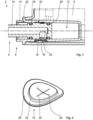
- the valve function group 8 for the liquid-conducting system 2 comprises a coupling bush 10 for the flow-conducting connection of the valve function group 8 with the liquid tank 6 and a Fig.1 and 3 shown insertion position in a nozzle receptacle 12 of the coupling socket 10, a coupling socket 14 for the flow-conducting connection of the valve function group 8 to the household appliance 4, wherein the coupling socket 10 has a bushing seal 18 which can be transferred back and forth between a closed position blocking a flow path 16 connecting the liquid tank 6 to the nozzle receptacle 12 in a flow-conducting manner and an open position opening the flow path 16, and the flow path 16 can be opened only by means of an elastic deformation of the bushing seal 18 in its Fig. 1 to 4 can be blocked in the closed position shown and opened in the open position not shown.
- the coupling nozzle 14 is designed as an integral component of the household appliance 4 and the coupling bushing 10 is designed as an integral component of the liquid tank 6. Both the coupling bushing 10 and the coupling nozzle 14 are each made of a thermoplastic.
- the bushing seal 18 is designed here as a squeeze element made of an elastomer with two cross-arranged slots 20. See the Fig.2 , in which the bushing seal 18 is shown in its closed position. Furthermore, the bushing seal 18 is designed such that the bushing seal 18 in its closed position and in its open position engages with a sealing projection 22 in a flow path opening 24 of the coupling bushing 10. In addition, the bushing seal 18 has a circumferential connecting section 26 on its edge area, wherein the bushing seal 18 is connected to the coupling bushing 10 in a force-transmitting manner by means of the connecting section 26.
- connection techniques are available to the expert for this purpose. Purely by way of example, reference is made here to multi-component injection molding or locking by means of a fastening ring or the like.
- the bushing seal 18 is designed such that the bushing seal 18 can be moved from its closed position into its open position by means of a negative pressure applied to the bushing seal 18, namely only by means of the negative pressure.
- the tabs of the bushing seal 18 formed by the two cross-shaped slots 20 are released from the position in the Fig.2 shown position, so that the flow path 16, namely the flow path opening 24 of the coupling bush 10, is opened.
- the aforementioned tabs return to the position shown in the Fig.2 visible position so that the bushing seal 18 is again in its closed position. The flow path 16 is blocked again.
- two circumferential nozzle seals 28 are designed to be adapted to the nozzle receptacle 12 and are arranged on the coupling nozzle 14 in such a way that a negative pressure can be built up by means of the coupling nozzle 14 in its inserted position in the nozzle receptacle 12 in such a way that the bushing seal 18 can be transferred into its open position by means of this negative pressure.
- two circumferential ventilation grooves 30 are arranged on the coupling bushing 10 in an area between the two nozzle seals 28 when the coupling nozzle 14 is in its inserted position, wherein the nozzle seals 28 and the ventilation grooves 30 are designed and arranged to correspond to one another in such a way that a negative pressure acting between the coupling bushing 10 and the coupling nozzle 14 can be reduced when the coupling nozzle 14 is transferred to a non-inserted position of the coupling nozzle 14, in which the coupling nozzle 14 is not inserted into the nozzle receptacle 12.
- valve function group 8 of the present embodiment also comprises a transport nozzle 32 made of thermoplastic, wherein the transport nozzle 32 is designed to be adapted to the nozzle receptacle 12 of the coupling bush 10 with the bush seal 18 arranged thereon, such that the bush seal 18 can be secured in its closed position when the transport nozzle 32 is inserted into the nozzle receptacle 12.
- a transport nozzle 32 made of thermoplastic, wherein the transport nozzle 32 is designed to be adapted to the nozzle receptacle 12 of the coupling bush 10 with the bush seal 18 arranged thereon, such that the bush seal 18 can be secured in its closed position when the transport nozzle 32 is inserted into the nozzle receptacle 12.
- Fig.4 in which the transport nozzle 32 is shown in an inserted position of the transport nozzle 32, in which the transport nozzle 32, analogous to the coupling nozzle 14, is inserted into the nozzle receptacle 12.
- the coupling socket 14 is in its non-inserted position.
- the liquid tank 6 with the coupling socket 10 arranged on it is therefore not yet connected to the household appliance 4 with the coupling nozzle 14 arranged thereon in a flow-conducting manner.
- the transport nozzle 32 is inserted into the nozzle receptacle 12 of the coupling socket 10. A deformation of the socket seal 18 in the direction of its open position, for example due to an overpressure prevailing in the liquid tank 6, is effectively prevented by means of the transport nozzle 32. See the Fig.4 .
- a user of the liquid-conducting system 2 first removes the transport nozzle 32 by the user positioning the transport nozzle 32 in the image plane of the Fig.4 from right to left out of the socket receptacle 12 of the coupling bush 10.
- the bush seal 18 is not opened, i.e. transferred to its open position, but remains in its Fig.2 shown closed position.
- the user now attaches the liquid tank 6 to the coupling socket 14 of the household appliance 4 using the coupling socket 10, so that the coupling socket 14 fits into the Fig.1 and 3 shown in the insertion position.
- the insertion position of the coupling socket 14 it rests tightly against the socket receptacle 12 of the coupling bush 10 by means of the socket seals 28.
- the bushing seal 18 is arranged in an area of the coupling bushing 10 in which the nozzle receptacle 12 is sealed by means of the nozzle seals 28 against a remainder of the nozzle receptacle 12.
- the bushing seal 18 remains in its Fig.2 shown closed position.
- a negative pressure is generated on the bushing seal 18, so that the bushing seal 18 is transferred from its closed position to its open position by means of the negative pressure in the manner explained above.
- the detergent stored in the liquid tank 6 can now flow from the liquid tank 6 through the coupling nozzle 14 into the household appliance 4 by means of the opened flow path 16.
- the negative pressure required to transfer the bushing seal 18 to its open position can be adjusted, for example, by the material thickness and the geometry of the bushing seal 18.
- the user wants to remove the liquid tank 6 from the household appliance 4, he moves the coupling nozzle 14 from its inserted position to its non-inserted position.
- the coupling nozzle 14 is moved to its non-inserted position, a gap is created in the area shown in the image plane of the Fig.1
- This undesirable negative pressure is, however, broken by the fact that the ventilation grooves 30 corresponding to the nozzle seals 28 are arranged in the coupling bushing 10.
- the nozzle seals 28 come into engagement with the respective ventilation groove 30 so that the negative pressure prevailing in the aforementioned part of the nozzle holder 12 is equalized.
- the user can now very easily remove the coupling nozzle 14 from the nozzle holder 12 so that the liquid tank 6 can be easily separated from the household appliance 4 by the user.
- the nozzle seals 28 and the ventilation grooves 30 are dimensioned and arranged in such a way that when the coupling nozzle 14 is transferred to its non-inserted position, an undesired transfer of the socket seal 18 to its open position due to the aforementioned negative pressure is reliably prevented.
- FIG. 5 to 9 Two further embodiments of the fluid-conducting system according to the invention with the valve function group according to the invention are explained by way of example. Identical or equivalent components are provided with the same reference numerals. Furthermore, the further embodiments are each explained only to the extent that they differ from the preceding embodiments, in particular from the first embodiment. Otherwise, reference is made to the explanations for the respective aforementioned embodiments, in particular to the above explanations for the first embodiment.
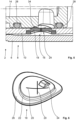
- the bushing seal 18 of the second embodiment has an actuating projection 34, wherein the actuating projection 34 is designed such that the bushing seal 18 is elastically deformable by means of the actuating projection 34 when the coupling socket 14 is transferred into its inserted position.
- the coupling socket 14 therefore acts its transfer into its insertion position and in its insertion position with a force mechanically onto the bushing seal 18, namely onto its actuating projection 34.
- the coupling socket 14 presses the bushing seal 18 by means of the actuating projection 34 in such a way in the respective image plane of the Fig. 5 and 6 downwards, such that the negative pressure required to transfer the bushing seal 18 into its open position is significantly reduced in comparison to the first exemplary embodiment.
- the bushing seal 18 is thus designed in such a way that the bushing seal 18 can also be transferred from the closed position to the open position by means of a mechanical force acting on the bushing seal 18 when the bushing seal 18 is transferred into its inserted position.
- the negative pressure required to transfer the bushing seal 18 into its open position when the coupling socket 14 is in the inserted position is advantageously reduced in this way, the negative pressure required to transfer the bushing seal 18 into its open position when the coupling socket 14 is in the non-inserted position remains unaffected in the desired manner by the above-mentioned modification of the bushing seal 18, namely by the arrangement of the actuating projection 34 on the bushing seal 18.
- the third embodiment differs from the first and second embodiments in its basic mode of operation, which is explained in more detail below.
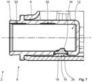
- the bushing seal 18 of this embodiment is designed in such a way that the bushing seal 18 can be moved from its closed position to its open position simply by means of a mechanical force applied by the coupling socket 14 on the bushing seal 18 when it is moved into its inserted position. Unlike in the second embodiment, the bushing seal 18 is therefore not moved from its closed position to its open position by a combined effect, namely the mechanical force applied on the one hand and the negative pressure applied to the bushing seal 18 on the other. Instead, the bushing seal 18 is moved from its closed position to its open position exclusively by the mechanical force applied by the coupling socket 14 on the bushing seal 18, namely the actuating projection 34.
- the actuating projection 34 is dimensioned accordingly large for this purpose.
- the bushing seal 18 of the third embodiment does not have any cross-shaped slots.
- the bushing seal 18 of the present embodiment has two diametrically opposed connecting sections 26 at its edge region instead of the circumferential connecting section, the bushing seal 18 being connected by means of the two connecting sections 26 is connected to the coupling bush 10 in a force-transmitting manner.
- the bush seal 18 is designed here in such a way that the bush seal 18 in its closed position with its sealing projection 22 engages in the flow path opening 24 of the coupling bush 10 and the sealing projection 22 in the open position of the bush seal 18 is lifted off the flow path opening 24 in a flow-conducting manner.
- the bushing seal 18 of the third embodiment is shown in its closed position.
- the coupling socket 14 presses the bushing seal 18 by means of the actuating projection 34 in the respective image plane of the Fig.7 and 8th so far downwards that the sealing projection 22 of the bushing seal 18 moves downwards out of its Fig.7 and 8th shown position into a position that no longer seals the flow path opening 24.
- the bushing seal 18 is in its Fig.7 and 8th not shown open position. If the coupling socket 14 is transferred from its inserted position to its non-inserted position, the elastic bushing seal 18 springs back from its open position to its closed position.
- the two connecting sections 26 of the bushing seal 18 in particular have a restoring effect.
- the negative pressure acting when the coupling socket 14 is transferred to its non-inserted position in the socket receptacle 12 is specifically used additionally to transfer the bushing seal 18 from its open position to its closed position.
- the above ventilation grooves can be modified for this purpose or, in an alternative embodiment to the present third exemplary embodiment, can be omitted entirely.
Landscapes
- Engineering & Computer Science (AREA)
- General Engineering & Computer Science (AREA)
- Mechanical Engineering (AREA)
- Quick-Acting Or Multi-Walled Pipe Joints (AREA)
Claims (11)
- Groupe fonctionnel de soupape (8) destiné à un système de transport de liquide (2) comportant un appareil électroménager (4) et un réservoir de liquide (6) pour, au choix, le raccordement d'une manière conductrice d'écoulement du réservoir de liquide (6) à l'appareil électroménager (4) ou la séparation d'une manière conductrice d'écoulement du réservoir de liquide (6) dudit appareil électroménager, comprenant une douille d'accouplement (10) pour le raccordement d'une manière conductrice d'écoulement du groupe fonctionnel de soupape (8) au réservoir de liquide (6) et une tubulure d'accouplement (14) insérée de manière conductrice d'écoulement dans une position d'insertion dans un logement pour tubulure (12) de la douille d'accouplement (10) pour le raccordement d'une manière conductrice d'écoulement du groupe fonctionnel de soupape (8) à l'appareil électroménager (4), dans lequel la douille d'accouplement (10) présente un joint de douille (18) pouvant être transféré en va-et-vient entre une position de fermeture bloquant une voie d'écoulement (16) raccordant de manière conductrice d'écoulement le réservoir de liquide (6) au logement pour tubulure (12) et une position d'ouverture ouvrant la voie d'écoulement (16), et la voie d'écoulement (16) peut être bloquée dans la position de fermeture dudit joint de douille et être ouverte dans la position d'ouverture dudit joint de douille uniquement au moyen d'une déformation élastique du joint de douille (18),
caractérisé en ce que
le joint de douille (18) est réalisé de telle sorte que le joint de douille (18) peut être transféré, dans la position d'insertion, au moyen d'une dépression appliquée sur le joint de douille (18), de préférence uniquement au moyen d'une dépression, de sa position de fermeture vers sa position d'ouverture et/ou de sa position d'ouverture vers sa position de fermeture. - Groupe fonctionnel de soupape (8) selon la revendication 1,
caractérisé en ce que le joint de douille (18) est réalisé de telle sorte que le joint de douille (18) peut être transféré de sa position de fermeture vers sa position d'ouverture au moyen d'un effet de force mécanique de la tubulure d'accouplement (14) sur le joint de douille (18) lors du transfert de ladite tubulure d'accouplement dans sa position d'insertion, de préférence uniquement au moyen de l'effet de force précité. - Groupe fonctionnel de soupape (8) selon la revendication 2,
caractérisé en ce que le joint de douille (18) présente une saillie d'actionnement (34), dans lequel la saillie d'actionnement (34) est réalisée de telle sorte que le joint de douille (18) peut être déformé élastiquement au moyen de la saillie d'actionnement (34), de préférence uniquement au moyen de la saillie d'actionnement (34), lors du transfert de la tubulure d'accouplement (14) dans sa position d'insertion. - Groupe fonctionnel de soupape (8) selon l'une des revendications 1 à 3,
caractérisé en ce que le joint de douille (18) est réalisé sous la forme d'un élément de compression comportant au moins une fente (20). - Groupe fonctionnel de soupape (8) selon l'une des revendications 1 à 4,
caractérisé en ce que le joint de douille (18) est réalisé de telle sorte que le joint de douille (18), dans sa position de fermeture, vient en prise de manière étanche avec une saillie d'étanchéité (22) dans une ouverture de voie d'écoulement (24) de la douille d'accouplement (10), de préférence de telle sorte que la saillie d'étanchéité (22), lors du transfert du joint de douille (18) vers sa position d'ouverture, peut être soulevée de manière conductrice d'écoulement et au moins partiellement de l'ouverture de voie d'écoulement (24). - Groupe fonctionnel de soupape (8) selon l'une des revendications 1 à 5,
caractérisé en ce que le joint de douille (18) présente, sur sa zone de bord, une section de liaison (26) circonférentielle ou au moins deux sections de liaison (26) disposées de manière diamétralement opposée l'une à l'autre, dans lequel le joint de douille (18) est relié de manière conductrice de force à la douille d'accouplement (10) au moyen de l'au moins une section de liaison (26). - Groupe fonctionnel de soupape (8) selon la revendication 1,
caractérisé en ce que deux joints de tubulure (28) circonférentiels sont réalisés de manière à être adaptés au logement pour tubulure (12) et sont disposés sur la tubulure d'accouplement (14) de telle sorte qu'une dépression peut être établie, au moyen de la tubulure d'accouplement (14) dans sa position d'insertion, dans le logement pour tubulure (12) de telle sorte que le joint de douille (18) peut être transféré vers sa position d'ouverture au moyen de ladite dépression. - Groupe fonctionnel de soupape (8) selon l'une des revendications 1 à 7,
caractérisé en ce que deux joints de tubulure (28) circonférentiels sont disposés sur la tubulure d'accouplement (14) pour la réalisation de l'étanchéité du logement pour tubulure (12) dans une zone située entre les deux joints de tubulure (28) lorsque la tubulure d'accouplement (14) se trouve dans sa position d'insertion, et deux rainures d'aération (30) circonférentielles sont disposées sur la douille d'accouplement (10), dans lequel les joints de tubulure (28) et les rainures d'aération (30) sont réalisés et disposés de manière à correspondre les uns aux autres de telle sorte qu'une dépression agissant entre la douille d'accouplement (10) et la tubulure d'accouplement (14) peut être dissipée lors du transfert de la tubulure d'accouplement (14) dans une position de non-insertion de la tubulure d'accouplement (14), dans laquelle la tubulure d'accouplement (14) n'est pas insérée dans le logement pour tubulure (12). - Groupe fonctionnel de soupape (8) selon l'une des revendications 1 à 8,
caractérisé en ce que le groupe fonctionnel de soupape (8) comprend en outre une tubulure de transport (32), dans lequel la tubulure de transport (32) est réalisée de manière à être adaptée au logement pour tubulure (12) de la douille d'accouplement (10) comportant le joint de douille (18) disposé sur celle-ci, de telle sorte que le joint de douille (18) peut être immobilisé dans sa position de fermeture lorsque la tubulure de transport (32) est insérée dans le logement pour tubulure (12). - Système de transport de liquide (2) comportant un appareil électroménager (4), un réservoir de liquide (6) et un groupe fonctionnel de soupape (8) pour, au choix, le raccordement d'une manière conductrice d'écoulement du réservoir de liquide (6) à l'appareil électroménager (4) ou la séparation d'une manière conductrice d'écoulement du réservoir de liquide (6) dudit appareil électroménager, caractérisé en ce que le groupe fonctionnel de soupape (8) est réalisé selon l'une des revendications 1 à 9.
- Système de transport de liquide (2) selon la revendication 10,
caractérisé en ce que la tubulure d'accouplement (14) est réalisée en tant que partie intégrante de l'appareil électroménager (4) et la douille d'accouplement (10) est réalisée en tant que partie intégrante du réservoir de liquide (6).
Applications Claiming Priority (1)
| Application Number | Priority Date | Filing Date | Title |
|---|---|---|---|
| DE102021120587.5A DE102021120587A1 (de) | 2021-08-09 | 2021-08-09 | Ventilfunktionsgruppe für ein flüssigkeitsführendes System und flüssigkeitsführendes System mit einem Haushaltsgerät und einem Flüssigkeitstank |
Publications (3)
| Publication Number | Publication Date |
|---|---|
| EP4134580A1 EP4134580A1 (fr) | 2023-02-15 |
| EP4134580B1 true EP4134580B1 (fr) | 2024-06-12 |
| EP4134580C0 EP4134580C0 (fr) | 2024-06-12 |
Family
ID=82458769
Family Applications (1)
| Application Number | Title | Priority Date | Filing Date |
|---|---|---|---|
| EP22184404.6A Active EP4134580B1 (fr) | 2021-08-09 | 2022-07-12 | Groupe fonctionnel de soupape pour un système guidant du liquide et système guidant du liquide doté d'un tel appareil électroménager et d'un réservoir de liquide |
Country Status (2)
| Country | Link |
|---|---|
| EP (1) | EP4134580B1 (fr) |
| DE (1) | DE102021120587A1 (fr) |
Family Cites Families (5)
| Publication number | Priority date | Publication date | Assignee | Title |
|---|---|---|---|---|
| US5556005A (en) * | 1995-01-09 | 1996-09-17 | Sprintvest Corporation Nv | Collapsible soap dispenser |
| KR101481520B1 (ko) * | 2008-03-24 | 2015-01-13 | 엘지전자 주식회사 | 의류처리장치 |
| ES2528342T3 (es) * | 2011-01-19 | 2015-02-09 | Miele & Cie. Kg | Dispositivo dosificador para aditivos líquidos y viscosos para una máquina lavadora y máquina lavadora |
| KR102604690B1 (ko) * | 2019-04-12 | 2023-11-20 | 엘지전자 주식회사 | 세탁기 및 세탁기의 제어방법 |
| CN114630934A (zh) * | 2019-11-01 | 2022-06-14 | 联合利华知识产权控股有限公司 | 可回收自动定量配给容器 |
-
2021
- 2021-08-09 DE DE102021120587.5A patent/DE102021120587A1/de not_active Withdrawn
-
2022
- 2022-07-12 EP EP22184404.6A patent/EP4134580B1/fr active Active
Also Published As
| Publication number | Publication date |
|---|---|
| DE102021120587A1 (de) | 2023-02-09 |
| EP4134580A1 (fr) | 2023-02-15 |
| EP4134580C0 (fr) | 2024-06-12 |
Similar Documents
| Publication | Publication Date | Title |
|---|---|---|
| EP0719395B1 (fr) | Soupape modulaire pour milieux en ecoulement | |
| DE10214098B4 (de) | Hochdruck-Schaltventilvorrichtung | |
| DE102005042212B4 (de) | Sanitäres Einbauteil | |
| DE102016125134B3 (de) | Quetschventil | |
| DE19818334A1 (de) | Sicherheitsventil für eine Filtervorrichtung und ein Verfahren zur Befestigung desselben | |
| DE202009001691U1 (de) | Ventileinrichtung | |
| DE102012006379A1 (de) | Sprüharm für einen Geschirrspüler mit zwei Sprüharmteilen | |
| EP3768999B1 (fr) | Valve, robinetterie et utilisation d'une valve | |
| EP2530365B2 (fr) | Garniture de soupape pour une armature sanitaire | |
| WO2018178166A1 (fr) | Dispositif de raccordement pour conduites de fluide | |
| EP4134580B1 (fr) | Groupe fonctionnel de soupape pour un système guidant du liquide et système guidant du liquide doté d'un tel appareil électroménager et d'un réservoir de liquide | |
| DE102021122574A1 (de) | Wassertank mit Filterpatrone | |
| WO2008009323A1 (fr) | Ensemble filtre à huile | |
| DE102005003982A1 (de) | Pneumatisches Wegeventil mit einem Ventilschieber | |
| DE102022101100A1 (de) | Fluidverbindung | |
| CH689321A5 (de) | Sichtfenster. | |
| DE102006034482A1 (de) | Ölfilteranordnung und Filterelement hierfür | |
| DE602004010821T2 (de) | Zentrifugationsvorrichtung | |
| WO2012076359A1 (fr) | Réservoir de compensation pour systèmes de freinage hydrauliques de véhicules à moteur | |
| DE102006030769B3 (de) | Vorrichtung zur Aufnahme eines Kraftfahrzeug-Wagenhebers | |
| DE102006046488A1 (de) | Dichtung einer elektrischen Steuereinheit einer Hydraulikmaschine | |
| DE102006062432A1 (de) | Modulares pneumatisches Schieberventil | |
| DE102005013611A1 (de) | Schnellschaltendes pneumatisches Ventil | |
| EP1939056B1 (fr) | Dispositif de découplage destiné à la liaison élastique de deux pièces | |
| DE102023133789A1 (de) | Auslaufstoppventil, insbesondere für eine Steckverbindung |
Legal Events
| Date | Code | Title | Description |
|---|---|---|---|
| PUAI | Public reference made under article 153(3) epc to a published international application that has entered the european phase |
Free format text: ORIGINAL CODE: 0009012 |
|
| STAA | Information on the status of an ep patent application or granted ep patent |
Free format text: STATUS: THE APPLICATION HAS BEEN PUBLISHED |
|
| AK | Designated contracting states |
Kind code of ref document: A1 Designated state(s): AL AT BE BG CH CY CZ DE DK EE ES FI FR GB GR HR HU IE IS IT LI LT LU LV MC MK MT NL NO PL PT RO RS SE SI SK SM TR |
|
| STAA | Information on the status of an ep patent application or granted ep patent |
Free format text: STATUS: REQUEST FOR EXAMINATION WAS MADE |
|
| 17P | Request for examination filed |
Effective date: 20230816 |
|
| RBV | Designated contracting states (corrected) |
Designated state(s): AL AT BE BG CH CY CZ DE DK EE ES FI FR GB GR HR HU IE IS IT LI LT LU LV MC MK MT NL NO PL PT RO RS SE SI SK SM TR |
|
| GRAP | Despatch of communication of intention to grant a patent |
Free format text: ORIGINAL CODE: EPIDOSNIGR1 |
|
| STAA | Information on the status of an ep patent application or granted ep patent |
Free format text: STATUS: GRANT OF PATENT IS INTENDED |
|
| RIC1 | Information provided on ipc code assigned before grant |
Ipc: F16L 27/12 20060101ALI20240201BHEP Ipc: F16L 27/087 20060101ALI20240201BHEP Ipc: F16K 15/14 20060101ALI20240201BHEP Ipc: D06F 39/02 20060101ALI20240201BHEP Ipc: F16L 55/11 20060101AFI20240201BHEP |
|
| INTG | Intention to grant announced |
Effective date: 20240229 |
|
| GRAS | Grant fee paid |
Free format text: ORIGINAL CODE: EPIDOSNIGR3 |
|
| GRAA | (expected) grant |
Free format text: ORIGINAL CODE: 0009210 |
|
| STAA | Information on the status of an ep patent application or granted ep patent |
Free format text: STATUS: THE PATENT HAS BEEN GRANTED |
|
| AK | Designated contracting states |
Kind code of ref document: B1 Designated state(s): AL AT BE BG CH CY CZ DE DK EE ES FI FR GB GR HR HU IE IS IT LI LT LU LV MC MK MT NL NO PL PT RO RS SE SI SK SM TR |
|
| REG | Reference to a national code |
Ref country code: GB Ref legal event code: FG4D Free format text: NOT ENGLISH |
|
| REG | Reference to a national code |
Ref country code: CH Ref legal event code: EP |
|
| REG | Reference to a national code |
Ref country code: IE Ref legal event code: FG4D Free format text: LANGUAGE OF EP DOCUMENT: GERMAN |
|
| REG | Reference to a national code |
Ref country code: DE Ref legal event code: R096 Ref document number: 502022001024 Country of ref document: DE |
|
| U01 | Request for unitary effect filed |
Effective date: 20240612 |
|
| U07 | Unitary effect registered |
Designated state(s): AT BE BG DE DK EE FI FR IT LT LU LV MT NL PT SE SI Effective date: 20240618 |
|
| REG | Reference to a national code |
Ref country code: GB Ref legal event code: 746 Effective date: 20240703 |
|
| PG25 | Lapsed in a contracting state [announced via postgrant information from national office to epo] |
Ref country code: HR Free format text: LAPSE BECAUSE OF FAILURE TO SUBMIT A TRANSLATION OF THE DESCRIPTION OR TO PAY THE FEE WITHIN THE PRESCRIBED TIME-LIMIT Effective date: 20240612 |
|
| PG25 | Lapsed in a contracting state [announced via postgrant information from national office to epo] |
Ref country code: GR Free format text: LAPSE BECAUSE OF FAILURE TO SUBMIT A TRANSLATION OF THE DESCRIPTION OR TO PAY THE FEE WITHIN THE PRESCRIBED TIME-LIMIT Effective date: 20240913 |
|
| PG25 | Lapsed in a contracting state [announced via postgrant information from national office to epo] |
Ref country code: ES Free format text: LAPSE BECAUSE OF FAILURE TO SUBMIT A TRANSLATION OF THE DESCRIPTION OR TO PAY THE FEE WITHIN THE PRESCRIBED TIME-LIMIT Effective date: 20240612 |
|
| U20 | Renewal fee for the european patent with unitary effect paid |
Year of fee payment: 3 Effective date: 20240918 |
|
| PG25 | Lapsed in a contracting state [announced via postgrant information from national office to epo] |
Ref country code: NO Free format text: LAPSE BECAUSE OF FAILURE TO SUBMIT A TRANSLATION OF THE DESCRIPTION OR TO PAY THE FEE WITHIN THE PRESCRIBED TIME-LIMIT Effective date: 20240912 Ref country code: HR Free format text: LAPSE BECAUSE OF FAILURE TO SUBMIT A TRANSLATION OF THE DESCRIPTION OR TO PAY THE FEE WITHIN THE PRESCRIBED TIME-LIMIT Effective date: 20240612 Ref country code: GR Free format text: LAPSE BECAUSE OF FAILURE TO SUBMIT A TRANSLATION OF THE DESCRIPTION OR TO PAY THE FEE WITHIN THE PRESCRIBED TIME-LIMIT Effective date: 20240913 Ref country code: ES Free format text: LAPSE BECAUSE OF FAILURE TO SUBMIT A TRANSLATION OF THE DESCRIPTION OR TO PAY THE FEE WITHIN THE PRESCRIBED TIME-LIMIT Effective date: 20240612 Ref country code: RS Free format text: LAPSE BECAUSE OF FAILURE TO SUBMIT A TRANSLATION OF THE DESCRIPTION OR TO PAY THE FEE WITHIN THE PRESCRIBED TIME-LIMIT Effective date: 20240912 |
|
| PG25 | Lapsed in a contracting state [announced via postgrant information from national office to epo] |
Ref country code: PL Free format text: LAPSE BECAUSE OF FAILURE TO SUBMIT A TRANSLATION OF THE DESCRIPTION OR TO PAY THE FEE WITHIN THE PRESCRIBED TIME-LIMIT Effective date: 20240612 |
|
| PG25 | Lapsed in a contracting state [announced via postgrant information from national office to epo] |
Ref country code: IS Free format text: LAPSE BECAUSE OF FAILURE TO SUBMIT A TRANSLATION OF THE DESCRIPTION OR TO PAY THE FEE WITHIN THE PRESCRIBED TIME-LIMIT Effective date: 20241012 |
|
| PG25 | Lapsed in a contracting state [announced via postgrant information from national office to epo] |
Ref country code: CZ Free format text: LAPSE BECAUSE OF FAILURE TO SUBMIT A TRANSLATION OF THE DESCRIPTION OR TO PAY THE FEE WITHIN THE PRESCRIBED TIME-LIMIT Effective date: 20240612 |
|
| PG25 | Lapsed in a contracting state [announced via postgrant information from national office to epo] |
Ref country code: RO Free format text: LAPSE BECAUSE OF FAILURE TO SUBMIT A TRANSLATION OF THE DESCRIPTION OR TO PAY THE FEE WITHIN THE PRESCRIBED TIME-LIMIT Effective date: 20240612 Ref country code: SK Free format text: LAPSE BECAUSE OF FAILURE TO SUBMIT A TRANSLATION OF THE DESCRIPTION OR TO PAY THE FEE WITHIN THE PRESCRIBED TIME-LIMIT Effective date: 20240612 |
|
| PG25 | Lapsed in a contracting state [announced via postgrant information from national office to epo] |
Ref country code: SM Free format text: LAPSE BECAUSE OF FAILURE TO SUBMIT A TRANSLATION OF THE DESCRIPTION OR TO PAY THE FEE WITHIN THE PRESCRIBED TIME-LIMIT Effective date: 20240612 |
|
| PG25 | Lapsed in a contracting state [announced via postgrant information from national office to epo] |
Ref country code: SM Free format text: LAPSE BECAUSE OF FAILURE TO SUBMIT A TRANSLATION OF THE DESCRIPTION OR TO PAY THE FEE WITHIN THE PRESCRIBED TIME-LIMIT Effective date: 20240612 Ref country code: SK Free format text: LAPSE BECAUSE OF FAILURE TO SUBMIT A TRANSLATION OF THE DESCRIPTION OR TO PAY THE FEE WITHIN THE PRESCRIBED TIME-LIMIT Effective date: 20240612 Ref country code: RO Free format text: LAPSE BECAUSE OF FAILURE TO SUBMIT A TRANSLATION OF THE DESCRIPTION OR TO PAY THE FEE WITHIN THE PRESCRIBED TIME-LIMIT Effective date: 20240612 Ref country code: PL Free format text: LAPSE BECAUSE OF FAILURE TO SUBMIT A TRANSLATION OF THE DESCRIPTION OR TO PAY THE FEE WITHIN THE PRESCRIBED TIME-LIMIT Effective date: 20240612 Ref country code: IS Free format text: LAPSE BECAUSE OF FAILURE TO SUBMIT A TRANSLATION OF THE DESCRIPTION OR TO PAY THE FEE WITHIN THE PRESCRIBED TIME-LIMIT Effective date: 20241012 Ref country code: CZ Free format text: LAPSE BECAUSE OF FAILURE TO SUBMIT A TRANSLATION OF THE DESCRIPTION OR TO PAY THE FEE WITHIN THE PRESCRIBED TIME-LIMIT Effective date: 20240612 |
|
| PG25 | Lapsed in a contracting state [announced via postgrant information from national office to epo] |
Ref country code: MC Free format text: LAPSE BECAUSE OF FAILURE TO SUBMIT A TRANSLATION OF THE DESCRIPTION OR TO PAY THE FEE WITHIN THE PRESCRIBED TIME-LIMIT Effective date: 20240612 |
|
| PG25 | Lapsed in a contracting state [announced via postgrant information from national office to epo] |
Ref country code: MC Free format text: LAPSE BECAUSE OF FAILURE TO SUBMIT A TRANSLATION OF THE DESCRIPTION OR TO PAY THE FEE WITHIN THE PRESCRIBED TIME-LIMIT Effective date: 20240612 |
|
| PLBE | No opposition filed within time limit |
Free format text: ORIGINAL CODE: 0009261 |
|
| STAA | Information on the status of an ep patent application or granted ep patent |
Free format text: STATUS: NO OPPOSITION FILED WITHIN TIME LIMIT |
|
| 26N | No opposition filed |
Effective date: 20250313 |
|
| PG25 | Lapsed in a contracting state [announced via postgrant information from national office to epo] |
Ref country code: IE Free format text: LAPSE BECAUSE OF NON-PAYMENT OF DUE FEES Effective date: 20240712 |
|
| U20 | Renewal fee for the european patent with unitary effect paid |
Year of fee payment: 4 Effective date: 20250731 |
|
| PGFP | Annual fee paid to national office [announced via postgrant information from national office to epo] |
Ref country code: TR Payment date: 20250702 Year of fee payment: 4 |
|
| PG25 | Lapsed in a contracting state [announced via postgrant information from national office to epo] |
Ref country code: CY Free format text: LAPSE BECAUSE OF FAILURE TO SUBMIT A TRANSLATION OF THE DESCRIPTION OR TO PAY THE FEE WITHIN THE PRESCRIBED TIME-LIMIT; INVALID AB INITIO Effective date: 20220712 |
|
| REG | Reference to a national code |
Ref country code: CH Ref legal event code: H13 Free format text: ST27 STATUS EVENT CODE: U-0-0-H10-H13 (AS PROVIDED BY THE NATIONAL OFFICE) Effective date: 20260224 |
|
| PG25 | Lapsed in a contracting state [announced via postgrant information from national office to epo] |
Ref country code: HU Free format text: LAPSE BECAUSE OF FAILURE TO SUBMIT A TRANSLATION OF THE DESCRIPTION OR TO PAY THE FEE WITHIN THE PRESCRIBED TIME-LIMIT; INVALID AB INITIO Effective date: 20220712 |
|
| PG25 | Lapsed in a contracting state [announced via postgrant information from national office to epo] |
Ref country code: CH Free format text: LAPSE BECAUSE OF NON-PAYMENT OF DUE FEES Effective date: 20250731 |