EP4134909A1 - Dispositif de génération de données, procédé de génération de données et programme - Google Patents
Dispositif de génération de données, procédé de génération de données et programme Download PDFInfo
- Publication number
- EP4134909A1 EP4134909A1 EP21785651.7A EP21785651A EP4134909A1 EP 4134909 A1 EP4134909 A1 EP 4134909A1 EP 21785651 A EP21785651 A EP 21785651A EP 4134909 A1 EP4134909 A1 EP 4134909A1
- Authority
- EP
- European Patent Office
- Prior art keywords
- image
- images
- partial
- partial images
- label
- Prior art date
- Legal status (The legal status is an assumption and is not a legal conclusion. Google has not performed a legal analysis and makes no representation as to the accuracy of the status listed.)
- Pending
Links
Images



Classifications
-
- G—PHYSICS
- G06—COMPUTING OR CALCULATING; COUNTING
- G06T—IMAGE DATA PROCESSING OR GENERATION, IN GENERAL
- G06T7/00—Image analysis
- G06T7/10—Segmentation; Edge detection
- G06T7/11—Region-based segmentation
-
- G—PHYSICS
- G06—COMPUTING OR CALCULATING; COUNTING
- G06T—IMAGE DATA PROCESSING OR GENERATION, IN GENERAL
- G06T11/00—Two-dimensional [2D] image generation
- G06T11/10—Texturing; Colouring; Generation of textures or colours
-
- G—PHYSICS
- G06—COMPUTING OR CALCULATING; COUNTING
- G06T—IMAGE DATA PROCESSING OR GENERATION, IN GENERAL
- G06T3/00—Geometric image transformations in the plane of the image
- G06T3/40—Scaling of whole images or parts thereof, e.g. expanding or contracting
-
- G—PHYSICS
- G06—COMPUTING OR CALCULATING; COUNTING
- G06T—IMAGE DATA PROCESSING OR GENERATION, IN GENERAL
- G06T7/00—Image analysis
-
- G—PHYSICS
- G06—COMPUTING OR CALCULATING; COUNTING
- G06T—IMAGE DATA PROCESSING OR GENERATION, IN GENERAL
- G06T7/00—Image analysis
- G06T7/0002—Inspection of images, e.g. flaw detection
- G06T7/0012—Biomedical image inspection
-
- G—PHYSICS
- G06—COMPUTING OR CALCULATING; COUNTING
- G06T—IMAGE DATA PROCESSING OR GENERATION, IN GENERAL
- G06T7/00—Image analysis
- G06T7/10—Segmentation; Edge detection
- G06T7/187—Segmentation; Edge detection involving region growing; involving region merging; involving connected component labelling
-
- G—PHYSICS
- G06—COMPUTING OR CALCULATING; COUNTING
- G06V—IMAGE OR VIDEO RECOGNITION OR UNDERSTANDING
- G06V10/00—Arrangements for image or video recognition or understanding
- G06V10/20—Image preprocessing
- G06V10/26—Segmentation of patterns in the image field; Cutting or merging of image elements to establish the pattern region, e.g. clustering-based techniques; Detection of occlusion
-
- G—PHYSICS
- G06—COMPUTING OR CALCULATING; COUNTING
- G06V—IMAGE OR VIDEO RECOGNITION OR UNDERSTANDING
- G06V10/00—Arrangements for image or video recognition or understanding
- G06V10/70—Arrangements for image or video recognition or understanding using pattern recognition or machine learning
- G06V10/77—Processing image or video features in feature spaces; using data integration or data reduction, e.g. principal component analysis [PCA] or independent component analysis [ICA] or self-organising maps [SOM]; Blind source separation
- G06V10/774—Generating sets of training patterns; Bootstrap methods, e.g. bagging or boosting
-
- G—PHYSICS
- G06—COMPUTING OR CALCULATING; COUNTING
- G06T—IMAGE DATA PROCESSING OR GENERATION, IN GENERAL
- G06T2207/00—Indexing scheme for image analysis or image enhancement
- G06T2207/10—Image acquisition modality
- G06T2207/10024—Color image
-
- G—PHYSICS
- G06—COMPUTING OR CALCULATING; COUNTING
- G06T—IMAGE DATA PROCESSING OR GENERATION, IN GENERAL
- G06T2207/00—Indexing scheme for image analysis or image enhancement
- G06T2207/20—Special algorithmic details
- G06T2207/20021—Dividing image into blocks, subimages or windows
-
- G—PHYSICS
- G06—COMPUTING OR CALCULATING; COUNTING
- G06T—IMAGE DATA PROCESSING OR GENERATION, IN GENERAL
- G06T2207/00—Indexing scheme for image analysis or image enhancement
- G06T2207/20—Special algorithmic details
- G06T2207/20081—Training; Learning
-
- G—PHYSICS
- G06—COMPUTING OR CALCULATING; COUNTING
- G06T—IMAGE DATA PROCESSING OR GENERATION, IN GENERAL
- G06T2207/00—Indexing scheme for image analysis or image enhancement
- G06T2207/30—Subject of image; Context of image processing
- G06T2207/30004—Biomedical image processing
- G06T2207/30096—Tumor; Lesion
-
- G—PHYSICS
- G06—COMPUTING OR CALCULATING; COUNTING
- G06T—IMAGE DATA PROCESSING OR GENERATION, IN GENERAL
- G06T2210/00—Indexing scheme for image generation or computer graphics
- G06T2210/41—Medical
-
- G—PHYSICS
- G06—COMPUTING OR CALCULATING; COUNTING
- G06V—IMAGE OR VIDEO RECOGNITION OR UNDERSTANDING
- G06V2201/00—Indexing scheme relating to image or video recognition or understanding
- G06V2201/03—Recognition of patterns in medical or anatomical images
Definitions
- the present relates to a data generation apparatus, a data generation method, and a program.
- Patent Literature 1 describes causing a machine learning algorithm to learn using a plurality of annotated digital pathological images, using an identification model generated by the learning to identify whether an abnormal image pattern corresponds to a pathological abnormality, and the like.
- Patent Literature 1 National Publication of International Patent Application No. 2019-525151
- the present invention has as its object to provide a technique capable of more easily generating image-related learning data.
- a data generation apparatus includes a display control unit that displays, on a screen, an image and borders of a plurality of partial images generated by dividing the image into a plurality of pieces while the image and the borders are superimposed together, an input unit that receives input of a label to be given to each of the plurality of partial images, and a generation unit that generates learning data for causing a learning model to learn by associating each of the plurality of partial images with the label given to the corresponding partial image of the plurality of partial images.
- the present embodiment will be described taking as an example a case of generating, from an input pathological image, learning data related to the pathological image, the present invention is not limited to this.
- the present embodiment can be applied to a case of generating learning data from various images.
- the present embodiment can also be applied to two-dimensional image data for medical purposes, such as an ultrasonic image, a CT image, or an endoscopic image.
- the present embodiment can also be applied to images for purposes other than medical purposes.
- Figure 1 is a diagram showing an example of an image processing system 1 for determining whether a pathological image has an abnormality.
- a data generation apparatus 10 is an apparatus for using a pathological image input to the data generation apparatus 10 to generate learning data (training data) for causing a learning model which a diagnosis apparatus 20 includes to learn.
- the diagnosis apparatus 20 is an apparatus for using a learned model after learning using learning data generated by the data generation apparatus 10 to determine whether a pathological image has an abnormality.
- the data generation apparatus 10 and the diagnosis apparatus 20 can communicate with each other via a wireless or wired communication network N.
- the data generation apparatus 10 displays a pathological image input to the data generation apparatus 10 and borders of a plurality of partial images generated by dividing the pathological image into a plurality of pieces on a screen while the pathological image and the borders are superimposed together.
- a partial image may be referred to as a tile.
- the size (vertical and horizontal pixel counts) of a partial image is the same as the size of learning data which can be input to a learning model.
- the data generation apparatus 10 receives, for each of the partial images displayed on the screen, input of a pathology-related label to be given to the partial image from a pathologist or the like (hereinafter referred to as a "user") which uses the data generation apparatus 10.
- the data generation apparatus 10 may generate learning data from one pathological image or may generate learning data from a plurality of pathological images. If learning data is generated from a plurality of pathological images, the data generation apparatus 10 repeats, for each pathological image, a process of dividing the pathological image into a plurality of partial images and receiving input of labels. When label giving by a user is complete for all the pathological images, the data generation apparatus 10 generates learning data by associating image data of each partial image with the label given to the corresponding partial image. The generated learning data is sent to the diagnosis apparatus 20.
- the diagnosis apparatus 20 uses learning data sent from the data generation apparatus 10 to cause a learning model to learn (train).
- the learning model is, for example, a neural network which can be provided with a predetermined capability by learning.
- the diagnosis apparatus 20 inputs a pathological image as an object to be diagnosed to a learned model generated by learning and determines on the basis of an output result from the learned model whether the pathological image has an abnormality.
- the data generation apparatus 10 is shown as one information processing apparatus in the example in Figure 1 , the present embodiment is not limited to this.
- the data generation apparatus 10 may be formed from, e.g., one or a plurality of physical servers, may be formed using a virtual server running on a hypervisor, or may be formed using a cloud server.
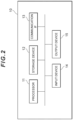
- FIG. 2 is a diagram showing an example of a hardware configuration of the data generation apparatus 10.
- the data generation apparatus 10 has a processor 11, such as a CPU (Central Processing Unit) or a GPU (Graphical processing unit), a storage device 12, such as a memory, an HDD (Hard Disk Drive), and/or an SSD (Solid State Drive), a communication IF (Interface) 13 which performs wired or wireless communication, an input device 14 which receives an input manipulation, and an output device 15 which outputs information.
- the input device 14 is, for example, a keyboard, a touch panel, a mouse, and/or a microphone.
- the output device 15 is, for example, a display, a touch panel, and/or a speaker.
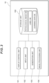
- FIG. 3 is a diagram showing an example of a functional block configuration of the data generation apparatus 10.
- the data generation apparatus 10 includes a storage unit 100, a display control unit 101, an input unit 102, a generation unit 103, and an image processing unit 104.
- the storage unit 100 can be implemented using the storage device 12 that the data generation apparatus 10 includes.
- the display control unit 101, the input unit 102, the generation unit 103, and the image processing unit 104 can be implemented through execution of a program stored in the storage device 12 by the processor 11 of the data generation apparatus 10.
- the program can be stored in a storage medium.
- the storage medium storing the program may be a computer readable non-transitory storage medium (non-transitory computer readable medium).
- the non-transitory storage medium is not particularly limited and may be, for example, a storage medium, such as a USB memory or a CD-ROM.
- the storage unit 100 stores a pathological image DB (image DB) storing one or more pathological images (images) used to generate learning data, a label DB storing a label given to a partial image by a user, and a learning data DB storing generated learning data.
- image DB pathological image DB
- label DB storing a label given to a partial image by a user
- learning data DB storing generated learning data.
- the display control unit 101 displays various types of screens according to the present embodiment on the output device 15, such as a display, another information processing apparatus that communicates with the data generation apparatus 10, or the like.
- the display control unit 101 displays a screen in which borders of partial images are superimposed on a pathological image (image).
- the input unit 102 receives various types of inputs from a user.
- the input unit 102 also receives input of a label to be given to each of a plurality of partial images from the user via the input device 14.
- the input unit 102 stores a label given to each partial image in the label DB.
- the input unit 102 may store, for example, a partial image ID for unique identification of each partial image and the label given to the corresponding partial image in the label DB in association with each other.
- Label input may be performed by, for example, selecting a partial image, for which a label is to be input, from among partial images displayed on a screen and receiving designation of the label to be given to the partial image.
- the input unit 102 may receive input of information on a pathology type corresponding to the plurality of pathological images (the type of a pathology common to the plurality of pathological images and an image type corresponding to the plurality of images).
- the generation unit 103 generates learning data for causing a learning model to learn by associating each of a plurality of partial images with the label given to the corresponding partial image of the plurality of partial images by the input unit 102. For example, the generation unit 103 acquires a partial image ID and a label from the label DB and extracts image data of a partial image corresponding to the partial image ID from among pathological images (images) stored in the pathological image DB (image DB). The generation unit 103 then generates learning data by combining the extracted image data of the partial image and the label corresponding to the partial image ID.
- the image processing unit 104 changes colors of a plurality of pathological images (a plurality of images) in accordance with a color change method determined for a pathology type (image type) input to the input unit 102.
- a method that changes an RGB value of each pixel in the plurality of pathological images (the plurality of images) into a standardized value and a method that randomly changes the RGB value of each pixel in the plurality of pathological images (the plurality of images) may be included in the change method.
- Figure 4 is a flowchart showing an example of procedures to be performed by the data generation apparatus 10.
- the input unit 102 receives input of a pathological image used to generate learning data from a user and stores the input pathological image in the pathological image DB (S10).
- staining is usually performed. Examples of a method of the staining include hematoxylin and eosin stain, PAS stain, Pappenheim stain, alcian blue stain, Papanicolaou stain, Azan stain, Elastica-van Gieson method, and Elastica-Masson stain.
- the user inputs pathological images, pathology types of which are the same. The following description is based on the assumption that a plurality of pathological images are input by the user.
- the input unit 102 receives input of information on a pathology type from the user for the plurality of pathological images input in the procedure in step S10 (S11).
- a pathology type which can be input may be, for example, either "tumor” or "hypermutation.” If each of the plurality of pathological images is a tumor image, the user inputs "tumor” as the pathology type. If each of the plurality of pathological images is a hypermutation image, the user inputs "hypermutation" as the pathology type.
- the image processing unit 104 changes colors of the plurality of pathological images in accordance with a color change method corresponding to the pathology type input in the procedure in step S11 (S12). For example, if the pathology type is "tumor," the color change method may be changing an RGB value of each pixel in the plurality of pathological images to a standardized value.
- the image processing unit 104 calculates a mean value and a standard deviation of R (Red) values, a mean value and a standard deviation of G (Green) values, and a mean value and a standard deviation of B (Blue) values for all pixels in the plurality of pathological images.
- the image processing unit 104 then standardizes the respective R values of all the pixels in the plurality of pathological images, using the mean value and the standard deviation of the R values.
- the color change method may be a method that shifts the RGB value of each pixel in the plurality of pathological images in a manner randomly selected for each pathological image.
- the image processing unit 104 randomly determines a number, by which an RGB value is to be shifted, for each pathological image and shifts an R value, a G value, and a B value by the determined value. For example, if the image processing unit 104 determines a number, by which an RGB value is to be shifted, to be "5" for a first pathological image, the image processing unit 104 adds 5 to an R value, a G value, and a B value of each pixel included in the pathological image.
- the image processing unit 104 determines a number, by which an RGB value is to be shifted, to be "-2" for a second pathological image, the image processing unit 104 adds -2 to an R value, a G value, and a B value of each pixel included in the pathological image.
- the image processing unit 104 repeats similar processing for all the pathological images. This makes it possible to cause the tones of the plurality of pathological images to vary.
- the display control unit 101 selects one pathological image from among the plurality of input pathological images and displays a screen in which borders of partial images are superimposed on the selected pathological image (S13).
- the input unit 102 then receives input of a label to be given for each partial image (S14). If the plurality of input pathological images are tumor images, a label which the user is to give to each partial image is either a label indicating that the partial image is a tumor image or a label indicating that the partial image is not a tumor image.
- a label which the user is to give to each partial image is either a label indicating that the partial image is a hypermutation image or a label indicating that the partial image is not a hypermutation image.
- the input unit 102 stores each received label in the label DB in association with a partial image ID. If label input is not complete for the partial images (NO in S15), the data generation apparatus 10 repeats the procedure in step S14. If label input is complete for the partial images (YES in S15), the generation unit 103 generates learning data by associating image data of each partial image, for which labeling is complete, with a given label (S16). The determination as to whether label input is complete may be made on the basis of whether a press of a predetermined button (e.g., a button to start generation of learning data) on the screen is detected by the input unit 102. Alternatively, the determination may be made on the basis of whether labels are given to a predetermined number of partial images.
- a predetermined button e.g., a button to start generation of learning data
- label giving is complete if labels are given to a predetermined number of partial images, and if a ratio between labels given to partial images(a ratio of respective label types) falls within a predetermined range (e.g., a ratio between labels indicating tumor images and labels indicating non-tumor images is approximately 1:4).
- the generation unit 103 may store the generated learning data in the learning data DB while the generated learning data are sorted into folders for different labels.
- the generation unit 103 may store image data of a partial image given a tumor-containing label and image data of a partial image given a tumor-free label in different folders.
- a partial image, a tissue-free portion of which accounts for a predetermined percentage or higher, may be excluded from learning data.
- the input unit 102 may reject input of a label for a partial image, a portion in a specific color (e.g., a white portion) of which accounts for the predetermined percentage or higher, among a plurality of partial images in each pathological image in the procedure in step S14.
- the generation unit 103 may exclude a partial image, for which label input is not received by the input unit 102, among a plurality of partial images in learning data to be generated in the procedure in step S16. This makes it possible to inhibit learning data inappropriate for learning by a learning model from being generated.
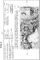
- Figure 5 is a view showing an example of a screen where labeling is to be performed.
- Figure 5 shows an example in a case where a pathological image is an image containing a tumor cell.
- a selection menu M10 is a menu to designate the type of pathological image input by a user.
- a selection menu M11 is a menu to designate a pathological image to be displayed on a screen in a case where a plurality of pathological images are input.
- the example in Figure 5 shows that 40 tumor-cell-related pathological images are input and that a third pathological image is currently displayed.
- a display area W10 in Figure 5 grid-like borders are superimposed and displayed on an enlarged image of a part of a pathological image.
- one region surrounded by borders corresponds to one partial image.
- an image of the whole pathological image and a display frame V11 indicating a region of the pathological image which is displayed on an enlarged scale in the display region W10 are displayed.
- the position or the size of the display frame V11 may be arbitrarily changed by, for example, a mouse manipulation. If the input unit 102 receives change of the position or the size of the display frame V11, the display control unit 101 changes a pathological image to be displayed on an enlarged scale in the display region W10 in accordance with the changed position and size of the display frame V11.
- the size (vertical and horizontal pixel counts) of a partial image is defined in advance in accordance with a learning model as a learning object, a user may be disallowed to arbitrarily change the size.
- the example in Figure 5 shows that the size of a partial image is 300 pixels in the vertical direction by 300 pixels in the horizontal direction.
- a position of the display frame T10 can be arbitrarily changed by selecting, by a user, a partial image for which the user desires to input a label.
- the display of the display frame T10 allows the user to recognize at which position and to which partial image the user is trying to give a label.
- the display control unit 101 may display, on a screen where labeling is to be performed, both information indicating a ratio of respective labels to be given to each of a plurality of partial images, the ratio being a target value, and information indicating an actual value of a ratio of respective labels that have been given to a plurality of partial images.
- the display control unit 101 may display, on the screen where labeling is to be performed, both a target value for the number of partial images to be labeled and information indicating an actual value of the number of partial images to which labels have been given. For example, assume that the condition that, if 2,000 images are learned as learning data, recognition accuracy of a learned model increase is present. In the example in Figure 5 , the criterial description "The target number for the number of tiles to be labeled is 2,000" is displayed in terms of a target value in the memo display region A10. This shows that a user who gives labels desirably gives labels to 2,000 partial images. An actual value of the number of partial images to which labels have already been given is displayed in a display region N11. Thus, the user can recognize that the user needs to give labels to 1,000 more partial images.
- a plurality of partial images may be images generated by dividing a pathological image at a predetermined interval in a rightward direction and in a downward direction (e.g., at the interval of 300 pixels in the rightward direction and at the interval of 300 pixels in the downward direction) from a point (e.g., a pixel on the upper left) serving as a reference in the pathological image.
- the plurality of partial images are not limited to the above-described ones and may be images generated by dividing the pathological image at a predetermined interval in a left-right direction and in an up-down direction (e.g., at the interval of 300 pixels in the right-left direction and at the interval of 300 pixels in the up-down direction) from a point shifted by a predetermined distance from the point serving as the reference in the pathological image.
- the plurality of partial images may be images generated by dividing the pathological image at the predetermined interval in the rightward direction and in the downward direction with respect to a point (pixel) shifted in the rightward direction and/or the downward direction by the predetermined distance from the point (an image on the upper left) serving as the reference in the pathological image.
- An offset value designation region M12 is a region for designating by how many pixels the point serving as the reference in the pathological image is to be shifted in the rightward direction.
- An offset value designation region M13 is a region for designating by how many pixels the point serving as the reference in the pathological image is to be shifted in the downward direction.
- a partial image P1 indicates a partial image located uppermost and leftmost in a pathological image in a case where partial images are generated by dividing the pathological image at a predetermined interval in a rightward direction and in a downward direction with respect to the upper left of the pathological image, and a partial image P6 indicates a partial image to the immediate right of the partial image P1.
- 50 pixels and 0 pixels are input in the offset value designation regions M12 and M13, respectively, in Figure 5 .
- a partial image P2 is generated with respect to a point shifted by 50 pixels rightward from the upper left of the pathological image.
- the data generation apparatus 10 is configured to divide an image into a plurality of partial images and display the plurality of partial images, and receive input of a label from a user for each partial image. This allows easier generation of image-related learning data.
- the data generation apparatus 10 is also configured to change color-related pixel values of a plurality of pathological images in accordance with a pixel value change method determined for an image type corresponding to the plurality of images. This makes it possible to change tones of a plurality of images to more appropriate tones suitable for a learning model to learn in accordance with an image type and generate a learned model with higher recognition accuracy.
- the data generation apparatus 10 is also configured to display a target value and an actual value for a ratio between types of labels to be given to respective partial images. Since a user can give a label to each partial image such that the actual value approaches the target value, it is possible to efficiently generate learning data for generation of a learned model with higher recognition accuracy.
- the data generation apparatus 10 is capable of dividing an image into partial images with respect to an arbitrary point (pixel) on the image at the time of division of the image into partial images. This allows a user to generate a large number of pieces of learning data even in a case where the number of input images is small by performing labeling and then repeating the work of shifting a reference point at the time of division of an image into partial images and performing labeling again.
Landscapes
- Engineering & Computer Science (AREA)
- Theoretical Computer Science (AREA)
- Physics & Mathematics (AREA)
- General Physics & Mathematics (AREA)
- Computer Vision & Pattern Recognition (AREA)
- Health & Medical Sciences (AREA)
- General Health & Medical Sciences (AREA)
- Medical Informatics (AREA)
- Radiology & Medical Imaging (AREA)
- Quality & Reliability (AREA)
- Nuclear Medicine, Radiotherapy & Molecular Imaging (AREA)
- Multimedia (AREA)
- Artificial Intelligence (AREA)
- Computing Systems (AREA)
- Databases & Information Systems (AREA)
- Evolutionary Computation (AREA)
- Software Systems (AREA)
- Image Analysis (AREA)
Applications Claiming Priority (2)
| Application Number | Priority Date | Filing Date | Title |
|---|---|---|---|
| JP2020068413 | 2020-04-06 | ||
| PCT/JP2021/014494 WO2021206053A1 (fr) | 2020-04-06 | 2021-04-05 | Dispositif de génération de données, procédé de génération de données et programme |
Publications (2)
| Publication Number | Publication Date |
|---|---|
| EP4134909A1 true EP4134909A1 (fr) | 2023-02-15 |
| EP4134909A4 EP4134909A4 (fr) | 2024-02-21 |
Family
ID=78023254
Family Applications (1)
| Application Number | Title | Priority Date | Filing Date |
|---|---|---|---|
| EP21785651.7A Pending EP4134909A4 (fr) | 2020-04-06 | 2021-04-05 | Dispositif de génération de données, procédé de génération de données et programme |
Country Status (6)
| Country | Link |
|---|---|
| US (1) | US12387339B2 (fr) |
| EP (1) | EP4134909A4 (fr) |
| JP (2) | JP7236202B2 (fr) |
| KR (1) | KR20220164755A (fr) |
| CN (1) | CN115380307A (fr) |
| WO (1) | WO2021206053A1 (fr) |
Families Citing this family (2)
| Publication number | Priority date | Publication date | Assignee | Title |
|---|---|---|---|---|
| WO2024247990A1 (fr) * | 2023-05-31 | 2024-12-05 | デンカ株式会社 | Programme, procédé de génération et système |
| JPWO2024247991A1 (fr) | 2023-05-31 | 2024-12-05 |
Family Cites Families (24)
| Publication number | Priority date | Publication date | Assignee | Title |
|---|---|---|---|---|
| US5222206A (en) * | 1989-06-08 | 1993-06-22 | Computer Design, Inc. | Image color modification in a computer-aided design system |
| JP3720538B2 (ja) * | 1997-07-15 | 2005-11-30 | キヤノン株式会社 | 画像検索装置及び方法 |
| JP2005185560A (ja) * | 2003-12-25 | 2005-07-14 | Konica Minolta Medical & Graphic Inc | 医用画像処理装置及び医用画像処理システム |
| US9575994B2 (en) * | 2011-02-11 | 2017-02-21 | Siemens Aktiengesellschaft | Methods and devices for data retrieval |
| JP6067264B2 (ja) * | 2012-07-17 | 2017-01-25 | Hoya株式会社 | 画像処理装置及び内視鏡装置 |
| US9491318B2 (en) * | 2015-04-13 | 2016-11-08 | Kodak Alaris Inc. | Automatically generated visual annotated graphic legend |
| JP2017099721A (ja) * | 2015-12-02 | 2017-06-08 | パナソニックIpマネジメント株式会社 | 画像処理装置及び画像処理方法 |
| JP6702716B2 (ja) | 2015-12-21 | 2020-06-03 | キヤノン株式会社 | 画像処理装置、画像処理方法及びプログラム |
| JP6623851B2 (ja) * | 2016-03-08 | 2019-12-25 | 富士通株式会社 | 学習方法、情報処理装置および学習プログラム |
| US10572996B2 (en) | 2016-06-28 | 2020-02-25 | Contextvision Ab | Method and system for detecting pathological anomalies in a digital pathology image and method for annotating a tissue slide |
| CN106339591B (zh) * | 2016-08-25 | 2019-04-02 | 汤一平 | 一种基于深度卷积神经网络的预防乳腺癌自助健康云服务系统 |
| US10062039B1 (en) * | 2017-06-28 | 2018-08-28 | CS Disco, Inc. | Methods and apparatus for asynchronous and interactive machine learning using word embedding within text-based documents and multimodal documents |
| JP7027070B2 (ja) * | 2017-08-31 | 2022-03-01 | キヤノン株式会社 | 情報処理装置、情報処理方法、及びプログラム |
| CN111727371B (zh) | 2018-02-15 | 2022-11-04 | 国立大学法人新潟大学 | 超突变型癌的判别系统、程序及方法 |
| JP6945474B2 (ja) * | 2018-02-28 | 2021-10-06 | 富士フイルム株式会社 | 学習用データ作成支援装置、学習用データ作成支援方法、および学習用データ作成支援プログラム |
| JP7036401B2 (ja) * | 2018-04-27 | 2022-03-15 | Awl株式会社 | 学習用サーバ、不足学習用画像収集支援システム、及び不足学習用画像推定プログラム |
| JP7235272B2 (ja) * | 2018-05-16 | 2023-03-08 | 株式会社アドダイス | 画像処理装置及び検査システム |
| EP3815040A4 (fr) | 2018-05-21 | 2022-03-02 | Corista LLC | Traitement d'images plein champ multi-échantillon dans une pathologie numérique par enregistrement multi-résolution et apprentissage automatique |
| EP3826544B1 (fr) * | 2018-07-26 | 2024-06-05 | Koninklijke Philips N.V. | Système à ultrasons doté d'un réseau neuronal artificiel pour imagerie hépatique guidée |
| JP6952660B2 (ja) * | 2018-08-28 | 2021-10-20 | 株式会社東芝 | 更新支援装置、更新支援方法およびプログラム |
| US10631828B1 (en) * | 2018-12-11 | 2020-04-28 | Eko.Ai Pte. Ltd. | Automatic clinical workflow that recognizes and analyzes 2D and doppler modality echocardiogram images for automated cardiac measurements and the diagnosis, prediction and prognosis of heart disease |
| WO2020142566A1 (fr) * | 2018-12-31 | 2020-07-09 | Tempus Labs, Inc. | Segmentation d'images de tissu par intelligence artificielle |
| CN110503151B (zh) * | 2019-08-26 | 2020-11-03 | 北京推想科技有限公司 | 一种影像的处理方法和系统 |
| WO2021141976A1 (fr) * | 2020-01-06 | 2021-07-15 | Translational Imaging Innovations, Inc. | Procédés, systèmes et produits programmes d'ordinateur permettant de classifier des données d'images |
-
2021
- 2021-04-05 CN CN202180024507.9A patent/CN115380307A/zh active Pending
- 2021-04-05 WO PCT/JP2021/014494 patent/WO2021206053A1/fr not_active Ceased
- 2021-04-05 KR KR1020227038232A patent/KR20220164755A/ko active Pending
- 2021-04-05 JP JP2022514063A patent/JP7236202B2/ja active Active
- 2021-04-05 EP EP21785651.7A patent/EP4134909A4/fr active Pending
- 2021-04-05 US US17/917,542 patent/US12387339B2/en active Active
-
2023
- 2023-02-22 JP JP2023025993A patent/JP7642002B2/ja active Active
Also Published As
| Publication number | Publication date |
|---|---|
| JP2023058726A (ja) | 2023-04-25 |
| JP7642002B2 (ja) | 2025-03-07 |
| EP4134909A4 (fr) | 2024-02-21 |
| CN115380307A (zh) | 2022-11-22 |
| WO2021206053A1 (fr) | 2021-10-14 |
| US20230148243A1 (en) | 2023-05-11 |
| KR20220164755A (ko) | 2022-12-13 |
| JPWO2021206053A1 (fr) | 2021-10-14 |
| JP7236202B2 (ja) | 2023-03-09 |
| US12387339B2 (en) | 2025-08-12 |
Similar Documents
| Publication | Publication Date | Title |
|---|---|---|
| KR102347336B1 (ko) | 응시점 판단 방법 및 장치, 전자 기기 및 컴퓨터 저장 매체 | |
| CN104584069B (zh) | 信息处理装置、信息处理方法以及程序 | |
| US10692133B2 (en) | Color estimation device, color estimation method, and color estimation program | |
| US20150278710A1 (en) | Machine learning apparatus, machine learning method, and non-transitory computer-readable recording medium | |
| US12387339B2 (en) | Data generation apparatus, data generation method, and program | |
| CN110390327B (zh) | 前景提取方法、装置、计算机设备及存储介质 | |
| KR20230095801A (ko) | 인공지능 기반의 병리영상 암 병변 맞춤형 위치 표시 방법 및 시스템 | |
| US20150356731A1 (en) | Image processing device, storage medium, and image processing method | |
| JP6546385B2 (ja) | 画像処理装置及びその制御方法、プログラム | |
| JP2013210793A (ja) | Ar表示最適化のためのシステム、方法、およびプログラム | |
| JP7045103B1 (ja) | データ拡張装置、データ拡張システム、及びデータ拡張プログラム | |
| JP7387346B2 (ja) | 画像処理装置、その制御方法、プログラム | |
| JP2022185872A (ja) | 画像処理装置、画像処理方法、撮像装置 | |
| JP2004246739A (ja) | ドキュメント処理装置 | |
| JP2021197599A (ja) | 画像処理装置、画像処理方法及びプログラム | |
| JP2025065748A (ja) | 画像処理装置、画像処理方法、及びプログラム | |
| US10802770B2 (en) | Dividing a spanning region of adjacent sub-images to generate print data | |
| TWI845373B (zh) | 多重螢光組織影像分析方法及其系統 | |
| US20210124932A1 (en) | Image processing method, image processing apparatus, and storage medium | |
| JP2006023798A (ja) | 画像データ処理装置および方法,ならびに画像データ処理プログラム | |
| CN108694031B (zh) | 一种用于三维显示图片的识别方法及装置 | |
| CN110572626B (zh) | 一种图像处理方法及设备 | |
| JP2016062269A (ja) | アルゴリズム生成装置、アルゴリズム生成方法及びアルゴリズム生成用コンピュータプログラム | |
| US20230215050A1 (en) | Information processing apparatus, method, and storage medium to generate a color-difference map | |
| US20210158588A1 (en) | Data-creation assistance apparatus, data-creation assistance method, and data-creation assistance program |
Legal Events
| Date | Code | Title | Description |
|---|---|---|---|
| STAA | Information on the status of an ep patent application or granted ep patent |
Free format text: STATUS: THE INTERNATIONAL PUBLICATION HAS BEEN MADE |
|
| PUAI | Public reference made under article 153(3) epc to a published international application that has entered the european phase |
Free format text: ORIGINAL CODE: 0009012 |
|
| STAA | Information on the status of an ep patent application or granted ep patent |
Free format text: STATUS: REQUEST FOR EXAMINATION WAS MADE |
|
| 17P | Request for examination filed |
Effective date: 20221102 |
|
| AK | Designated contracting states |
Kind code of ref document: A1 Designated state(s): AL AT BE BG CH CY CZ DE DK EE ES FI FR GB GR HR HU IE IS IT LI LT LU LV MC MK MT NL NO PL PT RO RS SE SI SK SM TR |
|
| DAV | Request for validation of the european patent (deleted) | ||
| DAX | Request for extension of the european patent (deleted) | ||
| A4 | Supplementary search report drawn up and despatched |
Effective date: 20240124 |
|
| RIC1 | Information provided on ipc code assigned before grant |
Ipc: G06T 7/00 20170101AFI20240118BHEP |
|
| STAA | Information on the status of an ep patent application or granted ep patent |
Free format text: STATUS: EXAMINATION IS IN PROGRESS |
|
| 17Q | First examination report despatched |
Effective date: 20250528 |
|
| GRAP | Despatch of communication of intention to grant a patent |
Free format text: ORIGINAL CODE: EPIDOSNIGR1 |
|
| STAA | Information on the status of an ep patent application or granted ep patent |
Free format text: STATUS: GRANT OF PATENT IS INTENDED |
|
| INTG | Intention to grant announced |
Effective date: 20251212 |
|
| GRAJ | Information related to disapproval of communication of intention to grant by the applicant or resumption of examination proceedings by the epo deleted |
Free format text: ORIGINAL CODE: EPIDOSDIGR1 |
|
| STAA | Information on the status of an ep patent application or granted ep patent |
Free format text: STATUS: EXAMINATION IS IN PROGRESS |
|
| GRAP | Despatch of communication of intention to grant a patent |
Free format text: ORIGINAL CODE: EPIDOSNIGR1 |
|
| STAA | Information on the status of an ep patent application or granted ep patent |
Free format text: STATUS: GRANT OF PATENT IS INTENDED |
|
| INTC | Intention to grant announced (deleted) | ||
| INTG | Intention to grant announced |
Effective date: 20260306 |