EP4135077A1 - Festoxid-brennstoffzelle; die eine laminierte anoden- und elektrolytschicht aufweist, und verfahren zum herstellen davon - Google Patents
Festoxid-brennstoffzelle; die eine laminierte anoden- und elektrolytschicht aufweist, und verfahren zum herstellen davon Download PDFInfo
- Publication number
- EP4135077A1 EP4135077A1 EP22178303.8A EP22178303A EP4135077A1 EP 4135077 A1 EP4135077 A1 EP 4135077A1 EP 22178303 A EP22178303 A EP 22178303A EP 4135077 A1 EP4135077 A1 EP 4135077A1
- Authority
- EP
- European Patent Office
- Prior art keywords
- layer
- anode
- electrolyte
- ceramic
- sofc
- Prior art date
- Legal status (The legal status is an assumption and is not a legal conclusion. Google has not performed a legal analysis and makes no representation as to the accuracy of the status listed.)
- Pending
Links
Images


Classifications
-
- H—ELECTRICITY
- H01—ELECTRIC ELEMENTS
- H01M—PROCESSES OR MEANS, e.g. BATTERIES, FOR THE DIRECT CONVERSION OF CHEMICAL ENERGY INTO ELECTRICAL ENERGY
- H01M8/00—Fuel cells; Manufacture thereof
- H01M8/10—Fuel cells with solid electrolytes
- H01M8/12—Fuel cells with solid electrolytes operating at high temperature, e.g. with stabilised ZrO2 electrolyte
- H01M8/124—Fuel cells with solid electrolytes operating at high temperature, e.g. with stabilised ZrO2 electrolyte characterised by the process of manufacturing or by the material of the electrolyte
- H01M8/1246—Fuel cells with solid electrolytes operating at high temperature, e.g. with stabilised ZrO2 electrolyte characterised by the process of manufacturing or by the material of the electrolyte the electrolyte consisting of oxides
-
- H—ELECTRICITY
- H01—ELECTRIC ELEMENTS
- H01M—PROCESSES OR MEANS, e.g. BATTERIES, FOR THE DIRECT CONVERSION OF CHEMICAL ENERGY INTO ELECTRICAL ENERGY
- H01M4/00—Electrodes
- H01M4/86—Inert electrodes with catalytic activity, e.g. for fuel cells
- H01M4/8636—Inert electrodes with catalytic activity, e.g. for fuel cells with a gradient in another property than porosity
-
- H—ELECTRICITY
- H01—ELECTRIC ELEMENTS
- H01M—PROCESSES OR MEANS, e.g. BATTERIES, FOR THE DIRECT CONVERSION OF CHEMICAL ENERGY INTO ELECTRICAL ENERGY
- H01M4/00—Electrodes
- H01M4/86—Inert electrodes with catalytic activity, e.g. for fuel cells
- H01M4/8647—Inert electrodes with catalytic activity, e.g. for fuel cells consisting of more than one material, e.g. consisting of composites
- H01M4/8657—Inert electrodes with catalytic activity, e.g. for fuel cells consisting of more than one material, e.g. consisting of composites layered
-
- H—ELECTRICITY
- H01—ELECTRIC ELEMENTS
- H01M—PROCESSES OR MEANS, e.g. BATTERIES, FOR THE DIRECT CONVERSION OF CHEMICAL ENERGY INTO ELECTRICAL ENERGY
- H01M4/00—Electrodes
- H01M4/86—Inert electrodes with catalytic activity, e.g. for fuel cells
- H01M4/88—Processes of manufacture
- H01M4/8878—Treatment steps after deposition of the catalytic active composition or after shaping of the electrode being free-standing body
- H01M4/8882—Heat treatment, e.g. drying, baking
- H01M4/8885—Sintering or firing
-
- H—ELECTRICITY
- H01—ELECTRIC ELEMENTS
- H01M—PROCESSES OR MEANS, e.g. BATTERIES, FOR THE DIRECT CONVERSION OF CHEMICAL ENERGY INTO ELECTRICAL ENERGY
- H01M4/00—Electrodes
- H01M4/86—Inert electrodes with catalytic activity, e.g. for fuel cells
- H01M4/90—Selection of catalytic material
- H01M4/9016—Oxides, hydroxides or oxygenated metallic salts
- H01M4/9025—Oxides specially used in fuel cell operating at high temperature, e.g. SOFC
-
- H—ELECTRICITY
- H01—ELECTRIC ELEMENTS
- H01M—PROCESSES OR MEANS, e.g. BATTERIES, FOR THE DIRECT CONVERSION OF CHEMICAL ENERGY INTO ELECTRICAL ENERGY
- H01M4/00—Electrodes
- H01M4/86—Inert electrodes with catalytic activity, e.g. for fuel cells
- H01M4/90—Selection of catalytic material
- H01M4/9041—Metals or alloys
- H01M4/905—Metals or alloys specially used in fuel cell operating at high temperature, e.g. SOFC
- H01M4/9066—Metals or alloys specially used in fuel cell operating at high temperature, e.g. SOFC of metal-ceramic composites or mixtures, e.g. cermets
-
- H—ELECTRICITY
- H01—ELECTRIC ELEMENTS
- H01M—PROCESSES OR MEANS, e.g. BATTERIES, FOR THE DIRECT CONVERSION OF CHEMICAL ENERGY INTO ELECTRICAL ENERGY
- H01M8/00—Fuel cells; Manufacture thereof
- H01M8/10—Fuel cells with solid electrolytes
- H01M8/12—Fuel cells with solid electrolytes operating at high temperature, e.g. with stabilised ZrO2 electrolyte
- H01M8/1213—Fuel cells with solid electrolytes operating at high temperature, e.g. with stabilised ZrO2 electrolyte characterised by the electrode/electrolyte combination or the supporting material
-
- H—ELECTRICITY
- H01—ELECTRIC ELEMENTS
- H01M—PROCESSES OR MEANS, e.g. BATTERIES, FOR THE DIRECT CONVERSION OF CHEMICAL ENERGY INTO ELECTRICAL ENERGY
- H01M8/00—Fuel cells; Manufacture thereof
- H01M8/10—Fuel cells with solid electrolytes
- H01M8/12—Fuel cells with solid electrolytes operating at high temperature, e.g. with stabilised ZrO2 electrolyte
- H01M2008/1293—Fuel cells with solid oxide electrolytes
-
- H—ELECTRICITY
- H01—ELECTRIC ELEMENTS
- H01M—PROCESSES OR MEANS, e.g. BATTERIES, FOR THE DIRECT CONVERSION OF CHEMICAL ENERGY INTO ELECTRICAL ENERGY
- H01M2300/00—Electrolytes
- H01M2300/0017—Non-aqueous electrolytes
- H01M2300/0065—Solid electrolytes
- H01M2300/0068—Solid electrolytes inorganic
- H01M2300/0071—Oxides
- H01M2300/0074—Ion conductive at high temperature
-
- H—ELECTRICITY
- H01—ELECTRIC ELEMENTS
- H01M—PROCESSES OR MEANS, e.g. BATTERIES, FOR THE DIRECT CONVERSION OF CHEMICAL ENERGY INTO ELECTRICAL ENERGY
- H01M4/00—Electrodes
- H01M4/86—Inert electrodes with catalytic activity, e.g. for fuel cells
- H01M4/88—Processes of manufacture
- H01M4/8803—Supports for the deposition of the catalytic active composition
- H01M4/881—Electrolytic membranes
-
- H—ELECTRICITY
- H01—ELECTRIC ELEMENTS
- H01M—PROCESSES OR MEANS, e.g. BATTERIES, FOR THE DIRECT CONVERSION OF CHEMICAL ENERGY INTO ELECTRICAL ENERGY
- H01M4/00—Electrodes
- H01M4/86—Inert electrodes with catalytic activity, e.g. for fuel cells
- H01M4/88—Processes of manufacture
- H01M4/8825—Methods for deposition of the catalytic active composition
- H01M4/8828—Coating with slurry or ink
- H01M4/8832—Ink jet printing
-
- H—ELECTRICITY
- H01—ELECTRIC ELEMENTS
- H01M—PROCESSES OR MEANS, e.g. BATTERIES, FOR THE DIRECT CONVERSION OF CHEMICAL ENERGY INTO ELECTRICAL ENERGY
- H01M4/00—Electrodes
- H01M4/86—Inert electrodes with catalytic activity, e.g. for fuel cells
- H01M4/88—Processes of manufacture
- H01M4/8825—Methods for deposition of the catalytic active composition
- H01M4/8828—Coating with slurry or ink
- H01M4/8835—Screen printing
-
- H—ELECTRICITY
- H01—ELECTRIC ELEMENTS
- H01M—PROCESSES OR MEANS, e.g. BATTERIES, FOR THE DIRECT CONVERSION OF CHEMICAL ENERGY INTO ELECTRICAL ENERGY
- H01M4/00—Electrodes
- H01M4/86—Inert electrodes with catalytic activity, e.g. for fuel cells
- H01M4/88—Processes of manufacture
- H01M4/8825—Methods for deposition of the catalytic active composition
- H01M4/8857—Casting, e.g. tape casting, vacuum slip casting
-
- H—ELECTRICITY
- H01—ELECTRIC ELEMENTS
- H01M—PROCESSES OR MEANS, e.g. BATTERIES, FOR THE DIRECT CONVERSION OF CHEMICAL ENERGY INTO ELECTRICAL ENERGY
- H01M4/00—Electrodes
- H01M4/86—Inert electrodes with catalytic activity, e.g. for fuel cells
- H01M4/88—Processes of manufacture
- H01M4/8875—Methods for shaping the electrode into free-standing bodies, like sheets, films or grids, e.g. moulding, hot-pressing, casting without support, extrusion without support
-
- H—ELECTRICITY
- H01—ELECTRIC ELEMENTS
- H01M—PROCESSES OR MEANS, e.g. BATTERIES, FOR THE DIRECT CONVERSION OF CHEMICAL ENERGY INTO ELECTRICAL ENERGY
- H01M4/00—Electrodes
- H01M4/86—Inert electrodes with catalytic activity, e.g. for fuel cells
- H01M4/88—Processes of manufacture
- H01M4/8878—Treatment steps after deposition of the catalytic active composition or after shaping of the electrode being free-standing body
- H01M4/8882—Heat treatment, e.g. drying, baking
- H01M4/8885—Sintering or firing
- H01M4/8889—Cosintering or cofiring of a catalytic active layer with another type of layer
-
- Y—GENERAL TAGGING OF NEW TECHNOLOGICAL DEVELOPMENTS; GENERAL TAGGING OF CROSS-SECTIONAL TECHNOLOGIES SPANNING OVER SEVERAL SECTIONS OF THE IPC; TECHNICAL SUBJECTS COVERED BY FORMER USPC CROSS-REFERENCE ART COLLECTIONS [XRACs] AND DIGESTS
- Y02—TECHNOLOGIES OR APPLICATIONS FOR MITIGATION OR ADAPTATION AGAINST CLIMATE CHANGE
- Y02E—REDUCTION OF GREENHOUSE GAS [GHG] EMISSIONS, RELATED TO ENERGY GENERATION, TRANSMISSION OR DISTRIBUTION
- Y02E60/00—Enabling technologies; Technologies with a potential or indirect contribution to GHG emissions mitigation
- Y02E60/30—Hydrogen technology
- Y02E60/50—Fuel cells
-
- Y—GENERAL TAGGING OF NEW TECHNOLOGICAL DEVELOPMENTS; GENERAL TAGGING OF CROSS-SECTIONAL TECHNOLOGIES SPANNING OVER SEVERAL SECTIONS OF THE IPC; TECHNICAL SUBJECTS COVERED BY FORMER USPC CROSS-REFERENCE ART COLLECTIONS [XRACs] AND DIGESTS
- Y02—TECHNOLOGIES OR APPLICATIONS FOR MITIGATION OR ADAPTATION AGAINST CLIMATE CHANGE
- Y02P—CLIMATE CHANGE MITIGATION TECHNOLOGIES IN THE PRODUCTION OR PROCESSING OF GOODS
- Y02P70/00—Climate change mitigation technologies in the production process for final industrial or consumer products
- Y02P70/50—Manufacturing or production processes characterised by the final manufactured product
Definitions
- the embodiments of the present invention are generally directed to solid oxide fuel cells (SOFC) and methods of making thereof.
- SOFC solid oxide fuel cells
- an oxidizing flow is passed through the cathode side of the fuel cell, while a fuel flow is passed through the anode side of the fuel cell.
- the oxidizing flow is typically air, while the fuel flow can be a hydrocarbon fuel, such as methane, natural gas, propane, pentane, ethanol, or methanol.
- the fuel cell operating at a typical temperature between 750 °C and 950 °C, enables the transport of negatively charged oxygen ions from the cathode flow stream to the anode flow stream, where the ion combines with either free hydrogen or hydrogen in a hydrocarbon molecule to form water vapor and/or with carbon monoxide to form carbon dioxide.
- the excess electrons from the negatively charged ion are routed back to the cathode side of the fuel cell through an electrical circuit completed between anode and cathode, resulting in an electrical current flow through the circuit.
- a solid oxide fuel cell includes a ceramic electrolyte having a thickness of 100 microns or less, an anode laminated to a first side of the electrolyte, and a cathode located on a second side of the electrolyte opposite to the first side.
- a method of making a solid oxide fuel cell comprises separately forming a ceramic electrolyte precursor layer and at least one anode precursor layer without contacting each other, stacking the formed at least one anode precursor layer in contact with a first side of the ceramic electrolyte precursor layer, laminating the at least one anode precursor layer and the ceramic electrolyte precursor layer, and forming at least one cathode layer.
- the electrical resistivity of a SOFC may be decreased by reducing the thickness of the ceramic electrolyte.
- a thinner electrolyte is more prone to crack due to defects therein and/or stress imposed thereon.
- firing i.e., binder burnout and sintering
- a ceramic electrolyte layer causes stress on the ceramic electrolyte. If the electrolyte is relatively thin, then the firing may cause the ceramic electrolyte to crack.
- the electrically conductive phase in the anode is thermally cycled between the metal phase (e.g., nickel phase) and a metal oxide phase (e.g., nickel oxide phase) during respective thermal reduction and oxidation steps.
- the anode may be initially formed with a metal oxide phase and a ceramic phase, followed by a thermal reduction step in a reducing (e.g., hydrogen containing) ambient to convert the metal oxide phase into a metal phase.
- a reducing e.g., hydrogen containing
- the electrolyte precursor layer and one or more anode precursor layers are formed separately without contacting each other.
- the electrolyte precursor layer and one or more anode precursor layers are then stacked together and laminated into a half-SOFC by any suitable pressing method.
- an electrolyte precursor layer and one or more anode precursor layers may be formed separately by tape casting or another suitable ceramic or cermet precursor layer manufacturing process.
- the one or more anode precursor layers are then dried and placed in contact with each other and with a first side of the dried electrolyte precursor layer, and pressed together, such as by hot isostatic pressing or another suitable pressing method, to form a composite (e.g., a green composite).
- the composite is then sintered 1300 °C and 1400 °C to form the half-SOFC (i.e., a monolithic substrate for the cathode).
- the half-SOFC includes a monolithic structure containing one or more cermet anode layers contacting a first side of the ceramic electrolyte layer.
- the electrolyte Since the electrolyte is sintered together with the one or more anode layers during the same sintering step, the ceramic (i.e., sintered) electrolyte is not subjected to the stress of anode firing step. This reduces electrolyte cracking or breakage. Therefore, the electrolyte thickness may be decreased to reduce the electrical resistivity of the SOFC without significantly increasing electrolyte damage, such as cracking.
- the electrolyte may have a thickness of 100 microns or less, such as 5 to 100 microns, for example 5 to 25 microns or 50 to 100 microns.
- the porosity in the sintered half-SOFC may be controlled by selecting a desired volume fraction of organic materials (e.g., binder, dispersant, etc.) in the tape, by the control of the ceramic or cermet precursor particle size distribution in the specific tape, and/or by the addition of pore formers, such as fine particles or small spheres of a polymeric material, such as poly(methyl methacrylate) (PMMA), into the tape during the tape casting process.
- pore formers such as fine particles or small spheres of a polymeric material, such as poly(methyl methacrylate) (PMMA), into the tape during the tape casting process.
- PMMA poly(methyl methacrylate)
- one or more cathode layers are then formed on the second side of the ceramic electrolyte layer which is opposite from the first side of the ceramic electrolyte layer.
- the one or more cathode layers may be formed by an ink deposition method, such as screen printing, followed by firing the one or more cathode layers at a temperature of 950 °C to 1150 °C to form the cathode on the half-SOFC (i.e., the sintered monolithic substrate containing the laminated ceramic electrolyte and cermet anode). As a result, the full SOFC is formed.
- the one or more cathode layers are formed separately from the electrolyte using tape casting or another suitable method.
- the one or more cathode layers are then placed in contact with the second surface of the electrolyte precursor layer and pressed together by hot isostatic pressing or another suitable method. The pressing may occur while the electrolyte precursor layer is in contact with or not in contact with the one or more anode precursor layers.
- the one or more cathode layers are then sintered together with the electrolyte precursor layer and optionally together with the one or more anode precursor layers.
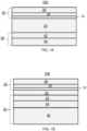
- FIG. 1A illustrates an exemplary electrolyte supported fuel cell 10A, according to various embodiments of the present invention.
- the fuel cell 10A may be a SOFC that contains an electrolyte 20 disposed between a cathode 30 (e.g., first electrode) and an anode 40 (e.g. second electrode).
- a cathode 30 e.g., first electrode
- an anode 40 e.g. second electrode
- the electrolyte 20 may have a thickness of less than 110 microns, such as 50 to 100 microns, for example 55 to 75 microns.
- the electrolyte 20 may comprise an ionically conductive ceramic, such as doped zirconia, doped ceria, and/or any other suitable ionically conductive ceramic oxide material.
- the electrolyte 20 may include yttria-stabilized zirconia (YSZ), yttria-ceria-stabilized zirconia (YCSZ), scandia-stabilized zirconia (SSZ), ytterbia-ceria-scandia-stabilized zirconia (YCSSZ), or blends thereof.
- scandia may be present in an amount equal to 9 to 11 mol %, such as 10 mol %
- ceria may present in amount greater than 0 and equal to or less than 3 mol %, for example 0.5 mol % to 2.5 mol %, such as 1 mol %
- ytterbia may be present in an amount greater than 0 and equal to or less than 2.5 mol %, for example 0.5 mol % to 2 mol %, such as 1 mol %, as disclosed in U.S. Pat. No. 8,580,456 , which is incorporated herein, by reference.
- yttria may be present in an amount equal to 8 to 10 mol %, and optionally ceria may be present in an amount equal to 0 to 3 mol %.
- the electrolyte may include samaria, gadolinia, or yttria-doped ceria.
- the cathode 30 may include an electrically conductive material, such as an electrically conductive perovskite material or metal.
- the cathode 30 may comprise one or more layers.
- the cathode 30 may include an optional cathode barrier layer 32 contacting the second side of the electrolyte 20.
- the cathode barrier layer 32 may comprise a doped ceria, such as samaria, gadolinia and/or praseodymia doped ceria.
- the cathode barrier layer 32 may comprise 10 to 20 mol % of Sm 2 O 3 , Gd 2 O 3 , and/or Pr 2 O 3 doped CeO 2 .
- the cathode barrier layer 32 may have a thickness of 5 to 10 microns and may have a porosity of 0 to 10%.
- the cathode barrier layer 32 allows the use of more reactive overlying cathode layer materials, such as (LaSr)(FeCo)-based perovskites that would otherwise react with the electrolyte 30 to form undesirable zirconates. Furthermore, the cathode barrier layer 32 acts as a diffusion barrier layer reducing or preventing further migration of Co and/or Fe from the overlying cathode layers into the electrolyte 20. The migration of Co and/or Fe into the electrolyte undesirably reduces the ionic conductivity of the electrolyte 20.
- the cathode 30 also includes a cathode functional layer 34.
- the cathode functional layer 34 may be thicker than the cathode barrier layer 32, and may have a thickness of 15 to 50 microns, such as 25 to 30 microns.
- the cathode functional layer 34 may have a larger porosity than the cathode barrier layer 32 and may include an electrically conductive material, such as an electrically conductive perovskite, such as lanthanum strontium manganite (LSM), lanthanum strontium cobaltite (La,Sr)CoO 3 ("LSCo"), lanthanum strontium cobalt ferrite (La,Sr)(Co,Fe)O 3 (LSCF), lanthanum strontium ferrite (LSF), lanthanum calcium manganite (LCM), lanthanum strontium manganese ferrite (LSMF), lanthanum strontium chromite (LSCr), etc., or a metal, such
- the cathode functional layer 34 may include an electrically conductive component and an ionically conductive component, as described in US Patent Number 10,249,883 , issued on April 2, 2019, incorporated herein by reference in its entirety.
- the ionically conductive component comprises a ceria-based ceramic component, such as at least one of samaria doped ceria (SDC), gadolinia doped ceria (GDC), or yttria doped ceria (YDC).
- the ceriabased ceramic component has a formula Ce (1-x) A x O 2 , wherein A comprises at least one of samarium (Sm), gadolinium (Gd), or yttria (Y), wherein x is in a range of around 0.1 to 0.4.
- the electrically conductive component comprises an electrically conductive ceramic, such as lanthanum strontium manganite (LSM), lanthanum calcium manganite (LCM), lanthanum strontium cobalt ferrite (LSCF), lanthanum strontium ferrite (LSF), lanthanum strontium manganese ferrite (LSMF) and lanthanum strontium chromite (LSCr), or lanthanum strontium cobaltite (LSCo).
- LSM lanthanum strontium manganite
- LCM lanthanum calcium manganite
- LSCF lanthanum strontium cobalt ferrite
- LSF lanthanum strontium ferrite
- LSCr lanthanum strontium manganese ferrite
- LSCr lanthanum strontium chromite
- LSCo lanthanum strontium cobaltite
- the cathode functional layer 34 may contain 10 to 90 wt%, such as 55-75
- the cathode 30 also includes an optional cathode contact layer 36.
- the cathode contact layer 36 may be thicker and more electrically conductive than the cathode functional layer 34.
- the cathode contact layer 36 may have a thickness of 40 to 100 microns, such as 50 to 60 microns.
- the cathode functional layer 34 may include an electrically conductive material, such as an electrically conductive perovskite, such as lanthanum strontium manganite (LSM), lanthanum strontium cobaltite (La,Sr)CoO 3 ("LSCo"), lanthanum strontium cobalt ferrite (La,Sr)(Co,Fe)O 3 (LSCF), lanthanum strontium ferrite (LSF), lanthanum calcium manganite (LCM), lanthanum strontium manganese ferrite (LSMF), lanthanum strontium chromite (LSCr), etc., or a metal, such as Pt.
- LSM electrically conductive perovskite
- LSM lanthanum strontium manganite
- LSCF lanthanum strontium cobalt ferrite
- LCF lanthanum strontium cobalt ferrite
- LCF lanthanum strontium
- the anode 40 may comprise one or more layers that include at least one cermet that includes a metallic phase and a ceramic phase.
- the metallic phase may include a metal catalyst and the ceramic phase may include one or more ceramic materials.
- the metallic phase may be very finely dispersed within the ceramic matrix of the ceramic phase, so as to limit damage that may occur if the metallic phase is oxidized.
- the metallic phase may have an average grain size less than 500 nanometers, such as from 100 to 400 nanometers.
- the ceramic phase of the anode 40 may comprise any suitable ionically conductive ceramic material, such as a doped ceria and/or a doped zirconia.
- the ceramic phase may include, but is not limited to gadolinia-doped ceria (GDC), samaria-doped ceria (SDC), praseodymia doped ceria (PDC), ytterbia-doped ceria (YDC), scandia-stabilized zirconia (SSZ), ytterbia-ceria-scandia-stabilized zirconia (YCSSZ), yttria stabilized zirconia (YSZ), or the like.
- GDC gadolinia-doped ceria
- SDC samaria-doped ceria
- PDC praseodymia doped ceria
- YDC ytterbia-doped ceria
- SSZ scandia
- the ceramic material may comprise a doped ceria, such as samaria, gadolinia and/or praseodymia doped ceria, for example 10 to 20 mol % of Sm 2 O 3 , Gd 2 O 3 , and/or Pr 2 O 3 doped CeO 2 .
- a doped ceria such as samaria, gadolinia and/or praseodymia doped ceria, for example 10 to 20 mol % of Sm 2 O 3 , Gd 2 O 3 , and/or Pr 2 O 3 doped CeO 2 .
- the metallic phase may include a metal catalyst such as nickel (Ni), which operates as an electron conductor.
- the metal catalyst may be in a metallic state or may be in an oxide state.
- the metal catalyst forms a metal oxide when it is in an oxidized state.
- the anode 40 may be annealed in a reducing atmosphere prior to and/or during operation of the fuel cell 10A, to reduce the metal catalyst to a metallic state.
- the metallic phase in its oxide state may include the metal catalyst and a dopant (i.e., alloying element).
- the metallic phase may be represented by formula D x Ni 1-x O, where D is a dopant (in any oxidation state) selected from Al, Ca, Ce, Cr, Fe, Mg, Mn, Nb, Pr, Ti, V, W, or Zr, any oxide thereof, or any combination thereof, as described in U.S. Patent 10,680,251, issued on June 9, 2020 , and incorporated herein by reference in its entirety.
- X may range from 0 to 1, such as 0.01 to 0.1
- y may range from 1 to 2.
- x may range from 0.01 to 0.04.
- x may be 0.02 and y may be either 1 or 2.
- the metallic phase may comprise from 1 to 10 atomic percent ("at%") of the metal oxide dopant and 99 to 90 at% of the metal catalyst.
- the metallic phase may comprise from 2 to 4 at% of the metal oxide dopant and 98 to 96 at% of the metal catalyst, as manufactured before being reduced.
- the anode 40 may include a metallic phase that includes NiO doped with MgO.
- the metallic phase may include Mg x Ni 1-x O, wherein x is within the ranges described above.
- the metallic phase is reduced by being exposed to a reducing ambient (e.g., fuel) at an elevated temperature (e.g., at a temperature ranging from 750-950°C).
- the reduced metallic phase may be represented by the formula D x M 1-x .
- the anode 40 may be an oxidation-tolerant electrode having a functionally graded configuration.
- the anode 40 may include a first layer 42 disposed on or over the first side of the electrolyte 20, and a second layer 44 disposed on the first layer 42.
- the first layer 42 may be disposed closer to the electrolyte 20 than the second layer 44.
- the first layer 42 may be configured to electrochemically oxidize a fuel.
- the second layer 44 may be configured for electron conduction and may operate as a reforming catalyst.
- the first layer 42 may be thinner than the second layer 44.
- the first layer 42 may have a thickness of 5 to 40 microns, such as 15 to 20 microns, while the second layer 44 may have a thickness of 20 to 60 microns, such as 30 to 40 microns.
- the first layer 42 may have the same or different porosity from the second layer 44. For example, the porosity of both layers ranges from 5 to 20%.
- the first and second layers 42, 44 may each include a cermet including a metallic phase and a ceramic phase, as described above.
- the metallic phases and/or the ceramic phases of the first and second layers 42, 44 may include the same or different materials.
- one of both of the first and second layers 42, 44 may include only a single phase.
- the second layer 44 may include a metallic phase and the ceramic phase may be omitted.
- the first layer 42 may include, by weight percent, more of the ceramic phase and less of the metallic phase than the second layer 44.
- a weight percent ratio of the ceramic phase to the metallic phase included in the first layer 42 may range from 99:1 to 50:50.
- the first layer 42 may include from 80 to 95 wt% of the ceramic phase, and from 1 to 30 wt%, such as from 5 to 20 wt% of the metallic phase, based on the total weight of the first layer 42.
- a weight percent ratio of the ceramic phase to the metallic phase in the second layer 44 may range from 0:100 to 50:50.
- the second layer 44 may include from 15 to 40 wt%, such as 20 to 35 wt% of the ceramic phase, and from 60 to 85 wt%, such as 65 to 80 wt% of the metallic phase, based on the total weight of the second layer 44.
- the dopant may be located in at least one of the first layer 42 and second layer 44, such as only in the first layer 42, only in the second layer 44 or in both first and second layers 42, 44.
- the method of forming the SOFC 10A comprises separately forming the ceramic electrolyte precursor layer, a first anode precursor layer, and a second anode precursor layer by tape casting, followed by stacking the first and second tape cast anode precursor layers in contact with a first side of the tape cast ceramic electrolyte precursor layer, and then hot isostatic pressing the first and second tape cast anode precursor layers in contact with a first side of the tape cast ceramic electrolyte precursor layer to form a green composite.
- the method further comprises sintering the green composite to form a half-SOFC comprising a ceramic electrolyte 20 and first and second cermet anode layers 42, 44, and forming the at least one cathode layer 30 on a second side of the ceramic electrolyte 20 opposite to the first side after the step of sintering.
- FIG. 1B illustrates an anode supported SOFC 10B according to another embodiment of the present invention.
- the anode supported SOFC 10B differs from the electrolyte supported SOFC 10A by the presence of an additional anode support layer 46 and by the reduced thickness of the electrolyte 20.
- the remaining layers of the anode supported SOFC 10B may be the same as those of the electrolyte supported SOFC 10A and will not be described again.
- the electrolyte 20 thickness may be 50 microns or less, such as 5 to 50 microns, for example 5 to 25 microns.
- the electrolyte 20 is thinner than the anode 40.
- the anode support layer 46 may be thicker than the thickness of the combination of the first and second layers 42, 44 of the anode 40.
- the anode support layer 46 thickness may be 50 to 200 microns.
- the anode support layer may comprise a cermet material which include from 20 to 45 wt%, such as 25 to 35 wt% of the ceramic phase, and from 55 to 80 wt%, such as 65 to 75 wt% of the metallic phase.
- the ceramic phase and the metallic phase composition of the anode support layer 46 may be the same as those of the first and second layers 42, 44 of the anode 40.
- the ceramic phase of the anode support layer 46 may comprise 8 to 10 mol percent yttria stabilized zirconia or 8 to 10 mol percent yttria and 0.1 to 3 mol percent ceria stabilized zirconia.
- the average ceramic phase particle size in the anode support layer 46 may be 0.5 to 2 microns, while the average metallic phase particle size in the anode support layer 46 may be 2 to 10 microns (i.e. larger than the average particle size of the ceramic phase.
- the method of forming the SOFC 10B includes tape casting an anode support precursor layer and laminating the anode support precursor layer to the second anode precursor layer followed by the above described sintering to form a cermet anode support layer 46. Additionally, or alternatively, laminate tapes of different compositions and thicknesses may be used to make the anode, electrolyte, and/or barrier layers.
- FIG. 2 illustrates a plan view of a fuel cell stack 100 according to various embodiments of the present invention.
- fuel cell stack means a plurality of stacked fuel cells that can optionally share a common fuel inlet and exhaust passages or risers.
- the "fuel cell stack,” as used herein, includes a distinct electrical entity which contains two end plates which are connected to power conditioning equipment and the power (i.e., electricity) output of the stack. Thus, in some configurations, the electrical power output from such a distinct electrical entity may be separately controlled from other stacks.
- fuel cell stack as used herein, also includes a part of the distinct electrical entity. For example, the stacks may share the same end plates. In this case, the stacks jointly comprise a distinct electrical entity, such as a column. In this case, the electrical power output from both stacks cannot be separately controlled.
- the stack 100 includes fuel cells 10 (e.g., SOFCs 10A of FIG. 1A or SOFCs 10B of FIG. 1B ) stacked on one another and separated by interconnects 50.
- the interconnects 50 include flow channels 52 configured to provide fuel or air to the fuel cells 10.
- the interconnects 50 may also operate to electrically connect the fuel cells 10 in series.
- FIG. 3 illustrates a plan view of a fuel cell system hotbox 120 including the stack 100 of FIG. 2 , according to various embodiments of the present invention.
- the hotbox 120 is shown to include the fuel cell stack 100. However, the hotbox 120 may include two or more of the stacks 100.
- the stack 100 may include the electrically connected fuel cells 10 (e.g., 10A or 10B) stacked on one another, with the interconnects 50 disposed between the fuel cells 10, and end plates 60.
- the hotbox 120 may include other components, such as fuel conduits, air conduits, seals, electrical contacts, etc, and may be incorporated into a fuel cell system including balance of plant components.
- the interconnects 50 and/or end plates 60 may comprise any suitable gas impermeable and electrically conductive material, such as a chromium - iron alloy, such as an alloy containing 4 to 6 wt% iron and balance chromium.
- the interconnects 50 electrically connect adjacent fuel cells 10 and provide channels for fuel and air to reach the fuel cells 10.
- Ranges can be expressed herein as from “about” one particular value, and/or to "about” another particular value. When such a range is expressed, examples include from the one particular value and/or to the other particular value. Similarly, when values are expressed as approximations, by use of the antecedent "about,” it will be understood that the particular value forms another aspect. In some embodiments, a value of "X" may include values of +/- 1% X. It will be further understood that the endpoints of each of the ranges are significant both in relation to the other endpoint, and independently of the other endpoint.
Landscapes
- Chemical & Material Sciences (AREA)
- Engineering & Computer Science (AREA)
- Chemical Kinetics & Catalysis (AREA)
- Electrochemistry (AREA)
- General Chemical & Material Sciences (AREA)
- Manufacturing & Machinery (AREA)
- Life Sciences & Earth Sciences (AREA)
- Sustainable Development (AREA)
- Sustainable Energy (AREA)
- Materials Engineering (AREA)
- Composite Materials (AREA)
- Ceramic Engineering (AREA)
- Physics & Mathematics (AREA)
- Thermal Sciences (AREA)
- Inert Electrodes (AREA)
- Fuel Cell (AREA)
Applications Claiming Priority (2)
| Application Number | Priority Date | Filing Date | Title |
|---|---|---|---|
| US202163209778P | 2021-06-11 | 2021-06-11 | |
| US202263297696P | 2022-01-07 | 2022-01-07 |
Publications (1)
| Publication Number | Publication Date |
|---|---|
| EP4135077A1 true EP4135077A1 (de) | 2023-02-15 |
Family
ID=82020191
Family Applications (1)
| Application Number | Title | Priority Date | Filing Date |
|---|---|---|---|
| EP22178303.8A Pending EP4135077A1 (de) | 2021-06-11 | 2022-06-10 | Festoxid-brennstoffzelle; die eine laminierte anoden- und elektrolytschicht aufweist, und verfahren zum herstellen davon |
Country Status (6)
| Country | Link |
|---|---|
| US (2) | US12355122B2 (de) |
| EP (1) | EP4135077A1 (de) |
| JP (1) | JP2022189802A (de) |
| KR (1) | KR20220167248A (de) |
| CN (1) | CN115472880A (de) |
| TW (1) | TW202315198A (de) |
Families Citing this family (3)
| Publication number | Priority date | Publication date | Assignee | Title |
|---|---|---|---|---|
| WO2024233215A1 (en) * | 2023-05-08 | 2024-11-14 | Bloom Energy Corporation | Electrochemical cells with support ribs and manufacturing methods thereof |
| CN116845309A (zh) * | 2023-08-31 | 2023-10-03 | 中石油深圳新能源研究院有限公司 | 固体氧化物燃料电池及其制备方法 |
| EP4683015A3 (de) * | 2024-07-16 | 2026-04-29 | Bloom Energy Corporation | Elektrochemische zellen mit redoxstabilen brennstoffelektrodenträgern |
Citations (8)
| Publication number | Priority date | Publication date | Assignee | Title |
|---|---|---|---|---|
| US6228521B1 (en) * | 1998-12-08 | 2001-05-08 | The University Of Utah Research Foundation | High power density solid oxide fuel cell having a graded anode |
| US20080124602A1 (en) * | 2006-11-23 | 2008-05-29 | Technical University Of Denmark | Method for the manufacture of reversible solid oxide cells |
| US8580456B2 (en) | 2010-01-26 | 2013-11-12 | Bloom Energy Corporation | Phase stable doped zirconia electrolyte compositions with low degradation |
| US9246184B1 (en) * | 2007-11-13 | 2016-01-26 | Bloom Energy Corporation | Electrolyte supported cell designed for longer life and higher power |
| US20170271683A1 (en) * | 2016-03-18 | 2017-09-21 | Ke-Ji PAN | Solid oxide fuel cells with cathode functional layers |
| US10249883B2 (en) | 2014-11-12 | 2019-04-02 | Bloom Energy Corporation | SOFC cathode compositions with improved resistance to SOFC degradation |
| US10680251B2 (en) | 2017-08-28 | 2020-06-09 | Bloom Energy Corporation | SOFC including redox-tolerant anode electrode and system including the same |
| US20210175517A1 (en) * | 2019-12-10 | 2021-06-10 | Ut-Battelle, Llc | Roll-to-roll sofc manufacturing method and system |
Family Cites Families (19)
| Publication number | Priority date | Publication date | Assignee | Title |
|---|---|---|---|---|
| JP3342502B2 (ja) * | 1991-09-09 | 2002-11-11 | 財団法人ファインセラミックスセンター | 固体電解質型燃料電池の燃料極 |
| JPH05174832A (ja) * | 1991-12-19 | 1993-07-13 | Mitsui Eng & Shipbuild Co Ltd | 高温固体電解質型燃料電池の燃料極 |
| US5589285A (en) | 1993-09-09 | 1996-12-31 | Technology Management, Inc. | Electrochemical apparatus and process |
| JP4605885B2 (ja) | 2000-10-23 | 2011-01-05 | 東邦瓦斯株式会社 | 支持膜式固体電解質型燃料電池 |
| AU2002337635A1 (en) | 2001-01-05 | 2003-01-21 | Georgia Tech Research Corporation | Hybrid monolithic fuel cell |
| WO2003001617A2 (en) | 2001-06-25 | 2003-01-03 | Celltech Power, Inc. | Electrode layer arrangements in an electrochemical device |
| US6972161B2 (en) | 2002-10-10 | 2005-12-06 | Hewlett-Packard Development Company, L.P. | Fuel cell assembly and method of making the same |
| US20060166070A1 (en) | 2003-09-10 | 2006-07-27 | Ion America Corporation | Solid oxide reversible fuel cell with improved electrode composition |
| JP4795949B2 (ja) | 2005-03-23 | 2011-10-19 | 株式会社日本触媒 | 固体酸化物形燃料電池用燃料極材料およびそれを用いた燃料極、並びに燃料電池セル |
| KR100717130B1 (ko) | 2005-09-30 | 2007-05-11 | 한국과학기술연구원 | 고체산화물 연료전지용 페이스트, 이를 이용한 연료극지지형 고체산화물 연료전지 및 그 제조 방법 |
| JP2009087539A (ja) * | 2007-09-27 | 2009-04-23 | Kyocera Corp | 燃料電池セルおよび燃料電池セルスタック、ならびに燃料電池 |
| KR100886239B1 (ko) | 2007-12-12 | 2009-02-27 | 한국생산기술연구원 | 반응 부산물 발생 억제 방법 및 이를 이용한 고체산화물연료전지와 그 제조방법 |
| JP5369471B2 (ja) * | 2008-03-28 | 2013-12-18 | 大日本印刷株式会社 | 固体酸化物形燃料電池及びその製造方法 |
| JP5217567B2 (ja) * | 2008-03-28 | 2013-06-19 | 大日本印刷株式会社 | 固体酸化物形燃料電池及びその製造方法 |
| JP5596594B2 (ja) * | 2010-02-26 | 2014-09-24 | 日本電信電話株式会社 | 固体酸化物形燃料電池セルの燃料極材料,燃料極,固体酸化物形燃料電池セル,および燃料極材料の製造方法 |
| WO2012024330A2 (en) | 2010-08-17 | 2012-02-23 | Bloom Energy Corporation | Method for solid oxide fuel cell fabrication |
| US8906577B2 (en) | 2011-06-29 | 2014-12-09 | Syracuse University | High performance flame fuel cell using an anode supported solid-oxide fuel cell |
| JP6162572B2 (ja) * | 2013-10-25 | 2017-07-12 | 日本特殊陶業株式会社 | 固体酸化物形燃料電池単セルの製造方法及び固体酸化物形燃料電池スタックの製造方法 |
| WO2020152731A1 (ja) * | 2019-01-21 | 2020-07-30 | 株式会社日立ハイテク | 燃料電池セル及び燃料電池モジュール |
-
2022
- 2022-06-10 TW TW111121619A patent/TW202315198A/zh unknown
- 2022-06-10 US US17/837,531 patent/US12355122B2/en active Active
- 2022-06-10 EP EP22178303.8A patent/EP4135077A1/de active Pending
- 2022-06-10 JP JP2022094029A patent/JP2022189802A/ja active Pending
- 2022-06-13 CN CN202210667148.5A patent/CN115472880A/zh active Pending
- 2022-06-13 KR KR1020220071252A patent/KR20220167248A/ko active Pending
-
2025
- 2025-06-13 US US19/237,899 patent/US20250309305A1/en active Pending
Patent Citations (8)
| Publication number | Priority date | Publication date | Assignee | Title |
|---|---|---|---|---|
| US6228521B1 (en) * | 1998-12-08 | 2001-05-08 | The University Of Utah Research Foundation | High power density solid oxide fuel cell having a graded anode |
| US20080124602A1 (en) * | 2006-11-23 | 2008-05-29 | Technical University Of Denmark | Method for the manufacture of reversible solid oxide cells |
| US9246184B1 (en) * | 2007-11-13 | 2016-01-26 | Bloom Energy Corporation | Electrolyte supported cell designed for longer life and higher power |
| US8580456B2 (en) | 2010-01-26 | 2013-11-12 | Bloom Energy Corporation | Phase stable doped zirconia electrolyte compositions with low degradation |
| US10249883B2 (en) | 2014-11-12 | 2019-04-02 | Bloom Energy Corporation | SOFC cathode compositions with improved resistance to SOFC degradation |
| US20170271683A1 (en) * | 2016-03-18 | 2017-09-21 | Ke-Ji PAN | Solid oxide fuel cells with cathode functional layers |
| US10680251B2 (en) | 2017-08-28 | 2020-06-09 | Bloom Energy Corporation | SOFC including redox-tolerant anode electrode and system including the same |
| US20210175517A1 (en) * | 2019-12-10 | 2021-06-10 | Ut-Battelle, Llc | Roll-to-roll sofc manufacturing method and system |
Also Published As
| Publication number | Publication date |
|---|---|
| TW202315198A (zh) | 2023-04-01 |
| US12355122B2 (en) | 2025-07-08 |
| CN115472880A (zh) | 2022-12-13 |
| JP2022189802A (ja) | 2022-12-22 |
| KR20220167248A (ko) | 2022-12-20 |
| US20250309305A1 (en) | 2025-10-02 |
| US20220399559A1 (en) | 2022-12-15 |
Similar Documents
| Publication | Publication Date | Title |
|---|---|---|
| US11817589B2 (en) | Solid oxide fuel cells with cathode functional layers | |
| TWI761479B (zh) | 電化學元件、電化學模組、電化學裝置、能源系統、固態氧化物型燃料電池、及電化學元件之製造方法 | |
| US20250309305A1 (en) | Solid oxide fuel cell having laminated anode and electrolyte layers and method of making thereof | |
| US10003083B2 (en) | Composition for fuel cell electrode | |
| EP2973810B1 (de) | Brennstoffzellensystem mit mehrschichtverbindung | |
| Pesaran et al. | Development of a new ceria/yttria-ceria double-doped bismuth oxide bilayer electrolyte low-temperature SOFC with higher stability | |
| US20230051172A1 (en) | Clad porous metal substrate for electrochemical cell | |
| US20090011314A1 (en) | Electrode/electrolyte interfaces in solid oxide fuel cells | |
| US20250210679A1 (en) | Sofc including redox-tolerant anode electrode and method of making the same | |
| US12506158B2 (en) | Optimized processing of electrodes for SOFC and SOEC | |
| US20250132366A1 (en) | Solid oxide fuel cell and method for manufacturing the same | |
| US20250230562A1 (en) | Solid oxide electrochemical cell containing strontium getter | |
| HK1260355B (en) | Solid oxide fuel cells with cathode functional layers |
Legal Events
| Date | Code | Title | Description |
|---|---|---|---|
| PUAI | Public reference made under article 153(3) epc to a published international application that has entered the european phase |
Free format text: ORIGINAL CODE: 0009012 |
|
| STAA | Information on the status of an ep patent application or granted ep patent |
Free format text: STATUS: THE APPLICATION HAS BEEN PUBLISHED |
|
| AK | Designated contracting states |
Kind code of ref document: A1 Designated state(s): AL AT BE BG CH CY CZ DE DK EE ES FI FR GB GR HR HU IE IS IT LI LT LU LV MC MK MT NL NO PL PT RO RS SE SI SK SM TR |
|
| STAA | Information on the status of an ep patent application or granted ep patent |
Free format text: STATUS: REQUEST FOR EXAMINATION WAS MADE |
|
| 17P | Request for examination filed |
Effective date: 20230811 |
|
| RBV | Designated contracting states (corrected) |
Designated state(s): AL AT BE BG CH CY CZ DE DK EE ES FI FR GB GR HR HU IE IS IT LI LT LU LV MC MK MT NL NO PL PT RO RS SE SI SK SM TR |
|
| STAA | Information on the status of an ep patent application or granted ep patent |
Free format text: STATUS: EXAMINATION IS IN PROGRESS |
|
| 17Q | First examination report despatched |
Effective date: 20260304 |