EP4135962B1 - Moule d'injection comprenant une plaque de moule d'injection optimisée - Google Patents
Moule d'injection comprenant une plaque de moule d'injection optimisée Download PDFInfo
- Publication number
- EP4135962B1 EP4135962B1 EP21719562.7A EP21719562A EP4135962B1 EP 4135962 B1 EP4135962 B1 EP 4135962B1 EP 21719562 A EP21719562 A EP 21719562A EP 4135962 B1 EP4135962 B1 EP 4135962B1
- Authority
- EP
- European Patent Office
- Prior art keywords
- handling elements
- plate
- injection moulding
- distance
- elements
- Prior art date
- Legal status (The legal status is an assumption and is not a legal conclusion. Google has not performed a legal analysis and makes no representation as to the accuracy of the status listed.)
- Active
Links
Images

Classifications
-
- B—PERFORMING OPERATIONS; TRANSPORTING
- B29—WORKING OF PLASTICS; WORKING OF SUBSTANCES IN A PLASTIC STATE IN GENERAL
- B29C—SHAPING OR JOINING OF PLASTICS; SHAPING OF MATERIAL IN A PLASTIC STATE, NOT OTHERWISE PROVIDED FOR; AFTER-TREATMENT OF THE SHAPED PRODUCTS, e.g. REPAIRING
- B29C45/00—Injection moulding, i.e. forcing the required volume of moulding material through a nozzle into a closed mould; Apparatus therefor
- B29C45/17—Component parts, details or accessories; Auxiliary operations
- B29C45/26—Moulds
- B29C45/261—Moulds having tubular mould cavities
-
- B—PERFORMING OPERATIONS; TRANSPORTING
- B29—WORKING OF PLASTICS; WORKING OF SUBSTANCES IN A PLASTIC STATE IN GENERAL
- B29C—SHAPING OR JOINING OF PLASTICS; SHAPING OF MATERIAL IN A PLASTIC STATE, NOT OTHERWISE PROVIDED FOR; AFTER-TREATMENT OF THE SHAPED PRODUCTS, e.g. REPAIRING
- B29C45/00—Injection moulding, i.e. forcing the required volume of moulding material through a nozzle into a closed mould; Apparatus therefor
- B29C45/17—Component parts, details or accessories; Auxiliary operations
- B29C45/72—Heating or cooling
- B29C45/7207—Heating or cooling of the moulded articles
- B29C2045/7214—Preform carriers for cooling preforms
-
- B—PERFORMING OPERATIONS; TRANSPORTING
- B29—WORKING OF PLASTICS; WORKING OF SUBSTANCES IN A PLASTIC STATE IN GENERAL
- B29C—SHAPING OR JOINING OF PLASTICS; SHAPING OF MATERIAL IN A PLASTIC STATE, NOT OTHERWISE PROVIDED FOR; AFTER-TREATMENT OF THE SHAPED PRODUCTS, e.g. REPAIRING
- B29C45/00—Injection moulding, i.e. forcing the required volume of moulding material through a nozzle into a closed mould; Apparatus therefor
- B29C45/17—Component parts, details or accessories; Auxiliary operations
- B29C45/40—Removing or ejecting moulded articles
- B29C45/42—Removing or ejecting moulded articles using means movable from outside the mould between mould parts, e.g. robots
- B29C45/4225—Take-off members or carriers for the moulded articles, e.g. grippers
-
- B—PERFORMING OPERATIONS; TRANSPORTING
- B29—WORKING OF PLASTICS; WORKING OF SUBSTANCES IN A PLASTIC STATE IN GENERAL
- B29K—INDEXING SCHEME ASSOCIATED WITH SUBCLASSES B29B, B29C OR B29D, RELATING TO MOULDING MATERIALS OR TO MATERIALS FOR MOULDS, REINFORCEMENTS, FILLERS OR PREFORMED PARTS, e.g. INSERTS
- B29K2105/00—Condition, form or state of moulded material or of the material to be shaped
- B29K2105/25—Solid
- B29K2105/253—Preform
- B29K2105/258—Tubular
-
- B—PERFORMING OPERATIONS; TRANSPORTING
- B29—WORKING OF PLASTICS; WORKING OF SUBSTANCES IN A PLASTIC STATE IN GENERAL
- B29K—INDEXING SCHEME ASSOCIATED WITH SUBCLASSES B29B, B29C OR B29D, RELATING TO MOULDING MATERIALS OR TO MATERIALS FOR MOULDS, REINFORCEMENTS, FILLERS OR PREFORMED PARTS, e.g. INSERTS
- B29K2995/00—Properties of moulding materials, reinforcements, fillers, preformed parts or moulds
- B29K2995/0037—Other properties
- B29K2995/0094—Geometrical properties
Definitions
- the present invention relates to an injection molding machine with an injection molding tool with an injection molding tool plate for producing preforms with a plurality of handling elements arranged in columns and rows, wherein the distance r between adjacent handling elements within the rows is greater than the distance s between adjacent handling elements within the columns.
- Such injection molds have a plurality of cavities, e.g. 96, into which correspondingly designed mold cores are inserted.
- a space e.g. 96
- the plasticized plastic ie PET in the example described here, is then injected into this space under high pressure.
- the mold can be opened and the preform removed.
- a mold with 144 cavities is known in which the distance between handling elements within the columns is 50 mm and the distance within the rows is 140 mm. Due to the size of the injection mold plate, the hot runner, ie the channel through which the liquid melt is fed, must also be chosen to be of a corresponding length.
- a well-known injection mold plate is, for example, from the US 9,956,708
- a device for the production of thermometer housings is known from US 4,126,291 known.
- the EP 3 569 381 A1 describes a universal plate in which a large number of preforms can be stored.
- acetaldehyde For example, the heating and plasticization of PET inevitably produces small amounts of acetaldehyde. This acetaldehyde can be released into the liquid contained in the finished PET plastic, i.e., the PET bottle. Acetaldehyde is harmless to health at the concentrations typically encountered, especially since acetaldehyde is also a natural component of fruit. However, acetaldehyde has an odor that is generally undesirable when consuming the liquid stored in the PET bottle. Especially when mineral water is bottled in PET bottles, consumers, and thus also the bottle manufacturer, will only accept a very low concentration of acetaldehyde.
- non-negligible pressure differences in the plasticized melt can occur between adjacent handling elements within a column.
- small temperature differences in the plasticized melt occur between adjacent handling elements within a column.
- the ratio r/s is between 2.4 and 2.8 and preferably between 2.4 and 2.5.
- the average distance r between all adjacent handling elements within the rows is less than 120 mm.
- a column has three column groups, with two column groups each having exactly four handling elements and one column group having exactly five handling elements.
- the column group with exactly five handling elements is arranged between the two column groups each with exactly four handling elements. This distribution of the handling elements minimizes the flow paths and ensures even force distribution.
- the object mentioned at the outset is achieved in that the injection mold has an injection mold plate of the type described, which is designed as a core plate, and a further injection mold plate of the type described at the outset, which is designed as a cavity plate, wherein the cavity plate and the core plate are movable back and forth relative to one another between a closed position and an open position, wherein in the closed position the handling elements of the core plate, which are designed as cores, are inserted into the handling elements of the cavity plate, which are designed as cavities, as a result of which mold spaces are formed between cores on the one hand and cavities on the other hand, the inner contour of which corresponds to the outer contour of the preforms to be produced.
- the injection molding tool has a removal plate for removing preforms from the core plate, wherein the removal plate preferably has receiving sleeves, wherein the removal plate can be moved back and forth between an outer position in which the removal plate is not arranged between the cavity plate and the core plate, and at least one removal position in which the removal plate is arranged between the cavity plate and the core plate, and an injection molding tool plate of the type mentioned above designed as a post-treatment plate, wherein in the post-treatment plate the handling elements are removal elements, preferably removal pins, for removing the preforms from the removal plate.
- the clear width between two bars arranged on adjacent corner points of the rectangle is less than 800 mm and at least 120, preferably at least 128 handling elements are arranged on both the core plate and the cavity plate.
- the clear width between two beams arranged on adjacent corners of the rectangle is less than 750 mm and At least 88, preferably at least 96 handling elements are arranged on both the core plate and the cavity plate.
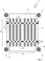
- FIG 1 A schematic representation of a first tool plate 1 according to the invention is shown.
- the tool plate 1 has a substantially rectangular shape with recesses 2 in the corner areas. These recesses serve to create space for tie bars 3 of an injection molding machine.
- the tie bars 3 are not part of the injection molding tool plate but are nevertheless Figure 1 shown.
- the injection mold plate 1 has a plurality of handling elements, namely 144, which are shown as circles.
- the handling elements 4 are arranged in rows, which are shown horizontally in the figure, and in columns, which are shown vertically in the figure.
- the handling elements 4 are spaced apart by a distance s, which in the embodiment shown is 45 mm. Within the rows, the distance between the handling elements 4 is designated r and is 111 mm in the embodiment shown.
- a total of eight handling elements 4 are arranged in a row.
- the eight handling elements 4 in a row are formed by two row groups each consisting of four handling elements 4.
- the distance z between the two row groups is greater than the distance within the row groups. In the embodiment shown, the distance z is 148 mm.
- the distance between the two outer handling elements 4 of a row is designated r max in the drawing and is 814 mm in the embodiment shown.
- three column groups are provided, each consisting of a plurality of handling elements 4.
- Two column groups namely the column group shown at the top and bottom in the figure, each have exactly three handling elements, while the middle column group has twelve handling elements. Since the distance between adjacent handling elements within the column groups is the same and amounts to 45 mm, the distance between adjacent column groups zs is at least twice as large. In the embodiment shown, it is 50 mm greater than the distance between adjacent handling elements within the column groups, i.e. it amounts to a total of 95 mm. This results in a distance of 595 mm between the two outermost handling elements 4 of a column, which is designated s max in the drawing.
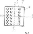
- the distances between the handling elements are larger than in the left part of the figure. It can be seen that due to the larger number of handling elements, the tilting of the plates relative to each other is less pronounced in the left part of the figure.
- the measures according to the invention can therefore reduce the deflection and tilting of the injection mold plates.
Landscapes
- Engineering & Computer Science (AREA)
- Manufacturing & Machinery (AREA)
- Mechanical Engineering (AREA)
- Robotics (AREA)
- Moulds For Moulding Plastics Or The Like (AREA)
- Injection Moulding Of Plastics Or The Like (AREA)
- Processing And Handling Of Plastics And Other Materials For Molding In General (AREA)
Claims (12)
- Machine de moulage par injection avec un outil de moulage par injection pour la production de préformes avec une plaque d'outil de moulage par injection conçue sous la forme d'une plaque de noyau et une plaque d'outil de moulage par injection conçue sous la forme d'une plaque à cavités, la plaque à cavités et la plaque de noyau pouvant être déplacées en va-et-vient l'une par rapport à l'autre entre une position fermée et une position ouverte, dans la position fermée, des éléments de manipulation de la plaque de noyau conçus sous la forme de noyaux étant insérés dans des éléments de manipulation de la plaque à cavités conçus sous la forme de cavités, de sorte que des espaces de moulage se forment entre les noyaux d'une part et les cavités d'autre part, dont le contour intérieur correspond au contour extérieur des préformes à produire, une plaque d'enlèvement pour enlever les préformes à partir de la plaque de noyau, la plaque d'enlèvement pouvant être déplacée en va-et-vient entre une position extérieure, dans laquelle la plaque d'enlèvement n'est pas agencée entre la plaque à cavités et la plaque de noyau, et au moins deux positions d'enlèvement dans lesquelles la plaque d'enlèvement est agencée entre la plaque à cavités et la plaque de noyau, et une plaque d'outil de moulage par injection conçue sous la forme d'une plaque de post-traitement avec une pluralité d'éléments de manipulation agencés en colonnes et en rangées, la distance r entre les éléments de manipulation adjacents à l'intérieur des rangées étant supérieure à la distance s entre des éléments de manipulation adjacents à l'intérieur des colonnes et la distance s étant inférieure à 50 mm, dans le cas de la plaque de post-traitement, les éléments de manipulation étant des élément d'enlèvement, de préférence des broches d'enlèvement, pour enlever les préformes à partir de la plaque d'enlèvement, la plaque d'outil de moulage par injection conçue sous la forme d'une plaque de noyau ou à cavités étant prévue pour produire une pluralité v de préformes avec une pluralité d'éléments de manipulation agencés en colonnes et en rangées, les éléments de manipulation étant des cavités ou des noyaux dont le diamètre intérieur ou extérieur correspond au contour extérieur ou intérieur de la préforme à produire, la distance r entre des éléments de manipulation adjacents à l'intérieur des rangées étant supérieure à la distance s entre des éléments de manipulation adjacents à l'intérieur des colonnes, la distance s étant inférieure à 50 mm, caractérisé en ce que la distance s est comprise entre 44 et 46 mm, la plaque d'outil de moulage par injection comprenant une surface de travail d'une superficie F, tous les éléments de manipulation étant agencés soit à l'intérieur de la surface de travail, soit à la limite de la surface de travail, le nombre d'éléments de manipulation étant égal à t et le rapport étant égal à
 i) la largeur libre entre deux montants, qui sont agencés sur des angles adjacents du rectangle, étant inférieure à 1000 mm, et au moins 136, de préférence au moins 144 éléments de manipulation étant agencés sur la plaque centrale et la plaque à cavités, ouii) la largeur libre entre deux montants qui sont agencés sur des angles adjacents du rectangle étant inférieure à 800 mm, et au moins 120, de préférence au moins 128 éléments de manipulation étant agencés sur la plaque centrale et la plaque à cavités, ouiii) la largeur libre entre deux montants qui sont agencés sur les angles adjacents du rectangle étant inférieure à 750 mm, et au moins 88, de préférence au moins 96 éléments de manipulation étant agencés sur la plaque centrale et la plaque à cavités.
 - Machine de moulage par injection selon la revendication 1, caractérisée en ce que la distance r est inférieure à 140 mm, de préférence inférieure à 120 mm, et de la manière la plus préférée comprise entre 110 et 115 mm.
- Machine de moulage par injection selon la revendication 1 ou la revendication 2, caractérisée en ce que le rapport r/s est compris entre 2,4 et 2,8, et de préférence entre 2,4 et 2,5.
- Machine de moulage par injection selon l'une quelconque des revendications 1 à 3, caractérisée en ce qu'une rangée d'éléments de manipulation est formée par deux groupes de rangées d'éléments de manipulation, la distance z entre les groupes de rangées d'éléments de manipulation étant

- Machine de moulage par injection selon la revendication 4, caractérisée en ce que a < n et de préférence n < 5, et de la manière la plus préférée n = 3.
- Machine de moulage par injection selon la revendication 4 ou 5, caractérisée en ce que chaque groupe de rangées comprend exactement quatre éléments de manipulation.
- Machine de moulage par injection selon l'une quelconque des revendications 1 à 6, caractérisée en ce qu'une colonne d'éléments de manipulation est formée par deux ou trois groupes de colonnes d'éléments de manipulation, pour la distance zs entre les groupes de colonnes d'éléments de manipulation, zs ≥ 2s, s étant la distance entre les éléments de manipulation à l'intérieur d'un groupe de colonnes.
- Machine de moulage par injection selon l'une quelconque des revendications 1 à 7, caractérisée en ce que la distance moyenne g entre tous les éléments de manipulation adjacents à l'intérieur des colonnes est inférieure à 50 mm.
- Machine de moulage par injection selon l'une quelconque des revendications 1 à 8, caractérisée en ce que la distance moyenne f entre tous les éléments de manipulation adjacents à l'intérieur des rangées est inférieure à 120 mm.
- Machine de moulage par injection selon la revendication 7 ou 8, caractérisée en ce qu'une colonne comprend trois groupes de colonnes, de préférence soit- deux groupes de colonnes comprenant chacun exactement trois éléments de manipulation et un groupe de colonnes comprenant exactement douze éléments de manipulation, le groupe de colonnes avec exactement douze éléments de manipulation étant disposé entre les deux groupes de colonnes avec exactement trois éléments de manipulation, ou- deux groupes de colonnes comprenant chacun exactement quatre éléments de manipulation et un groupe de colonnes comprenant exactement huit éléments de manipulation, ou- deux groupes de colonnes comprenant chacun exactement trois éléments de manipulation et un groupe de colonnes comprenant six éléments de manipulation.
- Machine de moulage par injection selon l'une quelconque des revendications précédentes, la plaque d'outil de moulage par injection comprenant une forme sensiblement rectangulaire, des évidements se trouvant dans les zones d'angle de la plaque d'outil de moulage par injection, qui sont prévus pour recevoir les montants d'une machine de moulage par injection.
- Machine de moulage par injection selon l'une quelconque des revendications précédentes, la plaque d'enlèvement comprenant des manchons de réception.
Priority Applications (3)
| Application Number | Priority Date | Filing Date | Title |
|---|---|---|---|
| EP24210089.9A EP4477396A3 (fr) | 2020-04-17 | 2021-04-13 | Plaque d'outil de moulage par injection optimisée et outil de moulage par injection doté de celle-ci |
| EP24210093.1A EP4477397A3 (fr) | 2020-04-17 | 2021-04-13 | Plaque d'outil de moulage par injection optimisée et outil de moulage par injection doté de celle-ci |
| EP24210099.8A EP4477398A3 (fr) | 2020-04-17 | 2021-04-13 | Plaque d'outil de moulage par injection optimisée et outil de moulage par injection doté de celle-ci |
Applications Claiming Priority (2)
| Application Number | Priority Date | Filing Date | Title |
|---|---|---|---|
| DE102020110565.7A DE102020110565A1 (de) | 2020-04-17 | 2020-04-17 | Optimierte Spritzgießwerkzeugplatte sowie Spritzgießwerkzeug mit einer solchen |
| PCT/EP2021/059515 WO2021209428A1 (fr) | 2020-04-17 | 2021-04-13 | Plaque de moule d'injection optimisée et moule d'injection la comprenant |
Related Child Applications (6)
| Application Number | Title | Priority Date | Filing Date |
|---|---|---|---|
| EP24210093.1A Division-Into EP4477397A3 (fr) | 2020-04-17 | 2021-04-13 | Plaque d'outil de moulage par injection optimisée et outil de moulage par injection doté de celle-ci |
| EP24210093.1A Division EP4477397A3 (fr) | 2020-04-17 | 2021-04-13 | Plaque d'outil de moulage par injection optimisée et outil de moulage par injection doté de celle-ci |
| EP24210099.8A Division-Into EP4477398A3 (fr) | 2020-04-17 | 2021-04-13 | Plaque d'outil de moulage par injection optimisée et outil de moulage par injection doté de celle-ci |
| EP24210099.8A Division EP4477398A3 (fr) | 2020-04-17 | 2021-04-13 | Plaque d'outil de moulage par injection optimisée et outil de moulage par injection doté de celle-ci |
| EP24210089.9A Division-Into EP4477396A3 (fr) | 2020-04-17 | 2021-04-13 | Plaque d'outil de moulage par injection optimisée et outil de moulage par injection doté de celle-ci |
| EP24210089.9A Division EP4477396A3 (fr) | 2020-04-17 | 2021-04-13 | Plaque d'outil de moulage par injection optimisée et outil de moulage par injection doté de celle-ci |
Publications (3)
| Publication Number | Publication Date |
|---|---|
| EP4135962A1 EP4135962A1 (fr) | 2023-02-22 |
| EP4135962B1 true EP4135962B1 (fr) | 2025-04-09 |
| EP4135962C0 EP4135962C0 (fr) | 2025-04-09 |
Family
ID=75562724
Family Applications (4)
| Application Number | Title | Priority Date | Filing Date |
|---|---|---|---|
| EP21719562.7A Active EP4135962B1 (fr) | 2020-04-17 | 2021-04-13 | Moule d'injection comprenant une plaque de moule d'injection optimisée |
| EP24210089.9A Pending EP4477396A3 (fr) | 2020-04-17 | 2021-04-13 | Plaque d'outil de moulage par injection optimisée et outil de moulage par injection doté de celle-ci |
| EP24210099.8A Pending EP4477398A3 (fr) | 2020-04-17 | 2021-04-13 | Plaque d'outil de moulage par injection optimisée et outil de moulage par injection doté de celle-ci |
| EP24210093.1A Pending EP4477397A3 (fr) | 2020-04-17 | 2021-04-13 | Plaque d'outil de moulage par injection optimisée et outil de moulage par injection doté de celle-ci |
Family Applications After (3)
| Application Number | Title | Priority Date | Filing Date |
|---|---|---|---|
| EP24210089.9A Pending EP4477396A3 (fr) | 2020-04-17 | 2021-04-13 | Plaque d'outil de moulage par injection optimisée et outil de moulage par injection doté de celle-ci |
| EP24210099.8A Pending EP4477398A3 (fr) | 2020-04-17 | 2021-04-13 | Plaque d'outil de moulage par injection optimisée et outil de moulage par injection doté de celle-ci |
| EP24210093.1A Pending EP4477397A3 (fr) | 2020-04-17 | 2021-04-13 | Plaque d'outil de moulage par injection optimisée et outil de moulage par injection doté de celle-ci |
Country Status (4)
| Country | Link |
|---|---|
| US (2) | US12459180B2 (fr) |
| EP (4) | EP4135962B1 (fr) |
| DE (1) | DE102020110565A1 (fr) |
| WO (1) | WO2021209428A1 (fr) |
Citations (4)
| Publication number | Priority date | Publication date | Assignee | Title |
|---|---|---|---|---|
| US20110305789A1 (en) | 2008-12-12 | 2011-12-15 | Mht Mold & Hotrunner Technology Ag | System for post-treating and transferring preforms |
| US20150044324A1 (en) | 2012-03-16 | 2015-02-12 | Mht Mold & Hotrunner Technology Ag | Injection mold plate and injection mold having such an injection mold plate |
| US20170157832A1 (en) | 2014-08-29 | 2017-06-08 | Mht Mold & Hotrunner Technology Ag | System for the further treatment of preforms produced by means of injection molding |
| US20190351597A1 (en) | 2018-05-17 | 2019-11-21 | Mht Mold & Hotrunner Technology Ag | Universal Plate |
Family Cites Families (5)
| Publication number | Priority date | Publication date | Assignee | Title |
|---|---|---|---|---|
| US4126291A (en) | 1974-10-18 | 1978-11-21 | California Injection Molding Co., Inc. | Injection mold for elongated, hollow articles |
| WO2004073953A1 (fr) | 2003-02-20 | 2004-09-02 | Netstal-Maschinen Ag | Procede et dispositif pour fabriquer des pieces moulees par injection |
| US20090047374A1 (en) | 2007-08-16 | 2009-02-19 | Husky Injection Molding Systems Ltd. | Mold Module |
| DE102010018121B4 (de) | 2010-04-24 | 2013-10-31 | Netstal-Maschinen Ag | Spritzgießmaschine zur Herstellung einer Mehrzahl von Spritzgießteilen in einem Zyklus |
| DE102013110948A1 (de) | 2013-10-02 | 2015-04-02 | Hekuma Gmbh | Verfahren und Vorrichtung zum Verpacken von Spritzgussteilen |
-
2020
- 2020-04-17 DE DE102020110565.7A patent/DE102020110565A1/de active Pending
-
2021
- 2021-04-13 EP EP21719562.7A patent/EP4135962B1/fr active Active
- 2021-04-13 WO PCT/EP2021/059515 patent/WO2021209428A1/fr not_active Ceased
- 2021-04-13 EP EP24210089.9A patent/EP4477396A3/fr active Pending
- 2021-04-13 EP EP24210099.8A patent/EP4477398A3/fr active Pending
- 2021-04-13 US US17/918,996 patent/US12459180B2/en active Active
- 2021-04-13 EP EP24210093.1A patent/EP4477397A3/fr active Pending
-
2025
- 2025-10-13 US US19/356,449 patent/US20260034713A1/en active Pending
Patent Citations (5)
| Publication number | Priority date | Publication date | Assignee | Title |
|---|---|---|---|---|
| US20110305789A1 (en) | 2008-12-12 | 2011-12-15 | Mht Mold & Hotrunner Technology Ag | System for post-treating and transferring preforms |
| US20150044324A1 (en) | 2012-03-16 | 2015-02-12 | Mht Mold & Hotrunner Technology Ag | Injection mold plate and injection mold having such an injection mold plate |
| US9956708B2 (en) | 2012-03-16 | 2018-05-01 | Mht Mold & Hotrunner Technology Ag | Injection mold plate and injection mold having such an injection mold plate |
| US20170157832A1 (en) | 2014-08-29 | 2017-06-08 | Mht Mold & Hotrunner Technology Ag | System for the further treatment of preforms produced by means of injection molding |
| US20190351597A1 (en) | 2018-05-17 | 2019-11-21 | Mht Mold & Hotrunner Technology Ag | Universal Plate |
Non-Patent Citations (17)
| Title |
|---|
| "PET Packaging Technology", 1 January 2002, SHEFFIELD ACADEMIC PRESS, ISBN: 1-84127-222-1, article MICHAEL KOCH: "Chapter 8 - Two-stage injection stretch blow moulding ", pages: 223 - 279, XP009562846 |
| ANONYMOUS: "ASSIEME PARTE CALDA HOT HALF ASSEMBLY", THERMODYNE HOTRUNNER SYSTEMS, 6 May 2006 (2006-05-06), pages 1 - 11, XP093245946, Retrieved from the Internet <URL:https://web.archive.org/web/20060506134101/http://www.sipa.it/tecnologia/Hot_Halves.pdf> |
| ANONYMOUS: "Finish data sheet - GME30.39 - Experimental", CETIE; PET FINISH 25/22-9-3, 1 July 2017 (2017-07-01), XP093354395 |
| ANONYMOUS: "Global PET Preforms Market 2000-2020", ZION MARKET RESEARCH, 1 January 2025 (2025-01-01), XP093354134 |
| ANONYMOUS: "PET MOLDS", MHT (ACCESSED VIA THE WAYBACK MACHINE), 20 May 2018 (2018-05-20), XP093354144, Retrieved from the Internet <URL:http://web.archive.org/web/20180520090421/http:/www.mht-ag.com:80/products/pet-molds.html> |
| ANONYMOUS: "PETplanet Insider", PETPLANET INSIDER, 1 January 2021 (2021-01-01), XP093354361 |
| ANONYMOUS: "Standard Test Method for Determination of Residual Acetaldehyde in Polyethylene Terephthalate Bottle Polymer Using an Automated Static Head-Space Sampling Device and a Capillary GC with a Flame lonization Detector", ASTM INTERNATIONAL; DESIGNATION: F2013 - 10 (REAPPROVED 2016), 1 January 2016 (2016-01-01), XP093354401 |
| ANONYMOUS: "Thread Finish Standards", HUSKY, 1 August 2006 (2006-08-01), XP093354387 |
| D19 - MHT Mold & Hotrunner Technology AG , "The Wayback Machine" |
| D19 - MHT MOLD & HOTRUNNER TECHNOLOGY AG: "The Wayback Machine", 20 May 2018 (2018-05-20), [retrieved on 20251212] |
| D6 - PETplanet Insider |
| D9+D10 - PETPLANET: "Pet Planet insider", 4 November 2019 (2019-11-04), [retrieved on 20251212] |
| HUSKY TECHNOLOGIES: "Self-Cleaning Mold Technology Tutorial Husky Technologies", 6 November 2017 (2017-11-06), XP093354371, Retrieved from the Internet <URL:https://www.youtube.com/watch?v=t98hzsKO_Ak> |
| MOLD MHT, TECHNOLOGY HOTRUNNER: "PET Preform Molds", MHT, 30 December 2022 (2022-12-30), pages 1 - 8, XP093240102 |
| OTTMAR BRANDAU: "Stretch Blow Molding - Third edition", 1 January 2017, ELSEVIER, ISBN: 978-0-323-46177-1, article OTTMAR BRANDAU: "Chapter 2 - Material Basics", pages: 5 - 25, XP009562848, DOI: 10.1016/B978-0-323-46177-1.00002-0 |
| OTTMAR BRANDAU: "Stretch Blow Molding - Third edition", 5 August 2016, ELSEVIER, ISBN: 978-0-323-46177-1, article OTTMAR BRANDAU: "1 - Short History of Stretch Blow Molding", pages: 1 - 4, XP009565620, DOI: 10.1016/B978-0-323-46177-1.00001-9 |
| OTTMAR BRANDAU: "Stretch Blow Molding - Third edition", 5 August 2016, ELSEVIER, ISBN: 978-0-323-46177-1, article OTTMAR BRANDAU: "Chapter 11: Economics", pages: 263 - 299, XP009562857, DOI: 10.1016/B978-0-323-46177-1.00011-1 |
Also Published As
| Publication number | Publication date |
|---|---|
| EP4477396A3 (fr) | 2025-03-05 |
| EP4477398A2 (fr) | 2024-12-18 |
| EP4135962C0 (fr) | 2025-04-09 |
| EP4477398A3 (fr) | 2025-03-05 |
| EP4135962A1 (fr) | 2023-02-22 |
| US20260034713A1 (en) | 2026-02-05 |
| WO2021209428A1 (fr) | 2021-10-21 |
| US12459180B2 (en) | 2025-11-04 |
| US20230063595A1 (en) | 2023-03-02 |
| EP4477397A3 (fr) | 2025-03-05 |
| EP4477397A2 (fr) | 2024-12-18 |
| EP4477396A2 (fr) | 2024-12-18 |
| DE102020110565A1 (de) | 2021-10-21 |
Similar Documents
| Publication | Publication Date | Title |
|---|---|---|
| EP0791448A2 (fr) | Procédé et dispositif pour mouler par injection des articles en matière plastique | |
| EP2286974B1 (fr) | Dispositif de formage et procédé d'enlèvement d'un objet | |
| EP0666791B1 (fr) | Procede de moulage par injection de pieces en matiere thermoplastique et outil permettant la mise en uvre dudit procede | |
| DE60106739T2 (de) | Spritzgiessmaschine für kunststoffbehälter mit schnellformwechseleinrichtung | |
| DE3140711C2 (de) | Mehrfach-Spritzgießform | |
| EP0074473A1 (fr) | Procédé et dispositif pour la fabrication de pièces de forme ou des objets en matière plastique | |
| EP2825361B1 (fr) | Plaque outil de moulage par injection ainsi qu'outil de moulage par injection équipé d'une telle plaque | |
| EP4135962B1 (fr) | Moule d'injection comprenant une plaque de moule d'injection optimisée | |
| DE69903348T2 (de) | Spritzgiesswerkzeug mit dornkernen mit umgekehrter konizität | |
| DE2454134A1 (de) | Blasform- und streckverfahren zur herstellung von hohlen kunststoffartikeln und vorrichtung zur durchfuehrung des verfahrens | |
| DE102016225928A1 (de) | Spritzgusswerkzeug zum Herstellen eines Formteils durch Hinterspritzen einer Folie, sowie Spritzgusswerkzeug-System mit einem derartigen Spritzgusswerkzeug | |
| EP3569381B1 (fr) | Plaque de manipulation | |
| EP0794046A2 (fr) | Procédé pour la fabrication de produits en matière plastique à partir de deux composantes, installation et moule à injection pour la réalisation du procédé | |
| DE60038461T2 (de) | Verbesserungen für spritzgiessformen | |
| EP3787868B1 (fr) | Bloc pourvu de canaux froids | |
| DE102016220972B4 (de) | Spritzgießmaschine mit elektrisch beheiztem Anschnittbereiche bei Spritzgießwerkzeugen mit seitlicher Direkteinspritzung | |
| DE69904654T2 (de) | Verfahren zum Spritzgiessen von Gegenständen aus synthetischen Polymeren/Copolymeren | |
| DE102008056670B4 (de) | Verfahren zum Betreiben einer Spritzgießeinrichtung | |
| DE102024129668A1 (de) | Werkzeug zum Spritzgiessen von Kunststoffteilen und Verfahren zum Entformen von Kunststoffteilen | |
| DE4334251A1 (de) | Verfahren zur Herstellung eines Anhängeelementeaufbaues | |
| DE1704014C3 (de) | Formwerkzeug zur Verarbeitung von in der Wärme vernetzbaren Werkstoffen, insbesondere Kunststoffen | |
| WO1997004944A2 (fr) | Procede et dispositif pour la fabrication de recipients | |
| EP4446087A1 (fr) | Moule d'injection, procédé de nettoyage pour un moule d'injection et procédé de moulage par injection | |
| DE102020122968A1 (de) | Spritzgießwerkzeug | |
| EP1072376A1 (fr) | Procédé et dispositif pour fabriquer un article en matière plastique |
Legal Events
| Date | Code | Title | Description |
|---|---|---|---|
| STAA | Information on the status of an ep patent application or granted ep patent |
Free format text: STATUS: UNKNOWN |
|
| STAA | Information on the status of an ep patent application or granted ep patent |
Free format text: STATUS: THE INTERNATIONAL PUBLICATION HAS BEEN MADE |
|
| TPAC | Observations filed by third parties |
Free format text: ORIGINAL CODE: EPIDOSNTIPA |
|
| PUAI | Public reference made under article 153(3) epc to a published international application that has entered the european phase |
Free format text: ORIGINAL CODE: 0009012 |
|
| STAA | Information on the status of an ep patent application or granted ep patent |
Free format text: STATUS: REQUEST FOR EXAMINATION WAS MADE |
|
| 17P | Request for examination filed |
Effective date: 20221102 |
|
| AK | Designated contracting states |
Kind code of ref document: A1 Designated state(s): AL AT BE BG CH CY CZ DE DK EE ES FI FR GB GR HR HU IE IS IT LI LT LU LV MC MK MT NL NO PL PT RO RS SE SI SK SM TR |
|
| DAV | Request for validation of the european patent (deleted) | ||
| DAX | Request for extension of the european patent (deleted) | ||
| TPAC | Observations filed by third parties |
Free format text: ORIGINAL CODE: EPIDOSNTIPA |
|
| STAA | Information on the status of an ep patent application or granted ep patent |
Free format text: STATUS: EXAMINATION IS IN PROGRESS |
|
| 17Q | First examination report despatched |
Effective date: 20240430 |
|
| TPAC | Observations filed by third parties |
Free format text: ORIGINAL CODE: EPIDOSNTIPA |
|
| TPAC | Observations filed by third parties |
Free format text: ORIGINAL CODE: EPIDOSNTIPA |
|
| TPAC | Observations filed by third parties |
Free format text: ORIGINAL CODE: EPIDOSNTIPA |
|
| GRAP | Despatch of communication of intention to grant a patent |
Free format text: ORIGINAL CODE: EPIDOSNIGR1 |
|
| STAA | Information on the status of an ep patent application or granted ep patent |
Free format text: STATUS: GRANT OF PATENT IS INTENDED |
|
| TPAC | Observations filed by third parties |
Free format text: ORIGINAL CODE: EPIDOSNTIPA |
|
| TPAC | Observations filed by third parties |
Free format text: ORIGINAL CODE: EPIDOSNTIPA |
|
| GRAJ | Information related to disapproval of communication of intention to grant by the applicant or resumption of examination proceedings by the epo deleted |
Free format text: ORIGINAL CODE: EPIDOSDIGR1 |
|
| STAA | Information on the status of an ep patent application or granted ep patent |
Free format text: STATUS: EXAMINATION IS IN PROGRESS |
|
| GRAS | Grant fee paid |
Free format text: ORIGINAL CODE: EPIDOSNIGR3 |
|
| STAA | Information on the status of an ep patent application or granted ep patent |
Free format text: STATUS: GRANT OF PATENT IS INTENDED |
|
| INTG | Intention to grant announced |
Effective date: 20250130 |
|
| GRAA | (expected) grant |
Free format text: ORIGINAL CODE: 0009210 |
|
| STAA | Information on the status of an ep patent application or granted ep patent |
Free format text: STATUS: THE PATENT HAS BEEN GRANTED |
|
| AK | Designated contracting states |
Kind code of ref document: B1 Designated state(s): AL AT BE BG CH CY CZ DE DK EE ES FI FR GB GR HR HU IE IS IT LI LT LU LV MC MK MT NL NO PL PT RO RS SE SI SK SM TR |
|
| INTG | Intention to grant announced |
Effective date: 20250130 |
|
| REG | Reference to a national code |
Ref country code: GB Ref legal event code: FG4D Free format text: NOT ENGLISH |
|
| PLBI | Opposition filed |
Free format text: ORIGINAL CODE: 0009260 |
|
| REG | Reference to a national code |
Ref country code: CH Ref legal event code: EP |
|
| REG | Reference to a national code |
Ref country code: IE Ref legal event code: FG4D Free format text: LANGUAGE OF EP DOCUMENT: GERMAN |
|
| 26 | Opposition filed |
Opponent name: HUSKY INJECTION MOLDING SYSTEMS LTD. Effective date: 20250410 |
|
| U01 | Request for unitary effect filed |
Effective date: 20250409 |
|
| U07 | Unitary effect registered |
Designated state(s): AT BE BG DE DK EE FI FR IT LT LU LV MT NL PT RO SE SI Effective date: 20250415 |
|
| U20 | Renewal fee for the european patent with unitary effect paid |
Year of fee payment: 5 Effective date: 20250416 |
|
| PGFP | Annual fee paid to national office [announced via postgrant information from national office to epo] |
Ref country code: CH Payment date: 20250613 Year of fee payment: 5 |
|
| PGFP | Annual fee paid to national office [announced via postgrant information from national office to epo] |
Ref country code: TR Payment date: 20250630 Year of fee payment: 5 |
|
| PG25 | Lapsed in a contracting state [announced via postgrant information from national office to epo] |
Ref country code: ES Free format text: LAPSE BECAUSE OF FAILURE TO SUBMIT A TRANSLATION OF THE DESCRIPTION OR TO PAY THE FEE WITHIN THE PRESCRIBED TIME-LIMIT Effective date: 20250409 |
|
| PG25 | Lapsed in a contracting state [announced via postgrant information from national office to epo] |
Ref country code: GR Free format text: LAPSE BECAUSE OF FAILURE TO SUBMIT A TRANSLATION OF THE DESCRIPTION OR TO PAY THE FEE WITHIN THE PRESCRIBED TIME-LIMIT Effective date: 20250710 Ref country code: NO Free format text: LAPSE BECAUSE OF FAILURE TO SUBMIT A TRANSLATION OF THE DESCRIPTION OR TO PAY THE FEE WITHIN THE PRESCRIBED TIME-LIMIT Effective date: 20250709 |
|
| PG25 | Lapsed in a contracting state [announced via postgrant information from national office to epo] |
Ref country code: PL Free format text: LAPSE BECAUSE OF FAILURE TO SUBMIT A TRANSLATION OF THE DESCRIPTION OR TO PAY THE FEE WITHIN THE PRESCRIBED TIME-LIMIT Effective date: 20250409 |
|
| PG25 | Lapsed in a contracting state [announced via postgrant information from national office to epo] |
Ref country code: HR Free format text: LAPSE BECAUSE OF FAILURE TO SUBMIT A TRANSLATION OF THE DESCRIPTION OR TO PAY THE FEE WITHIN THE PRESCRIBED TIME-LIMIT Effective date: 20250409 |
|
| PG25 | Lapsed in a contracting state [announced via postgrant information from national office to epo] |
Ref country code: RS Free format text: LAPSE BECAUSE OF FAILURE TO SUBMIT A TRANSLATION OF THE DESCRIPTION OR TO PAY THE FEE WITHIN THE PRESCRIBED TIME-LIMIT Effective date: 20250709 |
|
| PG25 | Lapsed in a contracting state [announced via postgrant information from national office to epo] |
Ref country code: IS Free format text: LAPSE BECAUSE OF FAILURE TO SUBMIT A TRANSLATION OF THE DESCRIPTION OR TO PAY THE FEE WITHIN THE PRESCRIBED TIME-LIMIT Effective date: 20250809 |
|
| PLBI | Opposition filed |
Free format text: ORIGINAL CODE: 0009260 |
|
| PG25 | Lapsed in a contracting state [announced via postgrant information from national office to epo] |
Ref country code: SM Free format text: LAPSE BECAUSE OF FAILURE TO SUBMIT A TRANSLATION OF THE DESCRIPTION OR TO PAY THE FEE WITHIN THE PRESCRIBED TIME-LIMIT Effective date: 20250409 |
|
| REG | Reference to a national code |
Ref country code: CH Ref legal event code: L11 Free format text: ST27 STATUS EVENT CODE: U-0-0-L10-L11 (AS PROVIDED BY THE NATIONAL OFFICE) Effective date: 20260114 |
|
| PLAB | Opposition data, opponent's data or that of the opponent's representative modified |
Free format text: ORIGINAL CODE: 0009299OPPO |
|
| PG25 | Lapsed in a contracting state [announced via postgrant information from national office to epo] |
Ref country code: CZ Free format text: LAPSE BECAUSE OF FAILURE TO SUBMIT A TRANSLATION OF THE DESCRIPTION OR TO PAY THE FEE WITHIN THE PRESCRIBED TIME-LIMIT Effective date: 20250409 |
|
| REG | Reference to a national code |
Ref country code: CH Ref legal event code: L10 Free format text: ST27 STATUS EVENT CODE: U-0-0-L10-L00 (AS PROVIDED BY THE NATIONAL OFFICE) Effective date: 20260121 |
|
| PLAX | Notice of opposition and request to file observation + time limit sent |
Free format text: ORIGINAL CODE: EPIDOSNOBS2 |
|
| PG25 | Lapsed in a contracting state [announced via postgrant information from national office to epo] |
Ref country code: SK Free format text: LAPSE BECAUSE OF FAILURE TO SUBMIT A TRANSLATION OF THE DESCRIPTION OR TO PAY THE FEE WITHIN THE PRESCRIBED TIME-LIMIT Effective date: 20250409 |
|
| PG25 | Lapsed in a contracting state [announced via postgrant information from national office to epo] |
Ref country code: MC Free format text: LAPSE BECAUSE OF FAILURE TO SUBMIT A TRANSLATION OF THE DESCRIPTION OR TO PAY THE FEE WITHIN THE PRESCRIBED TIME-LIMIT Effective date: 20250409 |
|
| 26 | Opposition filed |
Opponent name: S.I.P.A. SOCIETA INDUSTRIALIZZAZIONE PROGETTAZIONEE AUTOMAZIONE S.P.A. Effective date: 20251223 |
|
| R26 | Opposition filed (corrected) |
Opponent name: HUSKY INJECTION MOLDING SYSTEMS LTD. Effective date: 20250410 Opponent name: S.I.P.A. SOCIETA INDUSTRIALIZZAZIONE PROGETTAZIONEE AUTOMAZIONE S.P.A. Effective date: 20251223 |
|
| PGFP | Annual fee paid to national office [announced via postgrant information from national office to epo] |
Ref country code: GB Payment date: 20260306 Year of fee payment: 6 |
|
| PG25 | Lapsed in a contracting state [announced via postgrant information from national office to epo] |
Ref country code: IE Free format text: LAPSE BECAUSE OF NON-PAYMENT OF DUE FEES Effective date: 20250413 |