EP4477396A2 - Plaque d'outil de moulage par injection optimisée et outil de moulage par injection doté de celle-ci - Google Patents
Plaque d'outil de moulage par injection optimisée et outil de moulage par injection doté de celle-ci Download PDFInfo
- Publication number
- EP4477396A2 EP4477396A2 EP24210089.9A EP24210089A EP4477396A2 EP 4477396 A2 EP4477396 A2 EP 4477396A2 EP 24210089 A EP24210089 A EP 24210089A EP 4477396 A2 EP4477396 A2 EP 4477396A2
- Authority
- EP
- European Patent Office
- Prior art keywords
- handling elements
- plate
- injection molding
- distance
- molding machine
- Prior art date
- Legal status (The legal status is an assumption and is not a legal conclusion. Google has not performed a legal analysis and makes no representation as to the accuracy of the status listed.)
- Pending
Links
Images




Classifications
-
- B—PERFORMING OPERATIONS; TRANSPORTING
- B29—WORKING OF PLASTICS; WORKING OF SUBSTANCES IN A PLASTIC STATE IN GENERAL
- B29C—SHAPING OR JOINING OF PLASTICS; SHAPING OF MATERIAL IN A PLASTIC STATE, NOT OTHERWISE PROVIDED FOR; AFTER-TREATMENT OF THE SHAPED PRODUCTS, e.g. REPAIRING
- B29C45/00—Injection moulding, i.e. forcing the required volume of moulding material through a nozzle into a closed mould; Apparatus therefor
- B29C45/17—Component parts, details or accessories; Auxiliary operations
- B29C45/26—Moulds
- B29C45/261—Moulds having tubular mould cavities
-
- B—PERFORMING OPERATIONS; TRANSPORTING
- B29—WORKING OF PLASTICS; WORKING OF SUBSTANCES IN A PLASTIC STATE IN GENERAL
- B29C—SHAPING OR JOINING OF PLASTICS; SHAPING OF MATERIAL IN A PLASTIC STATE, NOT OTHERWISE PROVIDED FOR; AFTER-TREATMENT OF THE SHAPED PRODUCTS, e.g. REPAIRING
- B29C45/00—Injection moulding, i.e. forcing the required volume of moulding material through a nozzle into a closed mould; Apparatus therefor
- B29C45/17—Component parts, details or accessories; Auxiliary operations
- B29C45/72—Heating or cooling
- B29C45/7207—Heating or cooling of the moulded articles
- B29C2045/7214—Preform carriers for cooling preforms
-
- B—PERFORMING OPERATIONS; TRANSPORTING
- B29—WORKING OF PLASTICS; WORKING OF SUBSTANCES IN A PLASTIC STATE IN GENERAL
- B29C—SHAPING OR JOINING OF PLASTICS; SHAPING OF MATERIAL IN A PLASTIC STATE, NOT OTHERWISE PROVIDED FOR; AFTER-TREATMENT OF THE SHAPED PRODUCTS, e.g. REPAIRING
- B29C45/00—Injection moulding, i.e. forcing the required volume of moulding material through a nozzle into a closed mould; Apparatus therefor
- B29C45/17—Component parts, details or accessories; Auxiliary operations
- B29C45/40—Removing or ejecting moulded articles
- B29C45/42—Removing or ejecting moulded articles using means movable from outside the mould between mould parts, e.g. robots
- B29C45/4225—Take-off members or carriers for the moulded articles, e.g. grippers
-
- B—PERFORMING OPERATIONS; TRANSPORTING
- B29—WORKING OF PLASTICS; WORKING OF SUBSTANCES IN A PLASTIC STATE IN GENERAL
- B29K—INDEXING SCHEME ASSOCIATED WITH SUBCLASSES B29B, B29C OR B29D, RELATING TO MOULDING MATERIALS OR TO MATERIALS FOR MOULDS, REINFORCEMENTS, FILLERS OR PREFORMED PARTS, e.g. INSERTS
- B29K2105/00—Condition, form or state of moulded material or of the material to be shaped
- B29K2105/25—Solid
- B29K2105/253—Preform
- B29K2105/258—Tubular
-
- B—PERFORMING OPERATIONS; TRANSPORTING
- B29—WORKING OF PLASTICS; WORKING OF SUBSTANCES IN A PLASTIC STATE IN GENERAL
- B29K—INDEXING SCHEME ASSOCIATED WITH SUBCLASSES B29B, B29C OR B29D, RELATING TO MOULDING MATERIALS OR TO MATERIALS FOR MOULDS, REINFORCEMENTS, FILLERS OR PREFORMED PARTS, e.g. INSERTS
- B29K2995/00—Properties of moulding materials, reinforcements, fillers, preformed parts or moulds
- B29K2995/0037—Other properties
- B29K2995/0094—Geometrical properties
Definitions
- the present invention relates to an injection molding tool plate for use in an injection molding tool for producing preforms with a plurality of handling elements arranged in columns and rows, wherein the distance r between adjacent handling elements within the rows is greater than the distance s between adjacent handling elements within the columns.
- Injection molding is one of the most important processes for producing plastic molded parts.
- the molding compound which is generally originally in the form of a powder or granulate, is heated, plasticized and pressed into a corresponding mold under high pressure.
- the molding compound solidifies in the mold and is then removed from the opened tool.
- commercially available PET bottles are manufactured by stretch blow molding a hollow body preform.
- the preform is created in a first step by injection molding.
- the stretch blow molding that follows the injection molding process can take place either immediately after the preform has been manufactured or at a later point in time.
- injection molds for producing PET preforms.
- Such injection molds have a large number of cavities, e.g. 96, into which appropriately designed tool cores are inserted.
- a space the so-called mold space, is formed between the core on the one hand and the cavity on the other.
- the plasticized plastic, ie PET in the example described here is then injected into this space under high pressure. As soon as the PET preform has cooled sufficiently, the mold can be opened and the preform removed.
- the preform In order to reduce the cycle times, ie the time from In order to reduce the time between one injection process and the next injection process, it is already common practice to remove the preform from the mold at a very early stage, when the preform is already solid on its outer surfaces but the inner area is still liquid. In this state, the preform is generally transferred to a so-called removal plate, which has a set of receiving cavities.
- the set of receiving cavities includes as many receiving cavities as the tool has cores or cavities, so that the solidified preform can be transferred from each core into a receiving cavity.
- the injection molds When producing preforms, the injection molds have two mold halves that can be moved back and forth between an open and a closed position.
- One mold half has the so-called cavity plate, which has a plurality of cavities arranged in columns and rows, wherein the distance r between adjacent cavities within the rows is greater than the distance s between adjacent cavities within the columns.
- the other mold half has a core plate that has corresponding cores that are arranged within the cavities when the mold is closed. Therefore, the cores are also arranged in a plurality of columns and rows, wherein the distance r between adjacent cores within the rows is greater than the distance s between adjacent cores within the columns.
- Both the cores and the cavities are handling elements in the sense of the present invention. Handling elements are all elements that come into contact with or process the preforms during production or removal or the subsequent cooling.
- the plasticized PET melt is usually fed in through openings in the bottom of the cavities.
- the cavity plate is assigned a corresponding hot runner network, which is usually arranged in a hot runner plate positioned next to the cavity plate. Since the sprue, i.e. the point at which the plasticized melt is fed to the hot runner plate, is usually located in the middle of the plate, the hot runner network extends from the sprue to each cavity, with the channels becoming narrower the further they are from the sprue. However, near the sprue, a section of the hot runner will have a relatively large cross-section, so that neighboring cavities cannot be arranged too close to one another.
- a distance of around 140 mm is therefore often maintained between the center of a cavity and the center of the immediately adjacent cavity in the row direction.
- the distance between handling elements is always to be understood as the distance between the center of one handling element and the center of the other handling element.
- a tool with 144 cavities is known in which the distance between handling elements within the columns is 50 mm and the distance within the rows is 140 mm. Due to the size of the injection mold plate, the hot runner, i.e. the channel through which the liquid melt is fed, must also be chosen to be correspondingly long.
- acetaldehyde For example, heating and plasticizing PET inevitably produces small amounts of acetaldehyde.
- the finished PET plastic i.e. the PET bottle, can release this acetaldehyde into the liquid it contains.
- Acetaldehyde is harmless to health in the concentrations usually found here, especially since acetaldehyde is also a natural component of fruit.
- acetaldehyde has an odor that is generally not desired when consuming the liquid stored in the PET bottle.
- mineral water is bottled in PET bottles, the consumer and therefore also the bottle manufacturer only accept a very low concentration of acetaldehyde.
- the concentration of acetaldehyde in PET depends on a number of different factors. Not only the quality of the granulate used plays a role, but also, for example, the pressure and temperature conditions within the screw, the hot runner and the actual mold. Overall, there are dozens of parameters that influence the processability of the melt and thus also the proportion of decomposition products. Basically, the temperature, pressure and residence time of the plasticized melt in the screw, hot runner and mold must be determined in a way that depends on the granulate used. Processing windows must be kept to ensure the processability of the melt and to avoid damage. Within the processing window, the parameters can be varied without any significant deterioration in processability. However, this variation can very well influence the proportion of decomposition products. Therefore, the parameters must be optimized to keep the acetaldehyde concentration low.
- the residence time of the plasticized melt in the hot runner is shortened because the length of the hot runner can be shortened.
- the arrangement leads to a saving of 5 mm in length for each distance between adjacent handling elements within the columns.
- the measure according to the invention leads to a reduction in the length of the injection molding tool plate by at least 90 mm.
- the distance r i.e. the distance between adjacent handling elements within the rows, is less than 140 mm, preferably less than 120 mm and most preferably between 110 and 115 mm. This measure also leads to a more compact arrangement of the individual handling elements, which reduces the disadvantages described.
- the injection mold plates deflect to a small extent. This deflection increases the longer the plate is. This has an impact on the handling elements.
- the effects are essentially determined by the distance between the handling elements. The smaller the distance between the handling elements, the less a deflection of the mold plate has a different effect on adjacent handling elements. Therefore, the handling elements should have distances within the rows that are less than 2.8 times the distances within the columns, otherwise mismatches arise between the individual handling elements and the elements with which they interact due to the deflection of the plates.
- the handling elements By dividing the handling elements into two row groups, they can be arranged on both sides of the sprue, so that within the row groups the distance between the handling elements can be reduced, while the distance z between the handling element of the first row group, which is arranged closest to the second row group, and the handling element of the second row group, which is arranged closest to the first row group of handling elements, is chosen to be larger.
- each row group has exactly four handling elements.
- the distance between handling elements within the row group could be 110 mm, while the distance between the two closest handling elements of the two different row groups is 148 mm (1 + 1/3) x 111 mm.
- a column of handling elements is formed by two or three column groups of handling elements, wherein the distance zs between the column groups of handling elements is zs ⁇ 2s, wherein zs is the distance between the handling elements within a column group. In a preferred embodiment, zs is 95 mm.
- the distances between adjacent handling elements of different column groups can be greater than the distance between adjacent handling elements within a column group, it is advantageous in a preferred embodiment if the average distance s between all adjacent handling elements within the gaps is less than 50 mm.
- the average distance r between all adjacent handling elements within the rows is less than 120 mm.
- handling elements engage with handling elements of adjacent injection mold plates. Therefore, handling elements usually have corresponding centering surfaces, such as conical sections, which contribute to an exact alignment of the injection mold plate to an adjacent injection mold plate.
- the ratio of the distance r max between the most spaced handling elements of a row to the distance s max between the most spaced handling elements of a column is between 0.9 and 1.1, preferably between 0.93 and 1.07, and most preferably between 1 and 1.06.
- the injection molding tool plate has a substantially rectangular shape, with recesses in the corner areas of the injection molding tool plate that are intended to accommodate the bars of an injection molding machine. These recesses can be, for example, laterally open cutouts in the tool plate or through holes.
- the injection molding tool has a removal plate for removing preforms from the core plate, wherein the removal plate preferably has receiving sleeves, wherein the removal plate can be moved back and forth between an outer position in which the removal plate is not arranged between the cavity plate and the core plate, and at least one removal position in which the removal plate is arranged between the cavity plate and the core plate, and an injection molding tool plate of the type mentioned at the beginning designed as a post-treatment plate, wherein in the post-treatment plate the handling elements are removal elements, preferably removal pins, for removing the preforms from the removal plate.
- the injection molding tool is accommodated in an injection molding machine which has four bars arranged on four corner points of a rectangle, wherein the core plate and the cavity plate and preferably also the handling elements provided thereon are arranged between the four bars.
- the clear width between two bars arranged at adjacent corners of the rectangle is less than 1,000 mm and at least 136, preferably at least 144 handling elements are arranged on both the core plate and the cavity plate.
- the clear width between two bars arranged on adjacent corner points of the rectangle is less than 800 mm and at least 120, preferably at least 128 handling elements are arranged on both the core plate and the cavity plate.
- the clear width between two beams arranged on adjacent corners of the rectangle is less than 750 mm and at least 88, preferably at least 96 handling elements are arranged on both the core plate and the cavity plate.
- the injection mold plate can be operated with an injection molding machine that applies a significantly lower clamping force to the injection mold plates and thus to the handling elements.
- a clamping force of less than 30 kN is applied to the injection mold plates per preform to be produced simultaneously.
- a clamping force of more than 20 kN per preform to be produced simultaneously is applied to the injection molding plates.
- the clamping force must be sufficient to hold the injection molding tool during the molding process. If the clamping force is too low, the tool opens, i.e. the injection molding tool plates move apart or open during the injection and/or holding pressure phase, which can lead to burrs forming on the preform. The clamping force must therefore not be set too low. However, a low clamping force saves energy. In addition, the tool wears less.
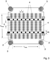
- FIG 1 a schematic representation of a first tool plate 1 according to the invention is shown.
- the tool plate 1 has a substantially rectangular shape with recesses 2 in the corner areas. These recesses serve to create space for the spars 3 of an injection molding machine.
- the spars 3 are not part of the injection molding tool plate but are nevertheless in the Figure 1 shown.
- the injection mold plate 1 has a plurality, namely 144, of handling elements, which are shown as circles.
- the handling elements 4 are arranged in rows, which are shown horizontally in the figure, and in columns, which are shown vertically in the figure.
- the handling elements 4 are spaced apart by a distance s, which in the embodiment shown is 45 mm. Within the rows, the distance between the handling elements 4 is designated by r and is 111 mm in the embodiment shown.
- a total of eight handling elements 4 are arranged in a row.
- the eight handling elements 4 in a row are formed by two row groups each consisting of four handling elements 4.
- the distance z between the two row groups is greater than the distance within the row groups. In the embodiment shown, the distance z is 148 mm.
- the distance between the two outer handling elements 4 of a row is designated r max in the drawing and is 814 mm in the embodiment shown.
- three column groups are provided, each consisting of several handling elements 4.
- Two column groups namely the column group shown at the top and bottom of the figure, each have exactly three handling elements, while the middle column group has twelve handling elements. Since the distance between adjacent handling elements within the column groups is always the same and amounts to 45 mm, the distance between adjacent column groups zs is at least twice as large. In the embodiment shown, it is 50 mm larger than the distance between adjacent handling elements within the column groups, ie it is 95 mm in total. This results in a distance between the two outermost handling elements 4 of a column, which is designated as s max in the drawing, of 865 mm.
- FIG 2 a second embodiment of a tool plate is shown.
- This embodiment has only 128 handling elements, which are arranged in 8 columns and 16 rows. The rows here have only one row group of handling elements.
- three column groups are provided, each consisting of several handling elements 4.
- Two column groups, namely those in the Figure 2 displayed above and below Column groups each have exactly four handling elements, while the middle column group has eight handling elements.
- the distance between the two outer handling elements 4 of a row is designated r max in the drawing and is 777 mm in the embodiment shown.
- three column groups are provided, each consisting of several handling elements 4.
- Two column groups namely the column group shown at the top and bottom of the figure, each have exactly three handling elements, while the middle column group has twelve handling elements. Since the distance between adjacent handling elements within the column groups is always the same and amounts to 45 mm, the distance between adjacent column groups zs is at least twice as large. In the embodiment shown, it is 50 mm greater than the distance between adjacent handling elements within the column groups, ie it is 95 mm in total. This results in a distance between the two outermost handling elements 4 of a column, which is designated as s max in the drawing, of 775 mm.
- FIG 3 A third embodiment of a tool plate is shown. This embodiment has only 96 handling elements, which are arranged in 8 columns and 12 rows. The rows here have only one row group of handling elements. In the column direction, three column groups are provided, each consisting of several handling elements 4. Two column groups, namely those in the Figure 3 The column groups shown above and below each have exactly three handling elements, while the middle column group has six handling elements.
- the distance between the two outer handling elements 4 of a row is designated r max in the drawing and is 777 mm in the embodiment shown.
- three column groups are provided, each consisting of several handling elements 4.
- Two column groups namely the column group shown at the top and bottom of the figure, each have exactly three handling elements, while the middle column group has twelve handling elements. Since the distance between adjacent handling elements within the column groups is always the same and amounts to 45 mm, the distance between adjacent column groups zs is at least twice as large. In the embodiment shown, it is 50 mm greater than the distance between adjacent handling elements within the column groups, ie it is 95 mm in total. This results in a distance between the two outermost handling elements 4 of a column, which is designated as s max in the drawing, of 595 mm.
- FIG 4 the pressure conditions between handling elements of adjacent injection mold plates are shown. If an injection mold plate has a neck ring 11 and a core 14 and the adjacent injection mold plate has a cavity 12 into which the core 14 penetrates in order to form the mold space and the two mold plates are offset from each other in the direction of the arrow, the centering of the handling elements when the injection mold is closed takes place via correspondingly designed conical sections of the neck ring 11 and the cavity. Due to the offset (shown by the arrow), the conical sections will always meet at the same point and there will be increased pressure in an area 13.
- the offset can be significantly reduced, so that wear can be reduced.
- FIG 5 a schematic representation of two injection molding tool plates 21, 22 arranged next to one another is shown.
- Both injection molding tool plates 21, 22 have corresponding handling elements 4.
- On the right-hand side of the figure larger distances are provided between the handling elements 4, as is the case in the prior art.
- On the left-hand side the distances between the individual handling elements 4 are reduced according to the invention. As a result, more support points are provided by the handling elements 4, so that there is less bending of the injection molding tool plates.
- the deflection of the injection molding tool plates is clearly exaggerated. In fact, the deflection is so small that it is hardly visible to the naked eye.
- FIG 6 a schematic representation of two injection molding tool plates 21, 22 arranged one above the other is shown. Due to the weight of the injection molding tool plates and due to thermal effects, tilting, ie rotation of an injection molding tool plate 21 relative to another injection molding tool plate 22 (shown in dashed lines) about an axis that is perpendicular to the injection molding tool plates, can occur.
- the distances between the handling elements are larger than in the left part of the figure. It can be seen that due to the larger number of handling elements, the tilting of the plates towards each other is less pronounced in the left part of the figure.
- the measures according to the invention can therefore reduce the deflection and tilting of the injection molding tool plates.
Landscapes
- Engineering & Computer Science (AREA)
- Manufacturing & Machinery (AREA)
- Mechanical Engineering (AREA)
- Robotics (AREA)
- Moulds For Moulding Plastics Or The Like (AREA)
- Injection Moulding Of Plastics Or The Like (AREA)
- Processing And Handling Of Plastics And Other Materials For Molding In General (AREA)
Applications Claiming Priority (3)
| Application Number | Priority Date | Filing Date | Title |
|---|---|---|---|
| DE102020110565.7A DE102020110565A1 (de) | 2020-04-17 | 2020-04-17 | Optimierte Spritzgießwerkzeugplatte sowie Spritzgießwerkzeug mit einer solchen |
| EP21719562.7A EP4135962B1 (fr) | 2020-04-17 | 2021-04-13 | Moule d'injection comprenant une plaque de moule d'injection optimisée |
| PCT/EP2021/059515 WO2021209428A1 (fr) | 2020-04-17 | 2021-04-13 | Plaque de moule d'injection optimisée et moule d'injection la comprenant |
Related Parent Applications (2)
| Application Number | Title | Priority Date | Filing Date |
|---|---|---|---|
| EP21719562.7A Division EP4135962B1 (fr) | 2020-04-17 | 2021-04-13 | Moule d'injection comprenant une plaque de moule d'injection optimisée |
| EP21719562.7A Division-Into EP4135962B1 (fr) | 2020-04-17 | 2021-04-13 | Moule d'injection comprenant une plaque de moule d'injection optimisée |
Publications (2)
| Publication Number | Publication Date |
|---|---|
| EP4477396A2 true EP4477396A2 (fr) | 2024-12-18 |
| EP4477396A3 EP4477396A3 (fr) | 2025-03-05 |
Family
ID=75562724
Family Applications (4)
| Application Number | Title | Priority Date | Filing Date |
|---|---|---|---|
| EP24210089.9A Pending EP4477396A3 (fr) | 2020-04-17 | 2021-04-13 | Plaque d'outil de moulage par injection optimisée et outil de moulage par injection doté de celle-ci |
| EP24210093.1A Pending EP4477397A3 (fr) | 2020-04-17 | 2021-04-13 | Plaque d'outil de moulage par injection optimisée et outil de moulage par injection doté de celle-ci |
| EP21719562.7A Active EP4135962B1 (fr) | 2020-04-17 | 2021-04-13 | Moule d'injection comprenant une plaque de moule d'injection optimisée |
| EP24210099.8A Pending EP4477398A3 (fr) | 2020-04-17 | 2021-04-13 | Plaque d'outil de moulage par injection optimisée et outil de moulage par injection doté de celle-ci |
Family Applications After (3)
| Application Number | Title | Priority Date | Filing Date |
|---|---|---|---|
| EP24210093.1A Pending EP4477397A3 (fr) | 2020-04-17 | 2021-04-13 | Plaque d'outil de moulage par injection optimisée et outil de moulage par injection doté de celle-ci |
| EP21719562.7A Active EP4135962B1 (fr) | 2020-04-17 | 2021-04-13 | Moule d'injection comprenant une plaque de moule d'injection optimisée |
| EP24210099.8A Pending EP4477398A3 (fr) | 2020-04-17 | 2021-04-13 | Plaque d'outil de moulage par injection optimisée et outil de moulage par injection doté de celle-ci |
Country Status (4)
| Country | Link |
|---|---|
| US (2) | US12459180B2 (fr) |
| EP (4) | EP4477396A3 (fr) |
| DE (1) | DE102020110565A1 (fr) |
| WO (1) | WO2021209428A1 (fr) |
Family Cites Families (9)
| Publication number | Priority date | Publication date | Assignee | Title |
|---|---|---|---|---|
| US4126291A (en) | 1974-10-18 | 1978-11-21 | California Injection Molding Co., Inc. | Injection mold for elongated, hollow articles |
| WO2004073953A1 (fr) | 2003-02-20 | 2004-09-02 | Netstal-Maschinen Ag | Procede et dispositif pour fabriquer des pieces moulees par injection |
| US20090047374A1 (en) | 2007-08-16 | 2009-02-19 | Husky Injection Molding Systems Ltd. | Mold Module |
| US8696347B2 (en) | 2008-12-12 | 2014-04-15 | Mht Mold & Hotrunner Technology Ag | System for post-treating and transferring preforms |
| DE102010018121B4 (de) | 2010-04-24 | 2013-10-31 | Netstal-Maschinen Ag | Spritzgießmaschine zur Herstellung einer Mehrzahl von Spritzgießteilen in einem Zyklus |
| DE102012102266A1 (de) | 2012-03-16 | 2013-09-19 | Mht Mold & Hotrunner Technology Ag | Spritzgießwerkzeugplatte sowie Spritzgießwerkzeug mit einer solchen |
| DE102013110948A1 (de) | 2013-10-02 | 2015-04-02 | Hekuma Gmbh | Verfahren und Vorrichtung zum Verpacken von Spritzgussteilen |
| DE102014112438A1 (de) | 2014-08-29 | 2016-03-03 | Mht Mold & Hotrunner Technology Ag | System zur Weiterbehandlung von mittels Spritzgießen hergestellter Vorformlinge |
| DE102018111875A1 (de) | 2018-05-17 | 2019-11-21 | Mht Mold & Hotrunner Technology Ag | Universalplatte |
-
2020
- 2020-04-17 DE DE102020110565.7A patent/DE102020110565A1/de active Pending
-
2021
- 2021-04-13 EP EP24210089.9A patent/EP4477396A3/fr active Pending
- 2021-04-13 EP EP24210093.1A patent/EP4477397A3/fr active Pending
- 2021-04-13 US US17/918,996 patent/US12459180B2/en active Active
- 2021-04-13 EP EP21719562.7A patent/EP4135962B1/fr active Active
- 2021-04-13 WO PCT/EP2021/059515 patent/WO2021209428A1/fr not_active Ceased
- 2021-04-13 EP EP24210099.8A patent/EP4477398A3/fr active Pending
-
2025
- 2025-10-13 US US19/356,449 patent/US20260034713A1/en active Pending
Also Published As
| Publication number | Publication date |
|---|---|
| EP4477397A3 (fr) | 2025-03-05 |
| DE102020110565A1 (de) | 2021-10-21 |
| EP4477398A2 (fr) | 2024-12-18 |
| US20260034713A1 (en) | 2026-02-05 |
| WO2021209428A1 (fr) | 2021-10-21 |
| EP4135962A1 (fr) | 2023-02-22 |
| EP4477397A2 (fr) | 2024-12-18 |
| EP4135962C0 (fr) | 2025-04-09 |
| EP4477396A3 (fr) | 2025-03-05 |
| EP4135962B1 (fr) | 2025-04-09 |
| US12459180B2 (en) | 2025-11-04 |
| EP4477398A3 (fr) | 2025-03-05 |
| US20230063595A1 (en) | 2023-03-02 |
Similar Documents
| Publication | Publication Date | Title |
|---|---|---|
| EP0791448A2 (fr) | Procédé et dispositif pour mouler par injection des articles en matière plastique | |
| EP3288741B1 (fr) | Appareil d'extrusion de bandes de pneu pour fabrication de bandes de roulement ou flancs et procédé de fabrication de bandes de roulement ou flancs | |
| DE2356764A1 (de) | Beheizungseinrichtung fuer eine spritzgussvorrichtung | |
| EP0666791B1 (fr) | Procede de moulage par injection de pieces en matiere thermoplastique et outil permettant la mise en uvre dudit procede | |
| EP2032329B1 (fr) | Cavité de moule avec canal de refroidissement en forme de méandre | |
| EP2668014B1 (fr) | Procédé de moulage par injection et dispositif de moulage par injection | |
| DE60106739T2 (de) | Spritzgiessmaschine für kunststoffbehälter mit schnellformwechseleinrichtung | |
| DE3140711C2 (de) | Mehrfach-Spritzgießform | |
| EP2825361B1 (fr) | Plaque outil de moulage par injection ainsi qu'outil de moulage par injection équipé d'une telle plaque | |
| DE102015209789A1 (de) | Verfahren und Vorrichtung zur Beeinflussung eines Zusammentreffens von mindestens zwei Kunststoffschmelzen während einer Herstellung eines Formkörpers in einem Spritzgießverfahren | |
| EP4135962B1 (fr) | Moule d'injection comprenant une plaque de moule d'injection optimisée | |
| DE69903348T2 (de) | Spritzgiesswerkzeug mit dornkernen mit umgekehrter konizität | |
| DE10355018A1 (de) | Formnestaufbau | |
| DE102010018121B4 (de) | Spritzgießmaschine zur Herstellung einer Mehrzahl von Spritzgießteilen in einem Zyklus | |
| DE102016225928A1 (de) | Spritzgusswerkzeug zum Herstellen eines Formteils durch Hinterspritzen einer Folie, sowie Spritzgusswerkzeug-System mit einem derartigen Spritzgusswerkzeug | |
| DE2454134A1 (de) | Blasform- und streckverfahren zur herstellung von hohlen kunststoffartikeln und vorrichtung zur durchfuehrung des verfahrens | |
| EP3569381B1 (fr) | Plaque de manipulation | |
| DE60038461T2 (de) | Verbesserungen für spritzgiessformen | |
| DE3943146C2 (de) | Spritz-, Stanz- oder Ziehwerkzeug mit austauschbaren Formwerkzeugen | |
| EP3787868B1 (fr) | Bloc pourvu de canaux froids | |
| DE102016220972B4 (de) | Spritzgießmaschine mit elektrisch beheiztem Anschnittbereiche bei Spritzgießwerkzeugen mit seitlicher Direkteinspritzung | |
| DE102024129668A1 (de) | Werkzeug zum Spritzgiessen von Kunststoffteilen und Verfahren zum Entformen von Kunststoffteilen | |
| DE4334251A1 (de) | Verfahren zur Herstellung eines Anhängeelementeaufbaues | |
| DE102008056670B4 (de) | Verfahren zum Betreiben einer Spritzgießeinrichtung | |
| EP4446087A1 (fr) | Moule d'injection, procédé de nettoyage pour un moule d'injection et procédé de moulage par injection |
Legal Events
| Date | Code | Title | Description |
|---|---|---|---|
| PUAI | Public reference made under article 153(3) epc to a published international application that has entered the european phase |
Free format text: ORIGINAL CODE: 0009012 |
|
| STAA | Information on the status of an ep patent application or granted ep patent |
Free format text: STATUS: THE APPLICATION HAS BEEN PUBLISHED |
|
| AC | Divisional application: reference to earlier application |
Ref document number: 4135962 Country of ref document: EP Kind code of ref document: P |
|
| AK | Designated contracting states |
Kind code of ref document: A2 Designated state(s): AL AT BE BG CH CY CZ DE DK EE ES FI FR GB GR HR HU IE IS IT LI LT LU LV MC MK MT NL NO PL PT RO RS SE SI SK SM TR |
|
| REG | Reference to a national code |
Ref country code: DE Ref legal event code: R079 Free format text: PREVIOUS MAIN CLASS: B29K0105000000 Ipc: B29C0045260000 |
|
| PUAL | Search report despatched |
Free format text: ORIGINAL CODE: 0009013 |
|
| AK | Designated contracting states |
Kind code of ref document: A3 Designated state(s): AL AT BE BG CH CY CZ DE DK EE ES FI FR GB GR HR HU IE IS IT LI LT LU LV MC MK MT NL NO PL PT RO RS SE SI SK SM TR |
|
| RIC1 | Information provided on ipc code assigned before grant |
Ipc: B29K 105/00 20060101ALN20250129BHEP Ipc: B29C 45/42 20060101ALN20250129BHEP Ipc: B29C 45/26 20060101AFI20250129BHEP |
|
| STAA | Information on the status of an ep patent application or granted ep patent |
Free format text: STATUS: REQUEST FOR EXAMINATION WAS MADE |
|
| 17P | Request for examination filed |
Effective date: 20250828 |