EP4136044B1 - Système de rayonnage comportant une voie de secours intégrée au rayonnage - Google Patents
Système de rayonnage comportant une voie de secours intégrée au rayonnage Download PDFInfo
- Publication number
- EP4136044B1 EP4136044B1 EP22726397.7A EP22726397A EP4136044B1 EP 4136044 B1 EP4136044 B1 EP 4136044B1 EP 22726397 A EP22726397 A EP 22726397A EP 4136044 B1 EP4136044 B1 EP 4136044B1
- Authority
- EP
- European Patent Office
- Prior art keywords
- escape
- rack
- aisle
- maintenance
- shelf
- Prior art date
- Legal status (The legal status is an assumption and is not a legal conclusion. Google has not performed a legal analysis and makes no representation as to the accuracy of the status listed.)
- Active
Links
Images


Classifications
-
- B—PERFORMING OPERATIONS; TRANSPORTING
- B65—CONVEYING; PACKING; STORING; HANDLING THIN OR FILAMENTARY MATERIAL
- B65G—TRANSPORT OR STORAGE DEVICES, e.g. CONVEYORS FOR LOADING OR TIPPING, SHOP CONVEYOR SYSTEMS OR PNEUMATIC TUBE CONVEYORS
- B65G1/00—Storing articles, individually or in orderly arrangement, in warehouses or magazines
- B65G1/02—Storage devices
- B65G1/04—Storage devices mechanical
- B65G1/0492—Storage devices mechanical with cars adapted to travel in storage aisles
-
- B—PERFORMING OPERATIONS; TRANSPORTING
- B65—CONVEYING; PACKING; STORING; HANDLING THIN OR FILAMENTARY MATERIAL
- B65G—TRANSPORT OR STORAGE DEVICES, e.g. CONVEYORS FOR LOADING OR TIPPING, SHOP CONVEYOR SYSTEMS OR PNEUMATIC TUBE CONVEYORS
- B65G2207/00—Indexing codes relating to constructional details, configuration and additional features of a handling device, e.g. Conveyors
- B65G2207/40—Safety features of loads, equipment or persons
Definitions
- the present disclosure relates to a shelving system that is used in intralogistics storage and/or order picking systems and that has an escape route that can be designed flexibly and as needed and that meets operator specifications and/or applicable safety standards.
- Conventional shelving systems have shelving modules (RM) which are arranged directly adjacent to one another in a height direction Y of the shelving system and/or directly adjacent to one another in a transverse direction Z of the shelving system, cf. Fig. 7 .
- conventional shelving systems have rail-guided storage and retrieval machines (RBG) to automatically store storage units (LE) in shelf compartments (RF) and retrieve them from the shelf compartments.
- the shelf modules are formed by two shelves (R) aligned parallel to each other, with sections of the shelves being assigned to each shelf module.
- At least one of the storage and retrieval machines is provided, which is operated automatically in a (free) space between the shelves, ie in the shelf aisle (RG).
- each shelf module has a accessible maintenance corridor so that a maintenance technician can inspect the relevant storage and retrieval machine on site in the event of a defect or failure and repair it if necessary. Whenever maintenance technicians are mentioned below, this also includes operators who enter a maintenance corridor for the purpose of troubleshooting.
- the maintenance technician usually enters the rack aisle or maintenance corridor from one of the two (open) front sides of the rack module, where appropriately secured doors are provided.
- the maintenance corridors of higher rack modules can be reached via elevators, ladders or stair towers (TT) arranged at the front.
- the two front entrances to the rack aisle represent two escape routes if no vertical conveyors (lifters) are positioned there.
- the documents DE 10 2015 015 775 A1 (Gebhardt) and DE 10 2019 102 804 A1 or EP 3 696 116 A1 (Klug) discuss various escape routes in the problem area of very long rack aisles, which may additionally be blocked at the front by vertical conveyors on one or both sides.
- the DE 10 2015 015 775 A1 (Gebhardt) assumes a shelving system that (implicitly) has lifters H integrated into the shelving - but no front-side lifters external to the shelving aisle at the entrance and exit - for the vertical transport of the storage units LE. Stair towers are provided on both sides of the front ends of the shelving aisle of this shelving system.
- Fig. 7 shows a schematic plan view of two shelf modules (RM1, RM2) arranged directly next to each other in the transverse direction Z of a shelf system according to the DE 10 2015 015 775 A1 . Additional shelf modules (not shown) are directly adjacent to the shelf modules shown in the height direction Y.
- the escape is alternatively to take place into a maintenance aisle of a horizontally directly adjacent shelving module that is adjacent in a transverse direction Z to the shelving module that is to be maintained and is at the same height, a horizontal tunnel is provided through the affected shelves of the shelving modules involved, which is designed without shelf compartments, i.e. without shelf compartments, and which extends in the transverse direction Z of the shelving system.
- the maintenance aisle of the directly vertically or horizontally adjacent shelving module must also be shut down during maintenance to allow for a potential escape, so that automatic operation of the storage and retrieval machines is not possible there, which reduces the performance of the shelving system in addition to the already failed shelving module.
- emergency shutdowns installed in the passage can be triggered.
- the DE 10 2015 015 775 A1 also discloses a further embodiment in which the escape opening is not formed between adjacent aisles arranged one above the other, but between adjacent aisles spaced parallel in the width direction, so that the escape opening leads through the respective shelf storage unit.
- the DE 10 2019 102 804 A1 assumes a racking system with an analogous design, which also has at least one front-side lifter at the entrance or exit of the racking aisle for vertical transport of the storage units and/or the storage and retrieval machines (roaming).
- This lifter which is located outside the rack, extends over the entire height of the racking aisle and is directly adjacent to the racking aisle, so that escape via this end of the racking aisle is not possible. Access to the maintenance aisles is via the lift-free (front) side of the alley.
- the DE 10 2019 102 804 A1 proposes to provide a pivoting or movable bridge at the height of the maintenance aisle, which enables the maintenance technician to cross the shaft of the front-side lifter horizontally in the longitudinal direction X of the racking system in the event of an escape without falling, and to escape via an external stair tower provided there or an escape ladder attached to the outside of the rack. In a normal position, the bridge does not block the lifter. In this way, an additional escape route is also provided, which solves the problem that arises when the maintenance aisle does not exceed a permissible maximum escape route length (e.g. a maximum of only 50 m).
- a permissible maximum escape route length e.g. a maximum of only 50 m.
- the bridge alone cannot solve the problem of at least one escape route being accessible within the permissible maximum distance (e.g. at a distance of 50 m), because the defective storage and retrieval machine blocks one of the two escape routes. In this case, additional escape routes are required.
- the document US 2012/185080 A1 relates, according to its summary, to a maintenance access system for a storage and retrieval machine having a storage and retrieval machine and automated transport vehicles arranged therein.
- the system comprises at least one maintenance access control unit associated with a portion of the space, defining at least one barrier in the space and a boundary of the portion of the space and configured to substantially prevent the passage of vehicles past the at least one barrier, and a controller connected to the control unit, the controller configured to receive a signal from the at least one control unit to isolate the portion of the space associated with the at least one control unit, the controller closing the at least one barrier isolating the portion of the space and causing the removal or immobilization of vehicles within the portion of the space in response to the signal.
- the document DE 10 2014 003451 A1 relates, according to its summary, to a storage and retrieval machine for a storage rack.
- the storage and retrieval machine comprises one or more horizontal rails that are attached to the storage rack at a defined distance from the floor and extend horizontally along the storage rack, a chassis that can be moved horizontally along the one or more rails, a telescopic mast that is attached to the chassis and has a movable mast section that can be moved vertically relative to the chassis, and a load-bearing device for picking up and delivering goods to be stored or retrieved, which is attached to the telescopic mast and can be moved vertically relative to the telescopic mast.
- the storage rack can be operated by the storage and retrieval machine over the entire rack height.
- the locally applicable rules and legal regulations as well as other wishes of the customer (system operator) must be observed.
- the solution should be independent of whether or not the shelving system provides external lifts at one or both ends of the shelving aisle.
- the total length of the shelving aisle should also be irrelevant, so that even very long shelving aisles with lengths far exceeding the permissible maximum escape route lengths (e.g. 50 m) can be provided with sufficient escape options.
- the rack system of the present disclosure can dispense with shutting down adjacent rack modules during maintenance because, in the event of an escape, the maintenance technician does not have to use any of the other maintenance aisles that are immediately adjacent to the maintenance aisle in which the defective or failed storage and retrieval machine is located.
- the maintenance technician escapes exclusively through the rack by moving along the escape channel integrated into the rack.
- the escape channel extends exclusively through the shelf to an exit that is connected to the outside of the shelf system.
- the escape channel can be freely chosen in the vertical and horizontal direction. The number of escape channels can be freely selected.
- escape channels (depending on the total length of the rack aisle) are provided within the racks that limit the affected maintenance aisle laterally and vertically.
- escape channels can be distributed as desired both over the length of the rack aisle and over the two limiting racks, so that there is always at least one escape option, regardless of the location of the failed rack retrieval machine, which is less than a permissible maximum escape route length (e.g. 50 m) from the location of the failed rack retrieval machine or a fault location.
- the escape channel is integrated directly into a shelving structure, omitting the shelves that would normally be provided.
- An additional stair tower is not required outside the shelving system, which can reduce the requirements for the statics of the shelving structure as well as the investment costs and space requirements.
- the escape options can therefore be scaled as required - regardless of the length of the rack aisles and the number and positioning of lifts.
- the escape takes place in an area of the racking system where no machines, such as storage and retrieval machines and/or lifters, are being moved, so that the risk of collision and injury for the maintenance technician is excluded.
- the shelving systems are very long (aisle length > 100 m) and very high (> 12 m), so that the loss of the corresponding shelf compartments for the Escape channels are disproportionate to the additional effort of an external stair tower and/or switched off adjacent shelving modules.
- the escape channel comprises an escape shaft which extends in the vertical direction through at least one of the shelves and which connects the shelf modules to one another in the vertical direction without shelves.
- the escape takes place essentially in the vertical direction across several shelf modules through the shelf, e.g. via a ladder.
- the height of the shelf system is not important. The required statics are provided by the shelf system itself.
- the escape channel is defined exclusively by the escape shaft, which is arranged at a longitudinal end of the at least one of the shelves and which is directly connected to the outside world at an escape level in the longitudinal direction or transverse direction.
- the escape channel is located at one end of the racks, the escaping maintenance technician does not have to travel lengthwise through the racks to reach the outside world. Few rack spaces are lost.
- the escaping maintenance technician simply climbs vertically through the shelves to the height of an escape level, which is usually located at the bottom of the shelf level.
- the escape shaft may be arranged remote from a longitudinal end of at least one of the shelves.
- the positioning of the escape channel or several escape channels between the longitudinal ends of the rack is required for rack aisles that are longer than a permissible maximum escape route length (e.g. 50 m).
- a permissible maximum escape route length e.g. 50 m.
- the escape shaft or shafts can be positioned so that they are always less than a permissible maximum escape route length, in particular 50 m away from a damaged storage and retrieval machine.
- the escape channel(s) in this case are defined exclusively by escape shafts which are directly connected to the outside world at an escape level in the transverse direction.
- the escape channel(s) further comprise at least one escape corridor which extends to the outside world at the escape level and which connects the escape channel(s) to the outside world in the longitudinal direction.
- the escape channel is connected to an outer long side of the shelving system, provided that no other shelves block the way to the outside world.
- this solution is particularly advantageous for isolated shelving systems where the shelving modules are arranged exclusively vertically one above the other, in order to lose as few shelves as possible to the escape channel.
- the additional lost shelving compartments are intentionally accepted in order to be able to position additional shelving systems or shelving modules in the transverse direction directly adjacent to the affected shelving system.
- the (final) escape takes place exclusively in the longitudinal direction because the transverse direction is blocked by directly adjacent shelving systems.
- the escape channel in the at least one of the shelves comprises exclusively escape corridors which extend in the longitudinal direction and which connect the respective maintenance corridor with the outside world.
- the escaping maintenance technician does not have to climb vertically through the rack. This reduces the risk of falling inside the rack.
- the safety requirements can be more easily met outside the rack, using an external stair tower or fire escape.
- the shelving system further comprises the stair tower or fire escape, which is coupled in the longitudinal direction either directly or indirectly via a connecting bridge to at least one of the shelves, so that each of the escape routes (in the vertical direction) is connected to a predetermined escape level (in the outside world).
- the at least one storage and retrieval machine comprises a plurality of shuttles (single-level or multi-level storage and retrieval machines) which are movable along rails in the longitudinal direction, wherein the rails in the maintenance aisle are attached to the shelf compartments on both sides in the vertical direction and in the transverse direction and extend in the longitudinal direction, and wherein the escape channel is connected to the respective maintenance aisle via a door which comprises partial sections of the rails.
- shuttles single-level or multi-level storage and retrieval machines
- the rails traditionally prevent a transverse escape from the maintenance aisle, even if there are no shelves provided in the racking there.
- the door is provided with sections of the rails so that the shuttle can pass through the door when it is closed. When opened, the door gives the maintenance technician access to the escape channel.
- the door can be monitored for safety reasons to initiate an emergency shutdown of the storage and retrieval machines if the door is opened (accidentally and without warning).
- the door can be locked to prevent it from accidentally opening during automatic operation of a storage and retrieval machine.
- the door consists exclusively of sections that can be manually removed (e.g. by form-fitting) and inserted into the end pieces of the remaining rails.
- Opening and closing the "door” in this case involves more effort for the maintenance technician.
- the rail pieces do not have to be can be mounted movably, so that the door is technically simpler and costs less.
- the door is mounted so that it can move (essentially) in the longitudinal direction.
- the door can be moved into the shelf by applying light pressure, for example, and then pushed sideways lengthways to provide access to the escape channel.
- the door allows the shuttle to pass through when closed, and the maintenance technician to pass through when open.
- the door may be mounted so as to be rotatable about a pivot axis which extends along the height direction (or longitudinal direction).
- the door can be locked in a closed position, in which the shuttle can drive past the door unhindered.
- the locking mechanism prevents the door from opening on its own (unintentionally), which would lead to damage from and/or to the passing shuttle.
- a sensor may be provided which monitors a position of the door and which outputs a signal to a safety controller when the door is in an open position, wherein the safety controller is configured to deactivate the shuttle in the maintenance aisle as soon as the signal is received.
- the rack aisle is longer than the maximum permissible escape route length, in particular 50 m.
- the escape channel can be used to create an additional escape route within the rack without having to shut down neighboring rack modules during maintenance.
- an external lifter is arranged directly at one end or at both ends of the rack aisle, so that storage units and/or the at least one storage and retrieval machine can be transported in the height direction between the rack modules.
- At least one shelf-integrated lifter is provided in one or both of the shelves.
- the (additional) escape channel - in addition to the conventional escape routes at the entrance and exit of the rack aisle - can meet the requirements for very long aisle lengths.
- the shelving system further comprises at least one storage and retrieval machine.
- the Fig. 1 to 3 show three different exemplary embodiments of a shelving system 10.
- the shelving system 10 proposed here is generally used in an intralogistics storage and/or order picking system, such as in a distribution center.
- Intralogistics includes logistical material and goods flows within a company premises, particularly within a company building.
- the term intralogistics was defined to create a distinction from the transport of goods outside the company, which is carried out, for example, by a freight forwarder.
- the "Intralogistics Forum" in the "Association of German Mechanical and Plant Engineering” defines intralogistics as the organization, control, implementation and optimization of the internal flow of goods and materials, the flow of information and the handling of goods in industry, trade or public institutions.
- picking refers to the compilation of a customer-specific required quantity from an assortment of several article types. Picking therefore describes a commission compilation for a customer order, i.e. a removal of partial quantities of larger units of individual articles and their combination and preparation for shipment to the customer.
- the shelving system 10 can be used both in a storage system and in a picking system.
- Fig. 1A shows a side view of a first embodiment 10-1 of a shelving system 10.
- Fig. 1B shows a top view of the shelving system 10-1 of the Fig. 1A .
- the shelving system 10-1 of the Fig. 1 has, by way of example, three shelf modules 12-1 to 12-3 arranged vertically one above the other in the height direction Y. It is understood that more or fewer shelf modules 12 can generally be provided. However, at least two shelf modules 12 are provided which are directly adjacent to one another in the height direction Y of the shelving systems 10.
- Each of the shelf modules 12-1 to 12-3 is made up of (parts or sections of) two shelves 14-1 and 14-2 (cf. Fig. 1B ).
- the shelves 14-1 and 14-2 are aligned and arranged parallel to each other in the longitudinal direction X of the shelving system 10 and are arranged at a distance from each other in a transverse direction Z of the shelving system 10 in order to define a shelf aisle 16 between them.
- the shelf aisle 16 thus represents the (free) space between the two shelves 14-1 and 14-2.
- the rack aisle 16 extends in the longitudinal direction X from a first longitudinal end to the opposite second longitudinal end, where, for example, a (rack-external) lifter 18 is positioned. It is understood that a further lifter 18 could also be positioned at the first longitudinal end of the rack aisle 16, which in the Fig. 1B indicated by a dashed line.
- a lifter 18 is understood to be a stationary vertical conveyor.
- Each of the shelves 14-1 and 14-2 has a plurality of shelves 20, which in the example of Fig. 1 directly adjacent to one another in the longitudinal direction X and in the vertical direction Y.
- the shelf compartments 20 are generally designed to accommodate one or more storage units 22 (one behind the other in the Z direction).
- the shelf compartments 20 can have different dimensions. Preferably, however, the shelf compartments 20 are defined with the same dimensions.
- the shelf compartments 20 are designed to accommodate the storage units 22 sitting (floors or angles) or hanging (side angles).
- the storage units 22 are generally stored and retrieved automatically using storage and retrieval machines 24.
- the shelf module 12-3 is assigned a (single) multi-level storage and retrieval machine 24-1 that can serve four shelf levels arranged one above the other.
- the shelf module 12-2 is assigned four single-level storage and retrieval machines 24-2, each of which can only serve one of the four shelf levels (not specified in more detail).
- Other types of storage and retrieval machines 24 can be used. It goes without saying that more or fewer shelf levels can also be provided per shelf module.
- the shelving system 10-1 of the Fig. 1 one, exemplary single, escape channel 26.
- the escape channel 26 is designed to be integrated into the shelf. This means that the escape channel 26 extends exclusively within the shelf 14. In the area of the escape channel 26, the shelf 14 is designed without shelves. This means that no shelves 20 are provided in the area of the escape channel 26.
- the escape channel 26 is in the Fig. 1 exclusively defined by a (vertical) escape shaft 28, which is preferably positioned at the longitudinal end of the first rack 14-1 in the immediate vicinity of the rack-external lifter 18.
- the escape shaft 28 of the Fig. 1 extends in the height direction Y over all three shelf modules 12-1 to 12-3.
- the escape shaft 28 is provided with a ladder 30 on the inside so that a maintenance technician (not shown) who is in the upper shelf modules 12-2 and 12-3 can descend to a floor level (escape level) in order to leave the escape channel 26 either in the longitudinal direction X and/or in the transverse direction Z into an outside world of the shelf system 10, as shown in Fig. 1B is indicated by dash-dotted arrows.
- the escape channel 26 represents a second escape option (escape route) in addition to the open first longitudinal end of the rack aisle 16.
- each shelf module 12 can fail at any point within the rack aisle 16. Therefore, within the rack aisle 16 in the example of the Fig. 1 A maintenance aisle 32 is provided for each of the shelf modules 12-1 to 12-3.
- each of the shelf modules 12-1 to 12-3 is equipped with walkable (eg grid-shaped) plates in its floor area, so that the maintenance technician can walk in the maintenance aisle 32 from each shelf module 12 to the defective or broken storage and retrieval machine 24 and can also repair the storage and retrieval machine 24 there.
- the maintenance technician can Fig. 1 enter the corresponding maintenance aisle 32 either from the open side of the rack aisle 16 or via the escape channel 26.
- the first embodiment of the shelving system 10-1 is particularly suitable for short shelving aisles 16 with a total length L G that is shorter than or equal to the permissible maximum escape route length, e.g. ⁇ 50 m, because a further escape route is created in the immediate vicinity of the blocked aisle end.
- escape channel 26 or the escape shaft 28 can also be positioned at another location in the longitudinal direction X within the corresponding shelf 14.
- the escape channel 26 is at the escape level but only in the Transverse direction Z accessible if no (horizontal) escape route 34 (cf. Fig. 2 ) is additionally provided.
- a further lift 18 could also be provided at the first longitudinal end, so that the rack aisle 16 or the maintenance aisles 32-1 to 32-3 of the Fig. 1 can only be accessed via escape channel 26.
- one or more escape channels 26 can be provided simultaneously in each of the shelves 14-1 and 14-2.
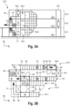
- Fig. 2 shows an exemplary second embodiment of a shelving system 10-2, wherein the Fig. 2A shows a side view and the Fig. 2B a top view of the shelving system 10-2 of the Fig. 2A shows.
- the shelving system 10-2 of the Fig. 2 is almost identical to the shelving system 10-1 of the Fig. 1 Therefore, the differences will be examined in more detail below.
- the shelving system 10-2 of the Fig. 2 has, as an example, three shelf modules 12-1 to 12-3, which are directly adjacent to one another vertically.
- the shelf modules 12-1 to 12-3 are in turn formed by the two shelves 14-1 and 14-2, which in turn define the shelf aisle 16 between them.
- another lifter 18-2 is positioned at the first longitudinal end of the aisle 16.
- the lifters 18 extend over the entire height of the rack system 10-2.
- the rack aisle 16 or the maintenance aisles 32-1 to 32-3 cannot therefore be accessed via the aisle 16.
- the maintenance aisles 32-1 to 32-3 can only be accessed via the escape channel(s) 26.
- the escape channel 26 is again arranged in the first shelf 14-1.
- the escape channel 26 of the Fig. 2 but deviates from the escape channel 26 of the Fig. 1 of an escape shaft 28 and an escape corridor 34.
- the escape shaft 28 of the Fig. 2 extends in the vertical direction Y through all shelf modules 12-1 to 12-3 to the floor of the shelf system 10-2, where the escape level is arranged.
- the escape corridor 34 extends in the longitudinal direction X from the escape shaft 28 through the shelf 14-1 to the outside (outside world) of the shelf 14-1.
- the (horizontal) escape corridor 34 extends in the height direction Y, for example, over one or more shelf compartments 20.
- the height and width of the escape aisle 34 are generally selected so that the maintenance technician can cross the escape aisle 34 without collision, even in a hurry. If the shelf compartments 20 are set up for multiple-depth storage of the storage units 22, only a rear part of the affected shelf compartments 20 can be omitted in order to create space for the escape aisle 34, so that the affected storage compartments 20 can still be served by the storage and retrieval machine 24 via the shelf aisle 16.
- the escape shaft 28 is dimensioned for one escape and replaces a large number of storage compartments 20 in the height direction Y.
- the escape shaft 28 is dimensioned for one escape and replaces a large number of storage compartments 20 in the height direction Y.
- some of the affected shelf compartments 20 are only partially omitted in a rear area.
- access to the escape shaft 28 must be guaranteed in the floor area of the respective maintenance aisle 32, so that the affected shelf compartments 20 are completely omitted there.
- the escape shaft 28 in the highest shelf module 12, here the shelf module 12-3, does not have to reach all the way to the top (not shown in Fig. 2A ), so that shelves 20 can continue to remain there for normal use by the storage and retrieval machine 24.
- the shelving system 10-2 of the Fig. 2 further illustrates that the escape channel 26 can generally be positioned along the longitudinal direction X at any position within the affected shelf 14.
- the embodiment of the Fig. 2 is particularly suitable for storage and/or order picking systems where several of the shelf arrangements 10-2 are arranged next to each other and directly adjacent to each other in the transverse direction Z. In this case, escape in the transverse direction Z from the shelf system 10-2 is not possible, so that the maintenance technician can only escape from the affected shelf system 10-2 in the longitudinal direction X.
- the side view of the Fig. 2A The L-shape of the escape channel 26 indicated could also be designed in a stepped manner (not shown).
- the escape channel 26 would be divided into three vertical sections, for example, which can be displaced relative to one another in the longitudinal direction X for each shelf module 12 and connected to one another via a corresponding escape route 34 (not shown) within the shelf 14 in question.
- escape channels 26 which are provided in the same shelf 14 and which extend essentially in the vertical direction Y through the corresponding shelf 14, to one another via one or more (horizontal) escape aisles 34. It is understood that the more escape shafts 28 and escape aisles 34 are provided, the more shelf compartments 20 are lost. However, this (supposed) reduction in storage capacity is compensated for by the required design of the shelf system with regard to sufficient escape options.
- Fig. 3 shows a third exemplary embodiment of a shelving system 10-3.
- the shelving system 10-3 of the Fig. 3 differs from the shelving systems 10-1 and 10-2 of the Fig. 1 and 2 essentially because the escape channel 26 is formed exclusively by (horizontal) escape passages 34.
- Each of the maintenance aisles 32-1 to 32-3 is connected to an escape aisle 34.
- the escape aisles 34-1 and 34-2 of the shelf modules 12-1 and 12-2 are arranged directly at the longitudinal end of the first shelf 14-1 and are therefore shorter than the escape aisle 34-3 of the third shelf module 12-3, which is arranged somewhat away from the longitudinal end of the shelf 14-1.
- All three escape routes 34-1 to 34-3 of the Fig. 3 lead in the longitudinal direction X out of the shelving system 10-3 or out of the shelf 14-1. There are no escape shafts 28.
- a stair tower 36 is provided outside the shelving system 10-3.
- the stair tower 36 connects to the shelving system 10-3 from the outside.
- the stair tower 36 connects to the lift 18-2 in the longitudinal direction X.
- the first shelf 14-1 is coupled to the stair tower 36 via a connecting bridge 38.
- the (horizontal) connecting bridge 38 can be configured as desired in terms of a course in order to connect the escape corridors 34 to the stair tower 36.
- stair tower 36 can generally also be replaced by an escape ladder 40, a passenger lift or the like, which is attached directly to the longitudinal end of the shelves 14 or to the lifter 18, so that the stair tower 36 and the connecting bridges 38 can be dispensed with.
- the third embodiment which does not require escape shafts 28, is particularly suitable for shelving arrangements where several shelving systems 10 are arranged next to each other in the transverse direction Z and directly adjacent to each other, as is shown in the Fig. 3B indicated by dashed lines.
- the shelving system 10-3' has further escape routes 34' and 34".
- the escape route 34' extends in the upper shelving module 12-3' in the transverse direction Z through the second shelf 14" and connects to the inside of the shelf 14-1 of the shelving system 10-3 in order to define another escape route F', which in the Fig. 3B is indicated by a dashed line.
- the maintenance technician escapes to another shelf module, but its automatic operation does not have to be switched off because the maintenance technician does not move in shelf aisle 16 when he escapes.
- a further (optional) escape passage 34-2' is shown, which extends essentially in the longitudinal direction X through the shelf 14-1' to the outside world in order to define a further escape route F" which comprises a further connecting web 38'.
- the further connecting web 38' extends around the lift 18' of the shelving system 10-3' and connects to the connecting web 38 of the shelving system 10-3 in order to be indirectly coupled to the stair tower 36.
- escape corridors 34' and 34 For the other escape corridors 34' and 34", it should be noted that the associated escape routes F' and F" lead directly to the outside world, i.e. do not use any other maintenance corridor 32 for escape.
- escape channels 26 can be provided in the other shelves 14.
- a further escape passage 34-4 is shown, which is arranged in the second shelf 14-2 of the shelf system 10-3 and which defines a further escape route F4 to the longitudinal end of the shelf 14-2, where the lift 18-1 is arranged.
- the escape route F4 connects to a (fire) ladder 40, which is attached to the outside of the shelf 14-2 and which can reach to the ground.
- Fig. 3B optional doors 42 and 42' are shown, which connect the escape channels 26 and escape corridors 34 with the associated maintenance corridors 32.
- the doors 42 will be described in more detail below.
- the doors 42 of the Fig. 3B open, for example, into the associated maintenance aisle 32. In the open position, the doors 42 block movement of the (not shown) storage and retrieval machines 24.
- the doors 42 are set up so that the doors 42 allow the storage and retrieval machines 24 to pass through when closed. This applies regardless of whether this is a single-level or a multi-level storage and retrieval machine 24.
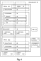
- Fig. 4 shows a schematic block diagram of the shelving system 10 to illustrate the general structure of the shelving system 10.
- the Fig. 4 illustrates in particular a "smallest unit" of the shelving system 10.
- the shelving system 10 has at least two shelving modules 12-1 and 12-2, which are directly adjacent to one another in the vertical direction Y and/or the transverse direction Z of the shelving system 10.
- the shelving modules 12-1 and 12-2 are formed from the first shelf 14-1 and the second shelf 14-2.
- the shelves 14-1 and 14-2 are arranged parallel to one another in the longitudinal direction X of the shelving system 10 and spaced apart from one another in the transverse direction Z of the shelving system in order to define the shelf aisle 16 between them.
- the shelves 14-1 and 14-2 each have a plurality of shelf compartments 20.
- the shelf compartments 20 - with the exception of the escape channels 26 - are directly adjacent to one another at least in the longitudinal direction X (and usually also in the vertical direction Y, depending on the design of the shelf module 12).
- the shelf modules 12 can have one or more shelf levels.
- the shelf modules can have different numbers of shelf levels.
- Each of the shelf modules 12-1 and 12-2 has a maintenance aisle 32 in the area of the shelf aisle 16. This means that in the shelf aisle 16 the two maintenance aisles 32-1 and 32-2 are arranged vertically one above the other.
- Each of the maintenance aisles 32 is set up for the automatic operation of one or more storage and retrieval machines 24. This means that the maintenance aisles 32 meet safety standards, such as being monitored (via video and sensors) in order to be able to detect the access of the maintenance technician in order to be able to initiate an emergency shutdown via a safety control 44, which can also be a component of the shelving system 10.
- safety standards such as being monitored (via video and sensors) in order to be able to detect the access of the maintenance technician in order to be able to initiate an emergency shutdown via a safety control 44, which can also be a component of the shelving system 10.
- the maintenance aisles 32 are also set up for manual maintenance of the storage and retrieval machines 24 and for troubleshooting. This means that, for example, floors are installed in the rack aisle 16 in order to make the rack modules 12 accessible (independently of one another).
- the storage and retrieval machines 24 themselves are optional components of the shelving system 10 and can be provided by suppliers other than the shelving supplier.
- a rack-integrated (shelf-compartment-free) escape channel 26 is provided, which connects the maintenance aisles 32 directly with the outside world of the rack system 10 and which is designed to be traversed by the maintenance technician. This means that the escape channel 26 is sufficiently large for the maintenance technician to fit through.
- the escape channel 26 is provided in the first shelf 14-1 as an example.
- the escape channel 26 can additionally or alternatively also be provided in the second channel 14-2.
- several escape channels 26 can be provided independently of one another.
- the escape channel 26 can be formed from escape shafts 28 and/or escape passages 34.
- connection between the escape channel 26 and the maintenance corridors 32 can be made via one or more doors 42.
- the doors 42 are optional.
- the doors 42 are mandatory if the storage and retrieval machine(s) 24 are moved along (guide) rails 48 that are not (centrally) attached to the floor and/or ceiling of the maintenance aisle 32 but are attached to the sides of the shelf compartments 20. Access to the escape channels 26 is generally from the maintenance aisle 32 in the transverse direction Z into the shelves 14.
- the number and relative positioning of the escape channels 26 in the shelves 14 depends in particular on the length L G of the rack aisle 16 and on the positioning of the lifters 18. If the entrance and/or exit of the rack aisle 16 is blocked by a (rack-external) lifter 18, more rack-integrated escape channels 26 are required.
- the rack-external lifters 18 represent optional components of the rack system 10.
- the number of escape channels 26 does not depend on whether there are lifts 18 integrated into the rack.
- the number of lifts 18 integrated into the rack is also irrelevant.
- the lifts 18 integrated into the rack only have an influence on how the escape channel 26 runs through the corresponding shelf 14, since the shelf-integrated lifters 18 cannot usually be crossed by an escape route 34 in the longitudinal direction X.
- the storage units 22 are stored several times deep in the shelf compartments 20, there may be sufficient space in the depth of the shelves 14 (ie in the transverse direction Z) even in the area of the shelf-integrated lifters 18 to guide the maintenance technician horizontally and/or vertically past the shelf-integrated lifter 18. This depends on the specific configuration of the shelves 14 and the shelf-integrated lifter 18.
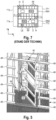
- Fig. 5 shows a perspective partial view of a maintenance passage 32.
- a door 42 is shown which can be opened into the shelf 14.
- Floor elements 46 and rails 48 for lateral forced guidance of (not shown exemplary) single-level storage and retrieval machines (shuttle) 24 are shown.
- six rails 48 are shown one above the other in the vertical direction Y.
- the top rail 48 is continuous.
- the bottom five rails 48 are interrupted in the area of the door 42.
- Sections 50 of the rails 48 are attached to the door 42.
- the sections 50 are dimensioned and arranged such that the interrupted rails 48 are almost uninterrupted when the door 42 is in the closed position. It is understood that in the end areas of the sections 50 there may be small gaps relative to the remaining rails 48. However, this does not interfere with the shuttle when passing through the door 42.
- the door 42 connects the maintenance aisle 32 in the transverse direction Z of the shelving system 10 with an area of the shelving 14 without shelves.
- the floor elements 46 which are designed in a grid-like manner here as an example, are not only provided in the area of the shelving aisle 16 or the maintenance aisle 32, but also within the shelving 14.
- the floor elements 46 within the shelving 14 can also extend laterally (in the longitudinal direction X) in order to give the maintenance technician sufficient space to open and close the door 42 before the maintenance technician enters the maintenance aisle 32.
- the maintenance technician can either climb up or down via the escape shaft 28, which is located behind the door, for example.
- the maintenance technician can also escape sideways via an escape aisle 34 integrated into the shelving system, which is in the Fig. 5 horizontally to the right.
- the door 42 shown comprises, in addition to the sections 50, a door leaf formed from a grid which is pivotally mounted about a vertical axis.
- the door can also be formed solely by the sections 50, as is exemplified in Fig. 6 is indicated.
- the sections 50 are loosely inserted into receiving elements that are arranged in the area of the ends of the remaining rails 48.
- the receiving elements are designed to receive the sections 50 in a form-fitting manner.
- the sections 50 are manually inserted or removed by the maintenance technician. Removal takes place sequentially.
- Such a design of the door 42 is particularly suitable for escape routes that are not actually intended to be used and are only intended to increase safety because there are sufficient other escape routes available.
- doors 42 can alternatively be designed as sliding doors or folding doors.
- the storage and retrieval machine 24 is designed as a multi-level storage and retrieval machine that is guided along rails arranged in the floor and ceiling area of the maintenance aisle 32, the doors 42 can be completely dispensed with.
- the escape channels 26 are accessible via openings in the side shelf area.
- safety sensors can be provided in the area of the doors 42 to monitor whether a corresponding door is in an open or closed position. This information is relevant to the safety controller 44. When the door 42 is in the open position, the storage and retrieval machines 24 of the associated maintenance aisle must definitely be switched off.
Landscapes
- Engineering & Computer Science (AREA)
- Mechanical Engineering (AREA)
- Warehouses Or Storage Devices (AREA)
Claims (14)
- Installation de rayonnage (10) qui présente :au moins deux modules de rayonnage (12) qui sont directement adjacents dans une direction de la hauteur (Y) de l'installation de rayonnage (10) ;dans laquelle les modules de rayonnage (12) sont formés à partir de deux rayons (14) quisont orientés parallèlement l'un à l'autre dans une direction longitudinale (X) de l'installation de rayonnage (10) et sont disposés à distance l'un de l'autre dans une direction transversale (Z) de l'installation de rayonnage (10), afin de définir entre eux une allée entre les rayons (16), etprésentent une pluralité de compartiments de rayonnage (20) directement adjacents ;dans laquelle chacun des modules de rayonnage (12) présente, dans la zone de l'allée entre les rayons (16), un couloir d'entretien (32) qui est conçu pour le fonctionnement automatique et l'entretien manuel d'au moins un appareil de desserte de rayons (24) ;dans laquelle, à l'intérieur d'au moins l'un des rayons (14), un canal d'évacuation (26) intégré au rayon est prévu pour relier directement les couloirs d'entretien (32) à un environnement extérieur de l'installation de rayonnage (10), et dans laquelle le canal d'évacuation (26) est conçu pour être traversé par un technicien d'entretien ; etdans laquelle le canal d'évacuation (26) comprend une cage d'évacuation (28) qui s'étend dans la direction de la hauteur (Y) à travers l'au moins un des rayons (14) et qui relie les modules de rayonnage (12) entre eux sans compartiment de rayonnage dans la direction de la hauteur (Y).
- Installation de rayonnage (10) selon la revendication 1, dans laquelle le canal d'évacuation (26) est défini exclusivement par la cage d'évacuation (28) qui est disposée à une extrémité longitudinale de l'au moins un des rayons (14) et qui est directement reliée à l'environnement extérieur à un niveau d'évacuation dans la direction longitudinale (X) ou dans la direction transversale (Z).
- Installation de rayonnage (10) selon la revendication 1, dans laquelle la cage d'évacuation (28) est disposée à distance d'une extrémité longitudinale de l'au moins un des rayons (14).
- Installation de rayonnage (10) selon la revendication 3, dans laquelle le canal d'évacuation (26) est défini exclusivement par la cage d'évacuation (28) qui est directement reliée à l'environnement extérieur à un niveau d'évacuation dans la direction transversale (Z).
- Installation de rayonnage (10) selon la revendication 3, dans laquelle le canal d'évacuation (26) comprend en outre un couloir d'évacuation (34) qui s'étend à un niveau d'évacuation dans la direction longitudinale (X) entre la cage d'évacuation (28) et l'environnement extérieur et qui relie le canal d'évacuation (26) à l'environnement extérieur dans la direction longitudinale (X).
- Installation de rayonnage (10) qui présente :au moins deux modules de rayonnage (12) qui sont directement adjacents dans une direction de la hauteur (Y) de l'installation de rayonnage (10) ;dans laquelle les modules de rayonnage (12) sont formés à partir de deux rayons (14) quisont orientés parallèlement l'un à l'autre dans une direction longitudinale (X) de l'installation de rayonnage (10) et sont disposés à distance l'un de l'autre dans une direction transversale (Z) de l'installation de rayonnage (10), afin de définir entre eux une allée entre les rayons (16), etprésentent une pluralité de compartiments de rayonnage (20) directement adjacents ;dans laquelle chacun des modules de rayonnage (12) présente, dans la zone de l'allée entre les rayons (16), un couloir d'entretien (32) qui est conçu pour le fonctionnement automatique et l'entretien manuel d'au moins un appareil de desserte de rayons (24) ;dans laquelle, à l'intérieur d'au moins l'un des rayons (14), un canal d'évacuation (26) intégré au rayon est prévu pour relier directement les couloirs d'entretien (32) à un environnement extérieur de l'installation de rayonnage (10), et dans laquelle le canal d'évacuation (26) est conçu pour être traversé par un technicien d'entretien ;dans laquelle le canal d'évacuation (26) dans l'au moins un des rayons (14) comprend exclusivement des couloirs d'évacuation (34) qui s'étendent dans la direction longitudinale (X) et qui relient directement le couloir d'entretien (32) respectif à l'environnement extérieur ; etdans laquelle l'installation de rayonnage (10) comprend en outre une tour d'escalier (36) qui est accouplée dans la direction longitudinale (X) soit directement, soit indirectement par l'intermédiaire d'une entretoise de liaison (38), à l'au moins un des rayons (14), de sorte que les couloirs d'évacuation (34) sont reliés entre eux dans la direction de la hauteur (Y).
- Installation de rayonnage (10) selon l'une des revendications précédentes, dans laquelle l'au moins un appareil de desserte de rayons (24) comprend une pluralité de navettes qui sont mobiles le long de rails (48) en étant guidées dans la direction longitudinale (x), dans laquelle les rails (48) sont montés dans le couloir d'entretien (32) les uns au-dessus des autres dans la direction de la hauteur (Y) et des deux côtés sur les compartiments de rayonnage (20) dans la direction transversale (Z) et s'étendent dans l'allée entre les rayons (16) dans la direction longitudinale (X), et dans laquelle le canal d'évacuation (26) est relié au couloir d'entretien (32) par l'intermédiaire d'une porte (42) qui comprend des sections partielles (50) des rails (48).
- Installation de rayonnage (10) selon la revendication 7, dans laquelle la porte (42) :est constituée exclusivement des sections partielles (50) qui peuvent être stockées de manière amovible manuellement dans une pièce d'extrémité du rail (48) respectif ;est montée de manière à pouvoir coulisser dans la direction longitudinale (X) ; ouest montée de manière à pouvoir tourner autour d'un axe de pivotement qui s'étend le long de la direction de la hauteur (Y) ou de la direction longitudinale (X).
- Installation de rayonnage (10) selon la revendication 7 ou 8, dans laquelle la porte (42) peut être bloquée dans une position fermée dans laquelle les navettes peuvent passer devant la porte (42).
- Installation de rayonnage (10) selon l'une des revendications 7 à 9, dans laquelle un capteur est prévu, lequel surveille une position de la porte (42) et émet un signal vers une commande de sécurité (44) lorsque la porte (42) se trouve dans une position ouverte, dans laquelle la commande de sécurité (44) est configurée pour désactiver la navette dans le couloir d'entretien (32) associé dès que le signal est reçu.
- Installation de rayonnage (10) selon l'une des revendications précédentes, dans laquelle l'allée entre les rayons (16) est plus longue qu'une longueur de voie d'évacuation maximale autorisée.
- Installation de rayonnage (10) selon la revendication 11, dans laquelle la longueur de voie d'évacuation maximale autorisée est de 50 m.
- Installation de rayonnage (10) selon l'une des revendications précédentes, dans laquelle un élévateur (18) externe au rayon est disposé directement à une extrémité, ou respectivement aux deux extrémités, de l'allée entre les rayons (16), de sorte que des unités de stockage (LE) et/ou l'au moins un appareil de desserte de rayons (24) peuvent être transportés dans la direction de la hauteur (Y) entre les modules de rayonnage (12).
- Installation de rayonnage (10) selon l'une des revendications précédentes, dans laquelle au moins un élévateur (18) intégré au rayon est prévu dans l'un des rayons (14) ou dans les deux rayons.
Applications Claiming Priority (2)
| Application Number | Priority Date | Filing Date | Title |
|---|---|---|---|
| DE102021111497.7A DE102021111497A1 (de) | 2021-05-04 | 2021-05-04 | Regalanlage mit regalintegriertem Fluchtweg |
| PCT/EP2022/061255 WO2022233681A1 (fr) | 2021-05-04 | 2022-04-27 | Système de rayonnage comportant une voie de secours intégrée au rayonnage |
Publications (3)
| Publication Number | Publication Date |
|---|---|
| EP4136044A1 EP4136044A1 (fr) | 2023-02-22 |
| EP4136044B1 true EP4136044B1 (fr) | 2024-11-13 |
| EP4136044C0 EP4136044C0 (fr) | 2024-11-13 |
Family
ID=81984583
Family Applications (1)
| Application Number | Title | Priority Date | Filing Date |
|---|---|---|---|
| EP22726397.7A Active EP4136044B1 (fr) | 2021-05-04 | 2022-04-27 | Système de rayonnage comportant une voie de secours intégrée au rayonnage |
Country Status (5)
| Country | Link |
|---|---|
| US (1) | US12459736B2 (fr) |
| EP (1) | EP4136044B1 (fr) |
| DE (1) | DE102021111497A1 (fr) |
| ES (1) | ES3003913T3 (fr) |
| WO (1) | WO2022233681A1 (fr) |
Families Citing this family (2)
| Publication number | Priority date | Publication date | Assignee | Title |
|---|---|---|---|---|
| AT525764A1 (de) * | 2021-12-22 | 2023-07-15 | Tgw Mechanics Gmbh | Regallagersystem |
| US12446690B2 (en) | 2024-01-02 | 2025-10-21 | Taylor Julius | Rolling stack shelving assembly |
Citations (18)
| Publication number | Priority date | Publication date | Assignee | Title |
|---|---|---|---|---|
| DE19628123A1 (de) | 1996-07-12 | 1998-01-15 | Maurus Dipl Ing Oehmann | Personenschutz in Regallagern |
| JPH11189304A (ja) | 1997-12-26 | 1999-07-13 | Daifuku Co Ltd | 物品保管設備 |
| JP2002114315A (ja) | 2000-10-06 | 2002-04-16 | Assist:Kk | 自動倉庫 |
| KR20100065528A (ko) | 2008-12-08 | 2010-06-17 | 차봉수 | 건물의 탈출시스템 |
| US20120185080A1 (en) | 2010-12-15 | 2012-07-19 | Casepick Systems, Llc | Maintenance access zones for storage and retrieval systems |
| CN103129929A (zh) | 2013-02-16 | 2013-06-05 | 上海三禾服装物流设备制造有限公司 | 一种用于输送线的防火应急装置 |
| DE102014003451A1 (de) * | 2014-03-10 | 2015-09-10 | Hochschule München | Reagalbediengerät mit hochgesetzter Fahrschiene |
| AT516231B1 (de) | 2014-09-05 | 2016-09-15 | Tgw Mechanics Gmbh | Automatisiertes Regallagersystem und Verfahren zum sicheren Betreiben desselben |
| DE102015015775A1 (de) | 2015-12-08 | 2017-06-08 | Gebhardt Fördertechnik GmbH | Regallagervorrichtung mit Fluchtwegen und Verfahren zur Verfügungsstellung von Fluchtwegen in einer derartigen Regallagervorrichtung |
| CN107830689A (zh) | 2017-10-31 | 2018-03-23 | 山东华玫生物科技有限公司 | 一种玫瑰花产业化冻干生产系统及工艺 |
| CN108145692A (zh) | 2017-12-23 | 2018-06-12 | 中信重工开诚智能装备有限公司 | 一种综合管廊巡检机器人轨道伸缩机构 |
| CN109108992A (zh) | 2018-08-22 | 2019-01-01 | 浙江国自机器人技术有限公司 | 一种应用在管廊内的巡检机器人巡检轨道和管廊控制系统 |
| CN109131441A (zh) | 2018-11-13 | 2019-01-04 | 广西曼彻彼斯自动化设备有限公司 | 物流轨道上直轨斜移式翻轨器 |
| US20190239640A1 (en) | 2018-02-08 | 2019-08-08 | Alert Innovation Inc. | Modular structure for an automated storage and retrieval system |
| DE102019102804A1 (de) | 2019-02-05 | 2020-08-06 | Dieter Jakob Klug | Hochregallager sowie Verfahren zum Betreiben eines Hochregallagers |
| AT522434A4 (de) | 2019-12-06 | 2020-11-15 | Tgw Mechanics Gmbh | Regallagersystem mit verbesserter Transportfahrzeug-Hebevorrichtung |
| CN114523483A (zh) | 2022-03-21 | 2022-05-24 | 安徽理工大学 | 一种轨道巡检机器人穿越防火门变轨装置 |
| CN114673438A (zh) | 2020-12-24 | 2022-06-28 | 沈阳新松机器人自动化股份有限公司 | 一种独立式穿越防火门轨道系统及防火门系统 |
Family Cites Families (3)
| Publication number | Priority date | Publication date | Assignee | Title |
|---|---|---|---|---|
| DE2137965A1 (de) | 1971-07-29 | 1973-02-08 | Licentia Gmbh | Kommissioniersystem |
| DE102011014394C5 (de) | 2011-03-11 | 2022-02-17 | Ssi Schäfer Automation Gmbh | Zirkulares Roaming für ein Lager- und Kommissioniersystem |
| IT201900016433A1 (it) * | 2019-09-16 | 2021-03-16 | Elett 80 S P A | Magazzino automatico |
-
2021
- 2021-05-04 DE DE102021111497.7A patent/DE102021111497A1/de active Pending
-
2022
- 2022-04-27 EP EP22726397.7A patent/EP4136044B1/fr active Active
- 2022-04-27 WO PCT/EP2022/061255 patent/WO2022233681A1/fr not_active Ceased
- 2022-04-27 US US18/289,278 patent/US12459736B2/en active Active
- 2022-04-27 ES ES22726397T patent/ES3003913T3/es active Active
Patent Citations (19)
| Publication number | Priority date | Publication date | Assignee | Title |
|---|---|---|---|---|
| DE19628123A1 (de) | 1996-07-12 | 1998-01-15 | Maurus Dipl Ing Oehmann | Personenschutz in Regallagern |
| JPH11189304A (ja) | 1997-12-26 | 1999-07-13 | Daifuku Co Ltd | 物品保管設備 |
| JP2002114315A (ja) | 2000-10-06 | 2002-04-16 | Assist:Kk | 自動倉庫 |
| KR20100065528A (ko) | 2008-12-08 | 2010-06-17 | 차봉수 | 건물의 탈출시스템 |
| US20120185080A1 (en) | 2010-12-15 | 2012-07-19 | Casepick Systems, Llc | Maintenance access zones for storage and retrieval systems |
| US20140222190A1 (en) | 2010-12-15 | 2014-08-07 | Symbotic, Llc. | Maintenance access zones for storage and retrieval systems |
| CN103129929A (zh) | 2013-02-16 | 2013-06-05 | 上海三禾服装物流设备制造有限公司 | 一种用于输送线的防火应急装置 |
| DE102014003451A1 (de) * | 2014-03-10 | 2015-09-10 | Hochschule München | Reagalbediengerät mit hochgesetzter Fahrschiene |
| AT516231B1 (de) | 2014-09-05 | 2016-09-15 | Tgw Mechanics Gmbh | Automatisiertes Regallagersystem und Verfahren zum sicheren Betreiben desselben |
| DE102015015775A1 (de) | 2015-12-08 | 2017-06-08 | Gebhardt Fördertechnik GmbH | Regallagervorrichtung mit Fluchtwegen und Verfahren zur Verfügungsstellung von Fluchtwegen in einer derartigen Regallagervorrichtung |
| CN107830689A (zh) | 2017-10-31 | 2018-03-23 | 山东华玫生物科技有限公司 | 一种玫瑰花产业化冻干生产系统及工艺 |
| CN108145692A (zh) | 2017-12-23 | 2018-06-12 | 中信重工开诚智能装备有限公司 | 一种综合管廊巡检机器人轨道伸缩机构 |
| US20190239640A1 (en) | 2018-02-08 | 2019-08-08 | Alert Innovation Inc. | Modular structure for an automated storage and retrieval system |
| CN109108992A (zh) | 2018-08-22 | 2019-01-01 | 浙江国自机器人技术有限公司 | 一种应用在管廊内的巡检机器人巡检轨道和管廊控制系统 |
| CN109131441A (zh) | 2018-11-13 | 2019-01-04 | 广西曼彻彼斯自动化设备有限公司 | 物流轨道上直轨斜移式翻轨器 |
| DE102019102804A1 (de) | 2019-02-05 | 2020-08-06 | Dieter Jakob Klug | Hochregallager sowie Verfahren zum Betreiben eines Hochregallagers |
| AT522434A4 (de) | 2019-12-06 | 2020-11-15 | Tgw Mechanics Gmbh | Regallagersystem mit verbesserter Transportfahrzeug-Hebevorrichtung |
| CN114673438A (zh) | 2020-12-24 | 2022-06-28 | 沈阳新松机器人自动化股份有限公司 | 一种独立式穿越防火门轨道系统及防火门系统 |
| CN114523483A (zh) | 2022-03-21 | 2022-05-24 | 安徽理工大学 | 一种轨道巡检机器人穿越防火门变轨装置 |
Also Published As
| Publication number | Publication date |
|---|---|
| EP4136044A1 (fr) | 2023-02-22 |
| US12459736B2 (en) | 2025-11-04 |
| WO2022233681A1 (fr) | 2022-11-10 |
| ES3003913T3 (en) | 2025-03-11 |
| EP4136044C0 (fr) | 2024-11-13 |
| US20240262619A1 (en) | 2024-08-08 |
| DE102021111497A1 (de) | 2022-11-10 |
Similar Documents
| Publication | Publication Date | Title |
|---|---|---|
| EP0628124B1 (fr) | Dispositif de stockage d'objets dans un bloc d'entreposage | |
| DE102009017241A1 (de) | Lagersystem | |
| EP4136044B1 (fr) | Système de rayonnage comportant une voie de secours intégrée au rayonnage | |
| DE102019129124B4 (de) | Flexibles Kommissionierspeichersystem für Behälter unterschiedlicher Dimensionierung | |
| AT527454B1 (de) | Regallagersystem | |
| EP4301678A1 (fr) | Système de stockage et de récupération | |
| DE8816927U1 (de) | Lageranlage | |
| AT527451B1 (de) | Regallagersystem | |
| DE102023105279B4 (de) | Shuttle-System und Verfahren zum Betreiben eines Shuttle-Systems | |
| EP2007658B1 (fr) | Ascenseur d'entrepôt | |
| EP1710175A2 (fr) | Installation de stockage à rayonnage pour des articles sur palettes. | |
| DE4338121A1 (de) | Parkgarage für PKW | |
| DE102019134776B3 (de) | Verschieberegalanordnung und Verfahren zum Betreiben der Verschieberegalanordnung | |
| DE20008073U1 (de) | Anlage zum Fördern und Lagern von Paletten in einem Gestell | |
| EP0798238A2 (fr) | Système d'entreposage pour palettes pour objets longs | |
| EP4291513B1 (fr) | Installation de transport et de stockage d'articles de transport | |
| EP3883866A1 (fr) | Surface de stockage | |
| DE102023107535A1 (de) | Shuttle-System mit einem Senkrechtförderer-Modul sowie Verfahren zum Beheben einer Störung in einem Senkrechtförderer-Modul eines Shuttle-Systems | |
| EP4428063A1 (fr) | Système de stockage et de prélèvement et procédé de fonctionnement d'un système de stockage et de prélèvement | |
| EP4534452A1 (fr) | Système de stockage de blocs automatisé et procédé de fonctionnement d'un tel système de stockage de blocs | |
| DE2922149A1 (de) | Regalanlage | |
| DE202024107091U1 (de) | Variable Bereichsabsicherung für Stückgutlager | |
| DE102020127054A1 (de) | Kommissionierregal | |
| DE20311785U1 (de) | Lager- und Kommissionieranlage | |
| DE202006016133U1 (de) | Lagerliftanordnung |
Legal Events
| Date | Code | Title | Description |
|---|---|---|---|
| STAA | Information on the status of an ep patent application or granted ep patent |
Free format text: STATUS: UNKNOWN |
|
| STAA | Information on the status of an ep patent application or granted ep patent |
Free format text: STATUS: THE INTERNATIONAL PUBLICATION HAS BEEN MADE |
|
| PUAI | Public reference made under article 153(3) epc to a published international application that has entered the european phase |
Free format text: ORIGINAL CODE: 0009012 |
|
| STAA | Information on the status of an ep patent application or granted ep patent |
Free format text: STATUS: REQUEST FOR EXAMINATION WAS MADE |
|
| STAA | Information on the status of an ep patent application or granted ep patent |
Free format text: STATUS: EXAMINATION IS IN PROGRESS |
|
| 17P | Request for examination filed |
Effective date: 20221117 |
|
| AK | Designated contracting states |
Kind code of ref document: A1 Designated state(s): AL AT BE BG CH CY CZ DE DK EE ES FI FR GB GR HR HU IE IS IT LI LT LU LV MC MK MT NL NO PL PT RO RS SE SI SK SM TR |
|
| 17Q | First examination report despatched |
Effective date: 20230127 |
|
| GRAP | Despatch of communication of intention to grant a patent |
Free format text: ORIGINAL CODE: EPIDOSNIGR1 |
|
| STAA | Information on the status of an ep patent application or granted ep patent |
Free format text: STATUS: GRANT OF PATENT IS INTENDED |
|
| DAV | Request for validation of the european patent (deleted) | ||
| DAX | Request for extension of the european patent (deleted) | ||
| INTG | Intention to grant announced |
Effective date: 20240708 |
|
| GRAS | Grant fee paid |
Free format text: ORIGINAL CODE: EPIDOSNIGR3 |
|
| GRAA | (expected) grant |
Free format text: ORIGINAL CODE: 0009210 |
|
| STAA | Information on the status of an ep patent application or granted ep patent |
Free format text: STATUS: THE PATENT HAS BEEN GRANTED |
|
| AK | Designated contracting states |
Kind code of ref document: B1 Designated state(s): AL AT BE BG CH CY CZ DE DK EE ES FI FR GB GR HR HU IE IS IT LI LT LU LV MC MK MT NL NO PL PT RO RS SE SI SK SM TR |
|
| REG | Reference to a national code |
Ref country code: GB Ref legal event code: FG4D Free format text: NOT ENGLISH |
|
| REG | Reference to a national code |
Ref country code: CH Ref legal event code: EP |
|
| REG | Reference to a national code |
Ref country code: IE Ref legal event code: FG4D Free format text: LANGUAGE OF EP DOCUMENT: GERMAN |
|
| REG | Reference to a national code |
Ref country code: DE Ref legal event code: R096 Ref document number: 502022002133 Country of ref document: DE |
|
| U01 | Request for unitary effect filed |
Effective date: 20241114 |
|
| U07 | Unitary effect registered |
Designated state(s): AT BE BG DE DK EE FI FR IT LT LU LV MT NL PT RO SE SI Effective date: 20241120 |
|
| REG | Reference to a national code |
Ref country code: ES Ref legal event code: FG2A Ref document number: 3003913 Country of ref document: ES Kind code of ref document: T3 Effective date: 20250311 |
|
| PG25 | Lapsed in a contracting state [announced via postgrant information from national office to epo] |
Ref country code: HR Free format text: LAPSE BECAUSE OF FAILURE TO SUBMIT A TRANSLATION OF THE DESCRIPTION OR TO PAY THE FEE WITHIN THE PRESCRIBED TIME-LIMIT Effective date: 20241113 Ref country code: IS Free format text: LAPSE BECAUSE OF FAILURE TO SUBMIT A TRANSLATION OF THE DESCRIPTION OR TO PAY THE FEE WITHIN THE PRESCRIBED TIME-LIMIT Effective date: 20250313 |
|
| PG25 | Lapsed in a contracting state [announced via postgrant information from national office to epo] |
Ref country code: NO Free format text: LAPSE BECAUSE OF FAILURE TO SUBMIT A TRANSLATION OF THE DESCRIPTION OR TO PAY THE FEE WITHIN THE PRESCRIBED TIME-LIMIT Effective date: 20250213 |
|
| PG25 | Lapsed in a contracting state [announced via postgrant information from national office to epo] |
Ref country code: GR Free format text: LAPSE BECAUSE OF FAILURE TO SUBMIT A TRANSLATION OF THE DESCRIPTION OR TO PAY THE FEE WITHIN THE PRESCRIBED TIME-LIMIT Effective date: 20250214 |
|
| PG25 | Lapsed in a contracting state [announced via postgrant information from national office to epo] |
Ref country code: PL Free format text: LAPSE BECAUSE OF FAILURE TO SUBMIT A TRANSLATION OF THE DESCRIPTION OR TO PAY THE FEE WITHIN THE PRESCRIBED TIME-LIMIT Effective date: 20241113 |
|
| PG25 | Lapsed in a contracting state [announced via postgrant information from national office to epo] |
Ref country code: RS Free format text: LAPSE BECAUSE OF FAILURE TO SUBMIT A TRANSLATION OF THE DESCRIPTION OR TO PAY THE FEE WITHIN THE PRESCRIBED TIME-LIMIT Effective date: 20250213 |
|
| U20 | Renewal fee for the european patent with unitary effect paid |
Year of fee payment: 4 Effective date: 20250424 |
|
| PG25 | Lapsed in a contracting state [announced via postgrant information from national office to epo] |
Ref country code: SM Free format text: LAPSE BECAUSE OF FAILURE TO SUBMIT A TRANSLATION OF THE DESCRIPTION OR TO PAY THE FEE WITHIN THE PRESCRIBED TIME-LIMIT Effective date: 20241113 |
|
| PGFP | Annual fee paid to national office [announced via postgrant information from national office to epo] |
Ref country code: ES Payment date: 20250530 Year of fee payment: 4 |
|
| PGFP | Annual fee paid to national office [announced via postgrant information from national office to epo] |
Ref country code: CH Payment date: 20250501 Year of fee payment: 4 |
|
| PG25 | Lapsed in a contracting state [announced via postgrant information from national office to epo] |
Ref country code: SK Free format text: LAPSE BECAUSE OF FAILURE TO SUBMIT A TRANSLATION OF THE DESCRIPTION OR TO PAY THE FEE WITHIN THE PRESCRIBED TIME-LIMIT Effective date: 20241113 |
|
| PG25 | Lapsed in a contracting state [announced via postgrant information from national office to epo] |
Ref country code: CZ Free format text: LAPSE BECAUSE OF FAILURE TO SUBMIT A TRANSLATION OF THE DESCRIPTION OR TO PAY THE FEE WITHIN THE PRESCRIBED TIME-LIMIT Effective date: 20241113 |
|
| PLBI | Opposition filed |
Free format text: ORIGINAL CODE: 0009260 |
|
| PLAX | Notice of opposition and request to file observation + time limit sent |
Free format text: ORIGINAL CODE: EPIDOSNOBS2 |
|
| 26 | Opposition filed |
Opponent name: TGW LOGISTICS GMBH Effective date: 20250813 |
|
| PG25 | Lapsed in a contracting state [announced via postgrant information from national office to epo] |
Ref country code: MC Free format text: LAPSE BECAUSE OF FAILURE TO SUBMIT A TRANSLATION OF THE DESCRIPTION OR TO PAY THE FEE WITHIN THE PRESCRIBED TIME-LIMIT Effective date: 20241113 |
|
| PLBB | Reply of patent proprietor to notice(s) of opposition received |
Free format text: ORIGINAL CODE: EPIDOSNOBS3 |