EP4136618B1 - Système de capture d'images par drones en essaim - Google Patents
Système de capture d'images par drones en essaim Download PDFInfo
- Publication number
- EP4136618B1 EP4136618B1 EP21834430.7A EP21834430A EP4136618B1 EP 4136618 B1 EP4136618 B1 EP 4136618B1 EP 21834430 A EP21834430 A EP 21834430A EP 4136618 B1 EP4136618 B1 EP 4136618B1
- Authority
- EP
- European Patent Office
- Prior art keywords
- drones
- drone
- target
- images
- gaze
- Prior art date
- Legal status (The legal status is an assumption and is not a legal conclusion. Google has not performed a legal analysis and makes no representation as to the accuracy of the status listed.)
- Active
Links
Images



Classifications
-
- G—PHYSICS
- G05—CONTROLLING; REGULATING
- G05D—SYSTEMS FOR CONTROLLING OR REGULATING NON-ELECTRIC VARIABLES
- G05D1/00—Control of position, course, altitude or attitude of land, water, air or space vehicles, e.g. using automatic pilots
- G05D1/12—Target-seeking control
-
- G—PHYSICS
- G05—CONTROLLING; REGULATING
- G05D—SYSTEMS FOR CONTROLLING OR REGULATING NON-ELECTRIC VARIABLES
- G05D1/00—Control of position, course, altitude or attitude of land, water, air or space vehicles, e.g. using automatic pilots
- G05D1/60—Intended control result
- G05D1/656—Interaction with payloads or external entities
- G05D1/686—Maintaining a relative position with respect to moving targets, e.g. following animals or humans
-
- B—PERFORMING OPERATIONS; TRANSPORTING
- B64—AIRCRAFT; AVIATION; COSMONAUTICS
- B64C—AEROPLANES; HELICOPTERS
- B64C39/00—Aircraft not otherwise provided for
- B64C39/02—Aircraft not otherwise provided for characterised by special use
- B64C39/024—Aircraft not otherwise provided for characterised by special use of the remote controlled vehicle type, i.e. RPV
-
- B—PERFORMING OPERATIONS; TRANSPORTING
- B64—AIRCRAFT; AVIATION; COSMONAUTICS
- B64D—EQUIPMENT FOR FITTING IN OR TO AIRCRAFT; FLIGHT SUITS; PARACHUTES; ARRANGEMENT OR MOUNTING OF POWER PLANTS OR PROPULSION TRANSMISSIONS IN AIRCRAFT
- B64D47/00—Equipment not otherwise provided for
- B64D47/08—Arrangements of cameras
-
- G—PHYSICS
- G03—PHOTOGRAPHY; CINEMATOGRAPHY; ANALOGOUS TECHNIQUES USING WAVES OTHER THAN OPTICAL WAVES; ELECTROGRAPHY; HOLOGRAPHY
- G03B—APPARATUS OR ARRANGEMENTS FOR TAKING PHOTOGRAPHS OR FOR PROJECTING OR VIEWING THEM; APPARATUS OR ARRANGEMENTS EMPLOYING ANALOGOUS TECHNIQUES USING WAVES OTHER THAN OPTICAL WAVES; ACCESSORIES THEREFOR
- G03B15/00—Special procedures for taking photographs; Apparatus therefor
- G03B15/006—Apparatus mounted on flying objects
-
- G—PHYSICS
- G05—CONTROLLING; REGULATING
- G05D—SYSTEMS FOR CONTROLLING OR REGULATING NON-ELECTRIC VARIABLES
- G05D1/00—Control of position, course, altitude or attitude of land, water, air or space vehicles, e.g. using automatic pilots
- G05D1/0094—Control of position, course, altitude or attitude of land, water, air or space vehicles, e.g. using automatic pilots involving pointing a payload, e.g. camera, weapon, sensor, towards a fixed or moving target
-
- G—PHYSICS
- G05—CONTROLLING; REGULATING
- G05D—SYSTEMS FOR CONTROLLING OR REGULATING NON-ELECTRIC VARIABLES
- G05D1/00—Control of position, course, altitude or attitude of land, water, air or space vehicles, e.g. using automatic pilots
- G05D1/10—Simultaneous control of position or course in three dimensions
- G05D1/101—Simultaneous control of position or course in three dimensions specially adapted for aircraft
- G05D1/104—Simultaneous control of position or course in three dimensions specially adapted for aircraft involving a plurality of aircrafts, e.g. formation flying
-
- G—PHYSICS
- G05—CONTROLLING; REGULATING
- G05D—SYSTEMS FOR CONTROLLING OR REGULATING NON-ELECTRIC VARIABLES
- G05D1/00—Control of position, course, altitude or attitude of land, water, air or space vehicles, e.g. using automatic pilots
- G05D1/40—Control within particular dimensions
- G05D1/46—Control of position or course in three dimensions [3D]
-
- G—PHYSICS
- G05—CONTROLLING; REGULATING
- G05D—SYSTEMS FOR CONTROLLING OR REGULATING NON-ELECTRIC VARIABLES
- G05D1/00—Control of position, course, altitude or attitude of land, water, air or space vehicles, e.g. using automatic pilots
- G05D1/60—Intended control result
- G05D1/69—Coordinated control of the position or course of two or more vehicles
-
- G—PHYSICS
- G06—COMPUTING OR CALCULATING; COUNTING
- G06F—ELECTRIC DIGITAL DATA PROCESSING
- G06F3/00—Input arrangements for transferring data to be processed into a form capable of being handled by the computer; Output arrangements for transferring data from processing unit to output unit, e.g. interface arrangements
- G06F3/01—Input arrangements or combined input and output arrangements for interaction between user and computer
- G06F3/011—Arrangements for interaction with the human body, e.g. for user immersion in virtual reality
- G06F3/012—Head tracking input arrangements
-
- G—PHYSICS
- G06—COMPUTING OR CALCULATING; COUNTING
- G06F—ELECTRIC DIGITAL DATA PROCESSING
- G06F3/00—Input arrangements for transferring data to be processed into a form capable of being handled by the computer; Output arrangements for transferring data from processing unit to output unit, e.g. interface arrangements
- G06F3/01—Input arrangements or combined input and output arrangements for interaction between user and computer
- G06F3/011—Arrangements for interaction with the human body, e.g. for user immersion in virtual reality
- G06F3/013—Eye tracking input arrangements
-
- G—PHYSICS
- G06—COMPUTING OR CALCULATING; COUNTING
- G06T—IMAGE DATA PROCESSING OR GENERATION, IN GENERAL
- G06T7/00—Image analysis
- G06T7/20—Analysis of motion
- G06T7/246—Analysis of motion using feature-based methods, e.g. the tracking of corners or segments
-
- G—PHYSICS
- G06—COMPUTING OR CALCULATING; COUNTING
- G06T—IMAGE DATA PROCESSING OR GENERATION, IN GENERAL
- G06T7/00—Image analysis
- G06T7/70—Determining position or orientation of objects or cameras
- G06T7/73—Determining position or orientation of objects or cameras using feature-based methods
- G06T7/74—Determining position or orientation of objects or cameras using feature-based methods involving reference images or patches
-
- G—PHYSICS
- G08—SIGNALLING
- G08G—TRAFFIC CONTROL SYSTEMS
- G08G5/00—Traffic control systems for aircraft
- G08G5/20—Arrangements for acquiring, generating, sharing or displaying traffic information
- G08G5/26—Transmission of traffic-related information between aircraft and ground stations
-
- H—ELECTRICITY
- H04—ELECTRIC COMMUNICATION TECHNIQUE
- H04N—PICTORIAL COMMUNICATION, e.g. TELEVISION
- H04N23/00—Cameras or camera modules comprising electronic image sensors; Control thereof
- H04N23/60—Control of cameras or camera modules
- H04N23/61—Control of cameras or camera modules based on recognised objects
- H04N23/611—Control of cameras or camera modules based on recognised objects where the recognised objects include parts of the human body
-
- H—ELECTRICITY
- H04—ELECTRIC COMMUNICATION TECHNIQUE
- H04N—PICTORIAL COMMUNICATION, e.g. TELEVISION
- H04N23/00—Cameras or camera modules comprising electronic image sensors; Control thereof
- H04N23/60—Control of cameras or camera modules
- H04N23/66—Remote control of cameras or camera parts, e.g. by remote control devices
- H04N23/661—Transmitting camera control signals through networks, e.g. control via the Internet
- H04N23/662—Transmitting camera control signals through networks, e.g. control via the Internet by using camera arrangements where one camera controls another camera to affect the control of camera image capture, e.g. placing the camera in a desirable condition to capture a desired image
-
- H—ELECTRICITY
- H04—ELECTRIC COMMUNICATION TECHNIQUE
- H04N—PICTORIAL COMMUNICATION, e.g. TELEVISION
- H04N23/00—Cameras or camera modules comprising electronic image sensors; Control thereof
- H04N23/60—Control of cameras or camera modules
- H04N23/695—Control of camera direction for changing a field of view, e.g. pan, tilt or based on tracking of objects
-
- H—ELECTRICITY
- H04—ELECTRIC COMMUNICATION TECHNIQUE
- H04N—PICTORIAL COMMUNICATION, e.g. TELEVISION
- H04N23/00—Cameras or camera modules comprising electronic image sensors; Control thereof
- H04N23/90—Arrangement of cameras or camera modules, e.g. multiple cameras in TV studios or sports stadiums
-
- B—PERFORMING OPERATIONS; TRANSPORTING
- B64—AIRCRAFT; AVIATION; COSMONAUTICS
- B64U—UNMANNED AERIAL VEHICLES [UAV]; EQUIPMENT THEREFOR
- B64U2101/00—UAVs specially adapted for particular uses or applications
- B64U2101/30—UAVs specially adapted for particular uses or applications for imaging, photography or videography
-
- B—PERFORMING OPERATIONS; TRANSPORTING
- B64—AIRCRAFT; AVIATION; COSMONAUTICS
- B64U—UNMANNED AERIAL VEHICLES [UAV]; EQUIPMENT THEREFOR
- B64U2201/00—UAVs characterised by their flight controls
- B64U2201/10—UAVs characterised by their flight controls autonomous, i.e. by navigating independently from ground or air stations, e.g. by using inertial navigation systems [INS]
- B64U2201/102—UAVs characterised by their flight controls autonomous, i.e. by navigating independently from ground or air stations, e.g. by using inertial navigation systems [INS] adapted for flying in formations
-
- G—PHYSICS
- G05—CONTROLLING; REGULATING
- G05D—SYSTEMS FOR CONTROLLING OR REGULATING NON-ELECTRIC VARIABLES
- G05D2109/00—Types of controlled vehicles
- G05D2109/20—Aircraft, e.g. drones
-
- G—PHYSICS
- G06—COMPUTING OR CALCULATING; COUNTING
- G06T—IMAGE DATA PROCESSING OR GENERATION, IN GENERAL
- G06T2207/00—Indexing scheme for image analysis or image enhancement
- G06T2207/10—Image acquisition modality
- G06T2207/10016—Video; Image sequence
-
- G—PHYSICS
- G06—COMPUTING OR CALCULATING; COUNTING
- G06T—IMAGE DATA PROCESSING OR GENERATION, IN GENERAL
- G06T2207/00—Indexing scheme for image analysis or image enhancement
- G06T2207/20—Special algorithmic details
- G06T2207/20081—Training; Learning
-
- G—PHYSICS
- G06—COMPUTING OR CALCULATING; COUNTING
- G06T—IMAGE DATA PROCESSING OR GENERATION, IN GENERAL
- G06T2207/00—Indexing scheme for image analysis or image enhancement
- G06T2207/20—Special algorithmic details
- G06T2207/20084—Artificial neural networks [ANN]
-
- G—PHYSICS
- G06—COMPUTING OR CALCULATING; COUNTING
- G06T—IMAGE DATA PROCESSING OR GENERATION, IN GENERAL
- G06T2207/00—Indexing scheme for image analysis or image enhancement
- G06T2207/30—Subject of image; Context of image processing
- G06T2207/30196—Human being; Person
-
- G—PHYSICS
- G06—COMPUTING OR CALCULATING; COUNTING
- G06T—IMAGE DATA PROCESSING OR GENERATION, IN GENERAL
- G06T2207/00—Indexing scheme for image analysis or image enhancement
- G06T2207/30—Subject of image; Context of image processing
- G06T2207/30196—Human being; Person
- G06T2207/30201—Face
Definitions
- the current state of the art requires the corresponding actor to install or wear cameras around their head close their eyes, and the cameras needs to be precisely aligned with the front plane of the actor's face. This puts serious capturing restrictions in place, because (a) the actions the actor is then able to perform may be significantly spatially restricted by the volume and weight of the cameras and the devices attaching them to the actor; (b) either careful control of the orientations of the field of view of the cameras, or very complex post-processing of the captured images is required to avoid or remove the cameras and devices from being visible in the final images; and (c) the "naturalness" of the actor's performance is likely to be affected by the sensation and consciousness of the extra material on their head.
- Prior art includes: HULENS DREIS ET AL: “Autonomous Flying Cameraman with Embedded Person Detection and Tracking while Applying Cinematographic Rules", 2017, 14th Conference on Computer And Robot Vision (CRV), IEEE, 16 May 2017, pages 56 -63 .
- This prior art discloses a vision-based control system to steer a UAV so it can film a moving actor from a desired angle fully autonomously. An actor detected on-board the UAV and its position in the image, distance and face angle is used to control the four DOF.
- Prior art also includes: PAVIN KUMAR B. N. ET AL: "Gaze Guide: An Eye-Gaze Guided Active Immersive UAV Camera", Applied Sciences, vol. 10, no. 5, 2 March 202, page 1668 .
- prior art discloses GazeGuide, a framework that controls UAV camera maneuvering through the eye-gaze of a remote user.
- prior art also includes: US 2019/107845 A1 .
- This prior art discloses a mechanism for facilitating drone clouds for video capture and creation.
- the method comprises receiving, by a computing device, instructions to track a scene having one or more objects within a physical area.
- the method may further include generating a guidance plan based on the instructions, where the guidance plan is transmitted over to a drone cloud having multiple drone to perform real-time tracking of the scene, where real-time tracking includes real-time capturing of media of the scene.
- the method may further include transmitting the media of the scene to one or more media devices over a communication medium.
- Embodiments relate to system and methods for multi-view imaging of an environment through which a target, which may be human or animal, moves.
- a system comprises a first plurality of drones, each drone having a drone camera; and a second plurality of drones, each drone having a drone camera.
- the first plurality of drones moves to track movement of the target, being positioned in front of the target such that: a corresponding first plurality of images of the person's face is captured by drone cameras of the first plurality of drones.
- the first plurality of drones makes real time determinations of the target's head pose and gaze, based on the first plurality of captured images and on spatial relationships between poses of the first plurality of drone cameras; and transmits the head pose and gaze determinations to the second plurality of drones.
- the second plurality of drones moves to track movement of the target, being positioned in proximity to the target, with drone camera poses determined at least in part by the head pose and gaze determinations received from the first plurality of drones, such that the drone cameras of the second plurality of drones capture a second plurality of images of portions of the environment in front of the target.
- Post processing of the second plurality of images allows generation of a first-person view representative of a view of the environment seen by the target at a time corresponding to the capture of the first plurality of images.
- a method comprises: operating a first plurality of drone cameras on a first plurality of drones to capture a first plurality of images of the target, the drones moving to track movement of the target while being positioned in front of the target such that the first plurality of images includes images of the target's face; making real time determinations of the target's head pose and gaze, based on the first plurality of captured images and on spatial relationships between poses of the first plurality of drone cameras; transmitting the head pose and gaze determinations from the first plurality of drones to a second plurality of drones positioned in proximity to the target, each drone having a drone camera; adjusting poses of the second plurality of drones to respond to the transmitted head pose and gaze determination as necessary to track target movement; adjusting poses of drone cameras on the second plurality of drones and operating the drone cameras of the second plurality of drones to capture a second plurality of images of portions of the environment in front of the target; and post-processing the second plurality of images to generate a first-person view representative of
- pose is defined as a 6-dimensional parameter made up of 3-dimensional position and 3-dimensional orientation.
- the discussion of the specific embodiments described in detail assumes, for simplicity, that the pose of a given drone fully determines the pose of the corresponding drone camera, although it should be understood that the present invention could be implemented in more complex cases, where drone cameras can be oriented to some degree independently of the orientation of the drones.
- Well known controllable motion devices such as gimbals may be installed on the drones for such cases, receiving commands either directly from a remote controller or indirectly from the drone, and providing trackable, calibrated responses.
- FIG. 1 illustrates a system 100 for multi-view imaging of an environment according to some embodiments.
- System 100 includes a first plurality of drones 102 (just two are shown, for simplicity, but there may be many more), each drone 102 being equipped with a drone camera 104 (just one is indicated, for simplicity).
- Each drone 102 in the first plurality moves along its own trajectory to track movement of a target 106, shown here as a person, although, as noted above, the target may be an animal of another species.
- the drones 102 are positioned in front of the target, in this case the person, in relation to the direction the person is facing, with their cameras 104 oriented to be able to capture a first plurality of images of the person's face.
- Any one of various well-known image processing techniques may be used on the captured images, in combination with data on the spatial distribution of the drones, to allow real time determinations of the person's head pose, which may be taken as indicative of intended movement direction, and gaze (a 3-dimensional direction parameter) to be made, either within drones 102 or at a camera control station if the communication bandwidth is sufficient .
- These determinations are used to guide subsequent movements and orientations of the drones 102 so that these drones may maintain positions ahead of the person and their cameras 104 can adjust their orientations as necessary to capture images of the person's face even if the person changes direction, slows down or speeds up etc.
- These subsequently captured images allow correspondingly updated head pose and gaze determinations to be made, guiding further movements and image capture, and so on.
- System 100 also includes a second plurality of drones 108 (three are shown in Figure 1 ), each drone 108 being equipped with a drone camera 110 (just one is indicated for simplicity).
- Each of these drones 108 is positioned in proximity to the person, with camera orientations directed generally in outward or forward directions relative to the direction the person is facing, while avoiding positions directly in front of the person's face.
- the pose of each drone camera 110 is determined at least in part by the gaze determination received by that drone from the first plurality of drones, such that the drone cameras 110 of the second plurality of drones capture a second plurality of images of portions of the environment in front of the person, within or adjacent or overlapping the person's field of view.
- Post processing of the second plurality of images allows generation of a first-person view 1 representative of a view of the environment seen by the person.
- the view may include portions of the environment that are not actually seen by the target, but could potentially be, as they lie only slightly outside the target's field of view, and may be useful to include for dramatic or informative purposes.
- 1 View 406 in Figure 4 is an example of this.
- the desired output of the system is a video stream of first-person views, representative of a continuum of views of the environment seen by the target while in motion through the environment over a time interval longer than the time taken to generate a single view.
- the system is operated with the first and second pluralities of drones continuously tracking the target and capturing images as described above, such that the post processing generates a video sequence of first-person views, representative of that continuum of views.
- the target of interest whose "first-person" view is to be reconstructed may not be a human individual, as depicted in Figure 1 , but an animal or other mobile subject with visual sensor or sensors detectable in the images captured by the first plurality of drones 102.
- the term "head” is used as a convenient term throughout this disclosure to mean a portion of the target having a surface referred to as a "face” in which one or more visually detectable, visual sensors are positioned. It should be appreciated that any target of interest for the purposes of this disclosure intrinsically has such a head and such a face.
- the first plurality of drones 102 which provides head pose and gaze measurements, may be termed a "gaze positioning" swarm
- the second plurality of drones 104 which provides images of the environment in front of the target may be termed a "first-person view" swarm.
- An important feature of the present invention is differentiation between the two different types of drone swarm. This allows optimization of the drones and drone cameras according to their function.
- the primary function of the gaze positioning swarm is to capture images of sufficient quality to enable head position and gaze determinations. To achieve this, consumer-level, relatively light, small cameras may be adequate, but demands on drone maneuverability, including flying backwards, may be high. Safety, as the drones may be in the target's path, is a key control consideration for this swarm.
- the primary function of the first-person view swarm is to capture high quality, large field of view images of the environment beyond the target's head. This will typically require studio quality, relatively large and heavy cameras, and drone stability during flight and image capture is a key control consideration for this swarm.
- some or all of the drones in either plurality may carry more than one camera. It should be appreciated that the teachings detailed in this disclosure on system operation and image processing may readily be extended to cover such embodiments without departing from the spirit and scope of the present invention.
- any swarm may include a reference drone, characterized by a reference pose, which characterizes the pose of the whole swarm, so that one swarm's pose can be determined given the pose of another swarm, and the expected relative pose between the two swarms.
- system 100 includes a ground-based swarm controller 112, operable to exert at least partial control of poses (position and orientation) of drones in at least one of the swarms.
- the control may, in some cases, be exerted by the swarm controller sending to each of the drones of that swarm a corresponding drone-specific pose command.
- the swarm controller may send a plurality of pose commands to a leader drone within that swarm, that leader drone responding by communicating, directly or indirectly, with each other drone of the swarm, such that each drone of the swarm receives a corresponding drone-specific pose command.
- Drone-to-drone communication topology within a swarm may be of a star, tree, mesh or other pattern, according to the application.
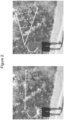
- Figure 2 schematically depicts an arrangement for achieving gaze determination
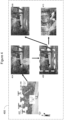
- Figure 3 schematically depicts stages of gaze determination according to some embodiments.
- the determination depends on images captured by the first plurality of drones 102, so the second plurality of drones 108 is omitted from Figure 2 , for simplicity.
- the view on the left of Figure 2 indicates image capture by two drones at different positions and orientations.
- Face detection can be carried out by, for example, a state-of-the-art, DNN-based face detection method, trained to localize the face area (indicated by dashed oval A in Figure 2 ) in images, and to estimate the degree of head rotation in each image.
- eye detection can be carried out using any one of various well-known techniques that typically localize a pair of eyes (as described below) in each image, taking the estimated head rotation into account; and finally gaze detection may be determined, which may be defined in terms of the target's field of view (a 2D indication limited by lines B - B' is shown in the view on the right of Figure 2 ) at the moment of image capture.
- Figure 3 shows examples of how eye detection and subsequent gaze determination may be achieved.
- a 2D eye "region of interest" 302 may be defined, and the irises 304 and whites 306 of the eyes may be identified within the region of interest.
- the difference in the center positions of irises and whites may be used in (for example) a DNN regression scheme to yield a 2D estimate of an eye rotation vector relevant to that single image.
- synchronized images from more than one camera in the swarm may be processed, applying a technique such as multi-view triangulation, which uses known camera poses to ultimately yield a 3D gaze determination, indicating the target's field of view (partly defined by vector u and angular spread ⁇ in the diagram at bottom right of Figure 3 ).
- a technique such as multi-view triangulation, which uses known camera poses to ultimately yield a 3D gaze determination, indicating the target's field of view (partly defined by vector u and angular spread ⁇ in the diagram at bottom right of Figure 3 ).
- Figure 4 schematically illustrates a method 400 of multi-view imaging according to some embodiments.
- the left-most part of the figure shows a view 402 of elements of system 100, described above with regard to Figure 1 .
- pluralities of images are captured and processed by the gaze positioning swarm, and other pluralities of images are captured by the first-person view swarm, while the gaze positioning swarm, optionally in collaboration with the first person view swarm, tracks the target's movements. All this occurs during the filming stage of the method, which may occur in any required outdoor or indoor environment.
- the next method stage is post-processing, which may occur at a studio or other convenient location, online or offline.
- post-processing may occur at a studio or other convenient location, online or offline.
- a first plurality of images has been captured by the gaze positioning swarm, enabling suitable drone camera posing for the capture of a second plurality of images by the first-person view swarm.
- Well known image processing techniques may be applied to the second plurality of images to create a composite pseudo-3D image 404, clearly including the view seen by target 106, but also showing part of the target's upper body, as the drone cameras capturing the images must have been slightly behind and above the target, capturing views of the target in each image.
- Well known image processing techniques may be used to remove the target from image 404 to yield image 406, and then to crop that image as desired to more closely represent the view actually seen by the target, i.e. the desired first-person view 408.
- a sequence of such views is generated from images captured over a significant period of time and action by the target, to provide a realistic immersive movie experience for the viewer. Images may be switched between "traditional" views showing the target (or actor) and first-person views of that target (or actor). An interactive experience may be provided to the viewer, offering the option of time-freezing for free view.
- images such as that shown at 410 may be generated for game and content developers.
- images 410 ordered in time and following a subject's trajectory, allow game designers to guide the player moving along the subject's route and showing the "real scene" in first-person-view.
- a content provider could also use the collection of images for other VR applications beyond game development or filming.
- the post processing stage of the method may include either one or both of automatic frame-to-frame gaze direction smoothing and automatic frame-by-frame FPV generation given the 3D gaze direction.
- FIG. 5 is a flowchart of a method 500 for multi-view imaging according to some embodiments.
- a first plurality of gaze positioning (GP) drone cameras on GP drones capture a first plurality of images of a moving target. As discussed above, the cameras are positioned and oriented such that each image includes an eye region showing at least one complete eye in the target's face.
- these images are analyzed to calculate the target's head pose and gaze, using techniques such as those described above, and the results of the calculations are transmitted to a second plurality of drones, the first-person view (FPV) drones.
- the FPV drones adjust their poses (positions and orientations) as necessary in the light of the received data.
- cameras on the FPV drones capture a plurality of images of the environment beyond the target. In general, at least some of these "FPV” images will include partial views of the target.
- post-processing of the "FPV” images is carried out, to generate a composite first-person view of the environment using techniques as described above to "remove” the target.
- Method 500 illustrates a simple case, where only one set of images is captured by each swarm of drones, and a single first-person view is generated.
- a time sequence involving a large number of sets of images will be involved, to generate a sequence of image frames for a "movie" experience rather than a single frame for a static one-shot view.
- the illustrated method may readily be extended to cover these cases, without departing from the spirit or scope of the invention.
- Embodiments described herein provide various benefits in systems and methods for multi-view imaging.
- embodiments enable first-person view generation of environments as seen by a moving target without requiring detailed prior knowledge of the target's path of movement or action, and with minimal demands on the target, as no camera or associated hardware is either worn by or in contact with the target.
- separating the operations of determining head pose and gaze from that of capturing high quality images of the environment enables optimizing drone and drone resources.
- the embodiments described above lend themselves to automated, real-time control of multiple cameras, in many cases making use of distributed control among the drones themselves. Computational demands during the filming process are modest, being limited to head pose and gaze determination without requiring scene analysis or object recognition, with processing of the images to be used to make up the final product being reserved for a post-processing stage.
- routines of particular embodiments including C, C++, Java, assembly language, etc.
- Different programming techniques can be employed such as procedural or object oriented.
- the routines can execute on a single processing device or multiple processors. Although the steps, operations, or computations may be presented in a specific order, this order may be changed in different particular embodiments. In some particular embodiments, multiple steps shown as sequential in this specification can be performed at the same time.
- Particular embodiments may be implemented in a computer-readable storage medium for use by or in connection with the instruction execution system, apparatus, system, or device.
- Particular embodiments can be implemented in the form of control logic in software or hardware or a combination of both.
- the control logic when executed by one or more processors, may be operable to perform that which is described in particular embodiments.
- Particular embodiments may be implemented by using a programmed general purpose digital computer, by using application specific integrated circuits, programmable logic devices, field programmable gate arrays, optical, chemical, biological, quantum or nanoengineered systems, components and mechanisms may be used.
- the functions of particular embodiments can be achieved by any means as is known in the art.
- Distributed, networked systems, components, and/or circuits can be used.
- Communication, or transfer, of data may be wired, wireless, or by any other means.
- a “processor” includes any suitable hardware and/or software system, mechanism or component that processes data, signals or other information.
- a processor can include a system with a general-purpose central processing unit, multiple processing units, dedicated circuitry for achieving functionality, or other systems. Processing need not be limited to a geographic location, or have temporal limitations. For example, a processor can perform its functions in "real time,” “offline,” in a “batch mode,” etc. Portions of processing can be performed at different times and at different locations, by different (or the same) processing systems. Examples of processing systems can include servers, clients, end user devices, routers, switches, networked storage, etc.
- a computer may be any processor in communication with a memory.
- the memory may be any suitable processor-readable storage medium, such as random-access memory (RAM), read-only memory (ROM), magnetic or optical disk, or other non-transitory media suitable for storing instructions for execution by the processor.
Landscapes
- Engineering & Computer Science (AREA)
- Physics & Mathematics (AREA)
- General Physics & Mathematics (AREA)
- Theoretical Computer Science (AREA)
- Aviation & Aerospace Engineering (AREA)
- General Engineering & Computer Science (AREA)
- Multimedia (AREA)
- Automation & Control Theory (AREA)
- Radar, Positioning & Navigation (AREA)
- Remote Sensing (AREA)
- Signal Processing (AREA)
- Human Computer Interaction (AREA)
- Computer Vision & Pattern Recognition (AREA)
- Studio Devices (AREA)
- Image Analysis (AREA)
- Control Of Position, Course, Altitude, Or Attitude Of Moving Bodies (AREA)
- Image Processing (AREA)
Claims (15)
- Système d'imagerie à vues multiples d'un environnement dans lequel se déplace une cible (106), le système comprenant :une première pluralité de drones (102), chaque drone étant équipé d'une caméra de drone (104) ; etune seconde pluralité de drones (108), chaque drone étant équipé d'une caméra de drone (110) ;dans lequel la première pluralité de drones (102) est configurée pour se déplacer afin de suivre le déplacement de la cible (106), en étant positionnée devant la cible (106) de telle sorte qu'une première pluralité d'images correspondantes du visage de la cible (106) est capturée par les caméras de drone (104) de la première pluralité de drones (102) ;dans lequel la cible (106) est caractérisée par une posture de la tête et un regard variables dans le temps ;dans lequel la première pluralité de drones (102) :est configurée pour réaliser des déterminations en temps réel de la posture de la tête et du regard de la cible (106), sur la base de la première pluralité d'images capturées et des relations spatiales entre les postures de la première pluralité de caméras de drone (104) ; etest configurée pour transmettre les déterminations de la posture de la tête et du regard à la seconde pluralité de drones (108) ;dans lequel la seconde pluralité de drones (108) est configurée pour se déplacer afin de suivre le déplacement de la cible (106), en étant positionnée à proximité de la cible (106), avec des postures de caméra de drone (104) déterminées, au moins en partie, par les déterminations de la posture de la tête et du regard reçues de la première pluralité de drones (102), de telle sorte que les caméras de drone (110) de la seconde pluralité de drones (108) capturent une deuxième pluralité d'images de parties de l'environnement en face de la cible (106) ; etdans lequel le post-traitement de la deuxième pluralité d'images permet de générer une vue à la première personne représentative d'une vue de l'environnement observée par la cible (106) à un moment correspondant à la capture de la première pluralité d'images.
- Système selon la revendication 1,
dans lequel des postures de la première pluralité de caméras de drone (104) sont configurées pour être ajustées selon les déterminations de la posture de la tête et du regard, de telle sorte que :une troisième pluralité d'images du visage de la cible (106) est capturée par des caméras de la première pluralité de drones (102) ; etla première pluralité de drones (102) est configurée pour réaliser des déterminations révisées en temps réel de la posture de la tête et du regard de la cible (106), sur la base de la troisième pluralité d'images capturées et des relations spatiales entre les postures ajustées de la première pluralité de caméras de drone (104), et transmettre les déterminations révisées en temps réel à la seconde pluralité de drones (108) ;dans lequel la seconde pluralité de drones (108) est configurée pour se déplacer afin de continuer à suivre un déplacement de la cible (106), en révisant des postures de caméras de drone (110) de la seconde pluralité de drones (108) déterminées, au moins en partie, par les déterminations révisées en temps réel de la posture de la tête et du regard reçues de la première pluralité de drones (102), de telle sorte que les caméras de drone (110) de la seconde pluralité de drones (108) capturent une quatrième pluralité d'images de parties de l'environnement en face de la cible (106) ; etdans lequel le post-traitement de la quatrième pluralité d'images permet de générer une vue à la première personne représentative d'une vue de l'environnement observée par la cible (106) à un moment correspondant à la capture de la troisième pluralité d'images. - Système selon la revendication 1,dans lequel les première et seconde pluralités de drones comportent respectivement des premier et second drones de référence, caractérisé par des première et seconde postures de référence ; etdans lequel les première et seconde postures de référence caractérisent des première et seconde postures de l'essaim de drones respectivement pour les première et seconde pluralités de drones.
- Système de la revendication 1, dans lequel, dans au moins l'une parmi les première et seconde pluralités de drones, des postures de tous les drones sont déterminées, au moins en partie, par un dispositif de commande d'essaim de drones basé au sol (112).
- Système selon la revendication 4, dans lequel, pour au moins l'une parmi les première et seconde pluralités de drones, le dispositif de commande d'essaim de drones basé au sol (112) est configuré pour envoyer soit i) à chacun des drones de cette pluralité une instruction de posture spécifique au drone correspondant ; soit ii) une pluralité d'instructions de posture à un drone guide dans cette pluralité, ce drone leader répondant en communiquant, directement ou indirectement, avec chaque autre drone de la pluralité, de telle sorte que chaque drone de la pluralité reçoit une instruction de posture correspondante spécifique au drone.
- Système selon la revendication 1, dans lequel la première pluralité de drones (102) est configurée pour déterminer une posture de la tête et du regard par :traitement de chaque image capturée dans la première pluralité d'images pour réussir la détection de visage et des yeux ; ettraitement d'une combinaison d'images capturées dans la première pluralité d'images pour réussir la détermination de la posture de la tête et du regard.
- Système selon la revendication 1, dans lequel le champ de vision d'au moins l'une parmi les caméras de drone (110) de la seconde pluralité de drones (108), permettant la capture d'images dans la deuxième pluralité d'images de parties de l'environnement devant la cible (106), est plus grand que le champ de vision anticipé de la cible (106).
- Procédé selon la revendication 1, dans lequel le post-traitement comprend :le lissage automatique de la direction du regard image par image pour déterminer une direction du regard estimée en 3D ; etla génération automatique d'une vue à la première personne, image par image, sur la base de la direction estimée du regard en 3D.
- Système selon la revendication 1, dans lequel, dans au moins l'une parmi les première et seconde pluralités de drones (102, 108), chaque caméra de drone (104, 110) est fixée ou positionnée dans un drone correspondant (102, 108) de telle sorte qu'une posture caractérisant ce drone détermine entièrement une posture de la caméra de drone (104, 110).
- Système selon la revendication 1,dans lequel des caractéristiques de la première pluralité de drones (102) comportent la petite taille, le faible poids et la grande maniabilité ;dans lequel des caractéristiques de la seconde pluralité de drones (108) comportent la stabilité du mouvement commandé ; etdans lequel des caractéristiques des caméras de drone (110) dans la seconde pluralité de drones (108) comportent une qualité d'image élevée sur de grands champs de vision.
- Procédé d'imagerie à vues multiples d'un environnement dans lequel se déplace une cible (106), le procédé comprenant :le fonctionnement d'une première pluralité de caméras de drone (104) sur une première pluralité de drones (102) pour capturer une première pluralité d'images de la cible (106), les drones se déplaçant pour suivre le déplacement de la cible (106) tout en étant positionnés devant la cible (106) de telle sorte que la première pluralité d'images comporte des images du visage de la cible (106), dans lequel la cible (106) est caractérisé par une posture de la tête et du regard variables dans le temps ;la réalisation de déterminations en temps réel de la posture de la tête et du regard de la cible (106), sur la base de la première pluralité d'images capturées et des relations spatiales entre les postures de la première pluralité de caméras de drone (104) ;la transmission des déterminations de la posture de la tête et du regard de la première pluralité de drones (102) à une seconde pluralité de drones (108) positionnés à proximité de la cible (106), chaque drone étant équipé d'une caméra de drone (110) ;l'ajustement de postures de la seconde pluralité de drones (108) pour répondre à la détermination de la posture de la tête et du regard transmise, si nécessaire pour suivre le déplacement de la cible (106) ;l'ajustement de postures des caméras de drone (110) sur la seconde pluralité de drones (108) et le fonctionnement des caméras de drone (110) de la seconde pluralité de drones (108) pour capturer une deuxième pluralité d'images de parties de l'environnement en face de la cible (106) ; etle post-traitement de la deuxième pluralité d'images pour générer une vue à la première personne représentative d'une vue de l'environnement observée par la cible (106) à un moment correspondant à la capture de la première pluralité d'images.
- Procédé selon la revendication 11, comprenant en outre :
après que des déterminations de la posture de la tête et du regard sont réalisées par la première pluralité de drones (102), l'ajustement de postures de la première pluralité de drones (102) et des caméras de drone (104) selon les déterminations, et le fonctionnement de la première pluralité de caméras de drone (104) de telle sorte que :une troisième pluralité d'images du visage de la cible (106) est capturée par la première pluralité de caméras du drone (104) ;des déterminations révisées en temps réel de la posture de la tête et du regard de la cible (106), sur la base de la troisième pluralité d'images capturées et des relations spatiales entre des postures ajustées de la première pluralité de caméras de drone (104), sont réalisées par la première pluralité de drones (102) ; etles déterminations révisées en temps réel de la posture de la tête et du regard sont transmises à la seconde pluralité de drones (108) ;dans lequel la seconde pluralité de drones (108) se déplace pour continuer à suivre le déplacement de la cible (106), en révisant des postures des caméras de drone (110) de la seconde pluralité de drones (108) selon, au moins en partie, les déterminations révisées en temps réel de la posture de la tête et du regard reçues de la première pluralité de drones (102), de telle sorte que les caméras de drone (110) de la seconde pluralité de drones (108) capturent une quatrième pluralité d'images de parties de l'environnement en face de la cible (106) ; etdans lequel le post-traitement de la quatrième pluralité d'images permet de générer une vue à la première personne représentative d'une vue de l'environnement observée par la cible (106) à un moment correspondant à la capture de la troisième pluralité d'images. - Procédé selon la revendication 11, dans lequel, dans au moins l'une parmi les premières et secondes pluralités de drones, des postures de tous les drones sont déterminées, au moins en partie, par un dispositif de commande d'essaim de drones basé au sol (112).
- Procédé selon la revendication 13, dans lequel, pour au moins l'une parmi les première et seconde pluralités de drones, le dispositif de commande d'essaim de drones basé au sol (112) envoie à chaque drone de cette pluralité une instruction de posture correspondante spécifique au drone.
- Procédé selon la revendication 13, dans lequel, pour au moins l'une parmi les première et seconde pluralités de drones, le dispositif de commande d'essaim de drones basé au sol (112) envoie une pluralité de commandes de posture à un drone guide dans cette pluralité, ce drone guide répondant en communiquant, directement ou indirectement, avec chaque autre drone de la pluralité, de telle sorte que chaque drone de la pluralité reçoit une instruction de posture correspondante spécifique au drone.
Applications Claiming Priority (2)
| Application Number | Priority Date | Filing Date | Title |
|---|---|---|---|
| US16/917,024 US11460867B2 (en) | 2020-06-30 | 2020-06-30 | System of multi-swarm drone capturing |
| PCT/US2021/039159 WO2022005903A1 (fr) | 2020-06-30 | 2021-06-25 | Système de capture à multiples drones en essaim |
Publications (3)
| Publication Number | Publication Date |
|---|---|
| EP4136618A1 EP4136618A1 (fr) | 2023-02-22 |
| EP4136618A4 EP4136618A4 (fr) | 2023-09-13 |
| EP4136618B1 true EP4136618B1 (fr) | 2025-03-26 |
Family
ID=79031882
Family Applications (1)
| Application Number | Title | Priority Date | Filing Date |
|---|---|---|---|
| EP21834430.7A Active EP4136618B1 (fr) | 2020-06-30 | 2021-06-25 | Système de capture d'images par drones en essaim |
Country Status (6)
| Country | Link |
|---|---|
| US (1) | US11460867B2 (fr) |
| EP (1) | EP4136618B1 (fr) |
| JP (1) | JP7527547B2 (fr) |
| KR (1) | KR102772392B1 (fr) |
| CN (1) | CN114930393B (fr) |
| WO (1) | WO2022005903A1 (fr) |
Families Citing this family (7)
| Publication number | Priority date | Publication date | Assignee | Title |
|---|---|---|---|---|
| GB2607351B (en) | 2021-06-04 | 2023-10-25 | Digital & Future Tech Limited | Media playback system |
| GB2616741B (en) * | 2021-06-04 | 2024-09-11 | Digital & Future Tech Limited | Camera location estimation |
| US11854410B2 (en) * | 2021-06-25 | 2023-12-26 | Tomahawk Robotics | Universal control architecture for control of unmanned systems |
| JP7632248B2 (ja) * | 2021-11-26 | 2025-02-19 | トヨタ自動車株式会社 | 車両撮影システムおよび車両撮影方法 |
| US12344409B2 (en) * | 2022-04-27 | 2025-07-01 | Snap Inc. | Fully autonomous drone flights |
| CN118942115B (zh) * | 2024-07-24 | 2025-02-18 | 台山市赛科农业技术有限公司 | 基于无人机辅助智慧养殖管理方法及系统 |
| CN119784796B (zh) * | 2024-12-31 | 2025-11-21 | 中国科学院西安光学精密机械研究所 | 基于光电探测无人机群包络特性的群分离与合并的检测算法 |
Citations (1)
| Publication number | Priority date | Publication date | Assignee | Title |
|---|---|---|---|---|
| US20190107845A1 (en) * | 2017-10-09 | 2019-04-11 | Intel Corporation | Drone clouds for video capture and creation |
Family Cites Families (27)
| Publication number | Priority date | Publication date | Assignee | Title |
|---|---|---|---|---|
| JP2007235399A (ja) | 2006-02-28 | 2007-09-13 | Matsushita Electric Ind Co Ltd | 自動撮影装置 |
| JP4389901B2 (ja) | 2006-06-22 | 2009-12-24 | 日本電気株式会社 | スポーツ競技におけるカメラ自動制御システム、カメラ自動制御方法、カメラ自動制御装置、およびプログラム |
| US7742623B1 (en) * | 2008-08-04 | 2010-06-22 | Videomining Corporation | Method and system for estimating gaze target, gaze sequence, and gaze map from video |
| US8805110B2 (en) * | 2008-08-19 | 2014-08-12 | Digimarc Corporation | Methods and systems for content processing |
| US8929877B2 (en) * | 2008-09-12 | 2015-01-06 | Digimarc Corporation | Methods and systems for content processing |
| KR101588971B1 (ko) * | 2013-11-22 | 2016-01-27 | 삼성전기주식회사 | 카메라의 촬영 방향 및 화각 제어 시스템 및 그 방법 |
| US10203762B2 (en) * | 2014-03-11 | 2019-02-12 | Magic Leap, Inc. | Methods and systems for creating virtual and augmented reality |
| EP4250738B1 (fr) * | 2014-04-22 | 2025-12-31 | Snap-Aid Patents Ltd. | Procédé de commande d'un appareil photo d'après un traitement d'une image capturée par un autre appareil photo |
| US9547798B2 (en) * | 2014-05-20 | 2017-01-17 | State Farm Mutual Automobile Insurance Company | Gaze tracking for a vehicle operator |
| US10852838B2 (en) * | 2014-06-14 | 2020-12-01 | Magic Leap, Inc. | Methods and systems for creating virtual and augmented reality |
| KR101690502B1 (ko) * | 2015-04-07 | 2016-12-28 | (주)코아텍 | 드론을 이용한 추적 시스템 |
| KR101662032B1 (ko) * | 2015-04-28 | 2016-10-10 | 주식회사 유브이코어 | 조종사의 시선 방향과 동기화 된 uav 항공 영상 촬영 시스템 |
| US9989965B2 (en) * | 2015-08-20 | 2018-06-05 | Motionloft, Inc. | Object detection and analysis via unmanned aerial vehicle |
| KR101800680B1 (ko) * | 2016-01-06 | 2017-11-23 | 사단법인 한국드론협회 | 다목적 기능을 제공하는 드론 시스템 |
| US11017610B2 (en) * | 2016-05-18 | 2021-05-25 | Google Llc | System and method for fault detection and recovery for concurrent odometry and mapping |
| WO2018014338A1 (fr) | 2016-07-22 | 2018-01-25 | SZ DJI Technology Co., Ltd. | Systèmes et procédés de diffusion vidéo interactive uav |
| EP3499897B1 (fr) * | 2016-08-10 | 2021-05-19 | Panasonic Intellectual Property Corporation of America | Procédé de génération de travail photographique et dispositif de traitement vidéo |
| FR3058238B1 (fr) * | 2016-10-28 | 2019-01-25 | Parrot Drones | Systeme autonome de prise de vues animees par un drone avec poursuite de cible et maintien de l'angle de prise de vue de la cible. |
| US11303814B2 (en) * | 2017-11-09 | 2022-04-12 | Qualcomm Incorporated | Systems and methods for controlling a field of view |
| KR101879168B1 (ko) * | 2017-12-26 | 2018-07-18 | (주)잼투고 | 스튜디오 장비 제어 시퀀스 공유 서비스 제공 시스템 및 제공방법 |
| JP2021144260A (ja) | 2018-06-15 | 2021-09-24 | ソニーグループ株式会社 | 情報処理装置、情報処理方法、プログラム、および情報処理システム |
| EP3588249A1 (fr) * | 2018-06-26 | 2020-01-01 | Koninklijke Philips N.V. | Appareil et procédé permettant de générer des images d'une scène |
| EP3614341A1 (fr) * | 2018-08-23 | 2020-02-26 | ETH Zurich | Appareil, procédé et programme informatique permettant de détecter la forme d'un objet déformable |
| JP2020087061A (ja) | 2018-11-28 | 2020-06-04 | パナソニックIpマネジメント株式会社 | 無人移動体及び制御方法 |
| KR20200071375A (ko) * | 2018-12-11 | 2020-06-19 | 한국전자통신연구원 | 드론 카메라 제어 방법 및 장치 |
| US11756291B2 (en) * | 2018-12-18 | 2023-09-12 | Slyce Acquisition Inc. | Scene and user-input context aided visual search |
| RU2723239C1 (ru) * | 2019-07-31 | 2020-06-09 | Общество с ограниченной ответственностью "ДВИЖЕНИЕ РЕАЛЬНОСТЬ" (ООО "ДВИЖЕНИЕ РЕАЛЬНОСТЬ") | Система получения реалистичной модели местности для виртуального мира и способ ее работы |
-
2020
- 2020-06-30 US US16/917,024 patent/US11460867B2/en active Active
-
2021
- 2021-06-25 WO PCT/US2021/039159 patent/WO2022005903A1/fr not_active Ceased
- 2021-06-25 KR KR1020227021864A patent/KR102772392B1/ko active Active
- 2021-06-25 EP EP21834430.7A patent/EP4136618B1/fr active Active
- 2021-06-25 CN CN202180006348.XA patent/CN114930393B/zh active Active
- 2021-06-25 JP JP2022579696A patent/JP7527547B2/ja active Active
Patent Citations (1)
| Publication number | Priority date | Publication date | Assignee | Title |
|---|---|---|---|---|
| US20190107845A1 (en) * | 2017-10-09 | 2019-04-11 | Intel Corporation | Drone clouds for video capture and creation |
Also Published As
| Publication number | Publication date |
|---|---|
| CN114930393B (zh) | 2025-03-28 |
| EP4136618A4 (fr) | 2023-09-13 |
| CN114930393A (zh) | 2022-08-19 |
| JP2023531959A (ja) | 2023-07-26 |
| EP4136618A1 (fr) | 2023-02-22 |
| KR20220107250A (ko) | 2022-08-02 |
| US20210405661A1 (en) | 2021-12-30 |
| JP7527547B2 (ja) | 2024-08-05 |
| KR102772392B1 (ko) | 2025-02-26 |
| US11460867B2 (en) | 2022-10-04 |
| WO2022005903A1 (fr) | 2022-01-06 |
Similar Documents
| Publication | Publication Date | Title |
|---|---|---|
| US11460867B2 (en) | System of multi-swarm drone capturing | |
| Mademlis et al. | Autonomous UAV cinematography: A tutorial and a formalized shot-type taxonomy | |
| Mademlis et al. | Autonomous unmanned aerial vehicles filming in dynamic unstructured outdoor environments [applications corner] | |
| Monajjemi et al. | Hri in the sky: Creating and commanding teams of uavs with a vision-mediated gestural interface | |
| Alcántara et al. | Autonomous execution of cinematographic shots with multiple drones | |
| US12416926B2 (en) | UAV hardware architecture | |
| KR101896654B1 (ko) | 드론을 이용한 3d 영상 처리 시스템 및 방법 | |
| Milde et al. | Bioinspired event-driven collision avoidance algorithm based on optic flow | |
| US10904427B2 (en) | Coordinated cinematic drone | |
| Mademlis et al. | A multiple-UAV architecture for autonomous media production | |
| CN106973221B (zh) | 基于美学评价的无人机摄像方法和系统 | |
| CN113238583A (zh) | 一种固定翼无人机密集编队飞行与防撞控制方法 | |
| KR102823165B1 (ko) | 멀티-드론 카메라 제어 방법 | |
| Pueyo et al. | Cinempc: A fully autonomous drone cinematography system incorporating zoom, focus, pose, and scene composition | |
| US12210358B2 (en) | Autonomous orbiting method and device and uav | |
| Chen et al. | Autonomous Camera Systems: A Survey. | |
| JP7366349B2 (ja) | マルチドローンビジュアルコンテンツ取り込みシステム | |
| Karakostas et al. | UAV cinematography constraints imposed by visual target tracking | |
| Mademlis et al. | Vision-based drone control for autonomous UAV cinematography | |
| CN109688323A (zh) | 无人机视觉跟踪系统及其控制方法 | |
| KR20240064392A (ko) | 카메라가 탑재된 드론을 이용한 지상 표적 추적 방법 및 장치 | |
| Mademlis et al. | A multiple-UAV software architecture for autonomous media production | |
| Cetinsaya et al. | Camera-based adaptive line formation and dynamic leader-following optimization (calf-dlfo) for drone swarms in real-time updated digital twins | |
| Yuan et al. | Visual steering of UAV in unknown environments | |
| CN115755981A (zh) | 一种交互式的无人机自主航拍方法及装置 |
Legal Events
| Date | Code | Title | Description |
|---|---|---|---|
| STAA | Information on the status of an ep patent application or granted ep patent |
Free format text: STATUS: THE INTERNATIONAL PUBLICATION HAS BEEN MADE |
|
| PUAI | Public reference made under article 153(3) epc to a published international application that has entered the european phase |
Free format text: ORIGINAL CODE: 0009012 |
|
| STAA | Information on the status of an ep patent application or granted ep patent |
Free format text: STATUS: REQUEST FOR EXAMINATION WAS MADE |
|
| 17P | Request for examination filed |
Effective date: 20221117 |
|
| AK | Designated contracting states |
Kind code of ref document: A1 Designated state(s): AL AT BE BG CH CY CZ DE DK EE ES FI FR GB GR HR HU IE IS IT LI LT LU LV MC MK MT NL NO PL PT RO RS SE SI SK SM TR |
|
| A4 | Supplementary search report drawn up and despatched |
Effective date: 20230811 |
|
| RIC1 | Information provided on ipc code assigned before grant |
Ipc: B64U 101/30 20230101ALI20230807BHEP Ipc: H04N 23/611 20230101ALI20230807BHEP Ipc: H04N 23/661 20230101ALI20230807BHEP Ipc: H04N 23/90 20230101ALI20230807BHEP Ipc: H04N 23/695 20230101ALI20230807BHEP Ipc: G06T 7/246 20170101ALI20230807BHEP Ipc: G06T 7/73 20170101ALI20230807BHEP Ipc: G06F 3/01 20060101ALI20230807BHEP Ipc: B64D 47/08 20060101ALI20230807BHEP Ipc: B64C 39/02 20230101ALI20230807BHEP Ipc: G05D 1/00 20060101ALI20230807BHEP Ipc: G05D 1/10 20060101ALI20230807BHEP Ipc: G06T 7/55 20170101AFI20230807BHEP |
|
| DAV | Request for validation of the european patent (deleted) | ||
| DAX | Request for extension of the european patent (deleted) | ||
| STAA | Information on the status of an ep patent application or granted ep patent |
Free format text: STATUS: EXAMINATION IS IN PROGRESS |
|
| 17Q | First examination report despatched |
Effective date: 20240320 |
|
| REG | Reference to a national code |
Ref country code: DE Ref legal event code: R079 Free format text: PREVIOUS MAIN CLASS: G06T0007550000 Ipc: G05D0001000000 Ref document number: 602021028251 Country of ref document: DE |
|
| GRAP | Despatch of communication of intention to grant a patent |
Free format text: ORIGINAL CODE: EPIDOSNIGR1 |
|
| STAA | Information on the status of an ep patent application or granted ep patent |
Free format text: STATUS: GRANT OF PATENT IS INTENDED |
|
| RIC1 | Information provided on ipc code assigned before grant |
Ipc: B64U 101/30 20230101ALI20240925BHEP Ipc: H04N 23/611 20230101ALI20240925BHEP Ipc: H04N 23/661 20230101ALI20240925BHEP Ipc: H04N 23/90 20230101ALI20240925BHEP Ipc: H04N 23/695 20230101ALI20240925BHEP Ipc: G06T 7/246 20170101ALI20240925BHEP Ipc: G06T 7/73 20170101ALI20240925BHEP Ipc: G06F 3/01 20060101ALI20240925BHEP Ipc: B64D 47/08 20060101ALI20240925BHEP Ipc: B64C 39/02 20230101ALI20240925BHEP Ipc: G06T 7/55 20170101ALI20240925BHEP Ipc: G05D 1/00 20060101AFI20240925BHEP |
|
| INTG | Intention to grant announced |
Effective date: 20241028 |
|
| P01 | Opt-out of the competence of the unified patent court (upc) registered |
Free format text: CASE NUMBER: APP_63024/2024 Effective date: 20241127 |
|
| GRAS | Grant fee paid |
Free format text: ORIGINAL CODE: EPIDOSNIGR3 |
|
| GRAA | (expected) grant |
Free format text: ORIGINAL CODE: 0009210 |
|
| STAA | Information on the status of an ep patent application or granted ep patent |
Free format text: STATUS: THE PATENT HAS BEEN GRANTED |
|
| AK | Designated contracting states |
Kind code of ref document: B1 Designated state(s): AL AT BE BG CH CY CZ DE DK EE ES FI FR GB GR HR HU IE IS IT LI LT LU LV MC MK MT NL NO PL PT RO RS SE SI SK SM TR |
|
| REG | Reference to a national code |
Ref country code: GB Ref legal event code: FG4D |
|
| REG | Reference to a national code |
Ref country code: CH Ref legal event code: EP |
|
| REG | Reference to a national code |
Ref country code: DE Ref legal event code: R096 Ref document number: 602021028251 Country of ref document: DE |
|
| REG | Reference to a national code |
Ref country code: IE Ref legal event code: FG4D |
|
| REG | Reference to a national code |
Ref country code: NL Ref legal event code: FP |
|
| PGFP | Annual fee paid to national office [announced via postgrant information from national office to epo] |
Ref country code: NL Payment date: 20250520 Year of fee payment: 5 |
|
| PG25 | Lapsed in a contracting state [announced via postgrant information from national office to epo] |
Ref country code: RS Free format text: LAPSE BECAUSE OF FAILURE TO SUBMIT A TRANSLATION OF THE DESCRIPTION OR TO PAY THE FEE WITHIN THE PRESCRIBED TIME-LIMIT Effective date: 20250626 |
|
| PG25 | Lapsed in a contracting state [announced via postgrant information from national office to epo] |
Ref country code: FI Free format text: LAPSE BECAUSE OF FAILURE TO SUBMIT A TRANSLATION OF THE DESCRIPTION OR TO PAY THE FEE WITHIN THE PRESCRIBED TIME-LIMIT Effective date: 20250326 |
|
| PGFP | Annual fee paid to national office [announced via postgrant information from national office to epo] |
Ref country code: DE Payment date: 20250520 Year of fee payment: 5 |
|
| PGFP | Annual fee paid to national office [announced via postgrant information from national office to epo] |
Ref country code: GB Payment date: 20250520 Year of fee payment: 5 |
|
| REG | Reference to a national code |
Ref country code: LT Ref legal event code: MG9D |
|
| PG25 | Lapsed in a contracting state [announced via postgrant information from national office to epo] |
Ref country code: NO Free format text: LAPSE BECAUSE OF FAILURE TO SUBMIT A TRANSLATION OF THE DESCRIPTION OR TO PAY THE FEE WITHIN THE PRESCRIBED TIME-LIMIT Effective date: 20250626 |
|
| PG25 | Lapsed in a contracting state [announced via postgrant information from national office to epo] |
Ref country code: HR Free format text: LAPSE BECAUSE OF FAILURE TO SUBMIT A TRANSLATION OF THE DESCRIPTION OR TO PAY THE FEE WITHIN THE PRESCRIBED TIME-LIMIT Effective date: 20250326 |
|
| PG25 | Lapsed in a contracting state [announced via postgrant information from national office to epo] |
Ref country code: LV Free format text: LAPSE BECAUSE OF FAILURE TO SUBMIT A TRANSLATION OF THE DESCRIPTION OR TO PAY THE FEE WITHIN THE PRESCRIBED TIME-LIMIT Effective date: 20250326 |
|
| PGFP | Annual fee paid to national office [announced via postgrant information from national office to epo] |
Ref country code: FR Payment date: 20250520 Year of fee payment: 5 |
|
| PG25 | Lapsed in a contracting state [announced via postgrant information from national office to epo] |
Ref country code: BG Free format text: LAPSE BECAUSE OF FAILURE TO SUBMIT A TRANSLATION OF THE DESCRIPTION OR TO PAY THE FEE WITHIN THE PRESCRIBED TIME-LIMIT Effective date: 20250326 Ref country code: GR Free format text: LAPSE BECAUSE OF FAILURE TO SUBMIT A TRANSLATION OF THE DESCRIPTION OR TO PAY THE FEE WITHIN THE PRESCRIBED TIME-LIMIT Effective date: 20250627 |
|
| PGFP | Annual fee paid to national office [announced via postgrant information from national office to epo] |
Ref country code: AT Payment date: 20250721 Year of fee payment: 5 |
|
| PG25 | Lapsed in a contracting state [announced via postgrant information from national office to epo] |
Ref country code: SE Free format text: LAPSE BECAUSE OF FAILURE TO SUBMIT A TRANSLATION OF THE DESCRIPTION OR TO PAY THE FEE WITHIN THE PRESCRIBED TIME-LIMIT Effective date: 20250326 |
|
| REG | Reference to a national code |
Ref country code: AT Ref legal event code: MK05 Ref document number: 1779539 Country of ref document: AT Kind code of ref document: T Effective date: 20250326 |
|
| PG25 | Lapsed in a contracting state [announced via postgrant information from national office to epo] |
Ref country code: SM Free format text: LAPSE BECAUSE OF FAILURE TO SUBMIT A TRANSLATION OF THE DESCRIPTION OR TO PAY THE FEE WITHIN THE PRESCRIBED TIME-LIMIT Effective date: 20250326 |
|
| PG25 | Lapsed in a contracting state [announced via postgrant information from national office to epo] |
Ref country code: ES Free format text: LAPSE BECAUSE OF FAILURE TO SUBMIT A TRANSLATION OF THE DESCRIPTION OR TO PAY THE FEE WITHIN THE PRESCRIBED TIME-LIMIT Effective date: 20250326 Ref country code: PT Free format text: LAPSE BECAUSE OF FAILURE TO SUBMIT A TRANSLATION OF THE DESCRIPTION OR TO PAY THE FEE WITHIN THE PRESCRIBED TIME-LIMIT Effective date: 20250728 |
|
| PG25 | Lapsed in a contracting state [announced via postgrant information from national office to epo] |
Ref country code: PL Free format text: LAPSE BECAUSE OF FAILURE TO SUBMIT A TRANSLATION OF THE DESCRIPTION OR TO PAY THE FEE WITHIN THE PRESCRIBED TIME-LIMIT Effective date: 20250326 Ref country code: IT Free format text: LAPSE BECAUSE OF FAILURE TO SUBMIT A TRANSLATION OF THE DESCRIPTION OR TO PAY THE FEE WITHIN THE PRESCRIBED TIME-LIMIT Effective date: 20250326 |
|
| PG25 | Lapsed in a contracting state [announced via postgrant information from national office to epo] |
Ref country code: AT Free format text: LAPSE BECAUSE OF FAILURE TO SUBMIT A TRANSLATION OF THE DESCRIPTION OR TO PAY THE FEE WITHIN THE PRESCRIBED TIME-LIMIT Effective date: 20250326 |
|
| PG25 | Lapsed in a contracting state [announced via postgrant information from national office to epo] |
Ref country code: EE Free format text: LAPSE BECAUSE OF FAILURE TO SUBMIT A TRANSLATION OF THE DESCRIPTION OR TO PAY THE FEE WITHIN THE PRESCRIBED TIME-LIMIT Effective date: 20250326 |
|
| PG25 | Lapsed in a contracting state [announced via postgrant information from national office to epo] |
Ref country code: RO Free format text: LAPSE BECAUSE OF FAILURE TO SUBMIT A TRANSLATION OF THE DESCRIPTION OR TO PAY THE FEE WITHIN THE PRESCRIBED TIME-LIMIT Effective date: 20250326 |
|
| PG25 | Lapsed in a contracting state [announced via postgrant information from national office to epo] |
Ref country code: SK Free format text: LAPSE BECAUSE OF FAILURE TO SUBMIT A TRANSLATION OF THE DESCRIPTION OR TO PAY THE FEE WITHIN THE PRESCRIBED TIME-LIMIT Effective date: 20250326 |
|
| PG25 | Lapsed in a contracting state [announced via postgrant information from national office to epo] |
Ref country code: IS Free format text: LAPSE BECAUSE OF FAILURE TO SUBMIT A TRANSLATION OF THE DESCRIPTION OR TO PAY THE FEE WITHIN THE PRESCRIBED TIME-LIMIT Effective date: 20250726 |
|
| REG | Reference to a national code |
Ref country code: DE Ref legal event code: R097 Ref document number: 602021028251 Country of ref document: DE |
|
| PG25 | Lapsed in a contracting state [announced via postgrant information from national office to epo] |
Ref country code: DK Free format text: LAPSE BECAUSE OF FAILURE TO SUBMIT A TRANSLATION OF THE DESCRIPTION OR TO PAY THE FEE WITHIN THE PRESCRIBED TIME-LIMIT Effective date: 20250326 |
|
| PG25 | Lapsed in a contracting state [announced via postgrant information from national office to epo] |
Ref country code: CZ Free format text: LAPSE BECAUSE OF FAILURE TO SUBMIT A TRANSLATION OF THE DESCRIPTION OR TO PAY THE FEE WITHIN THE PRESCRIBED TIME-LIMIT Effective date: 20250326 |
|
| REG | Reference to a national code |
Ref country code: CH Ref legal event code: H13 Free format text: ST27 STATUS EVENT CODE: U-0-0-H10-H13 (AS PROVIDED BY THE NATIONAL OFFICE) Effective date: 20260127 |
|
| PG25 | Lapsed in a contracting state [announced via postgrant information from national office to epo] |
Ref country code: MC Free format text: LAPSE BECAUSE OF FAILURE TO SUBMIT A TRANSLATION OF THE DESCRIPTION OR TO PAY THE FEE WITHIN THE PRESCRIBED TIME-LIMIT Effective date: 20250326 |
|
| PLBE | No opposition filed within time limit |
Free format text: ORIGINAL CODE: 0009261 |
|
| STAA | Information on the status of an ep patent application or granted ep patent |
Free format text: STATUS: NO OPPOSITION FILED WITHIN TIME LIMIT |
|
| REG | Reference to a national code |
Ref country code: CH Ref legal event code: L10 Free format text: ST27 STATUS EVENT CODE: U-0-0-L10-L00 (AS PROVIDED BY THE NATIONAL OFFICE) Effective date: 20260211 |
|
| PG25 | Lapsed in a contracting state [announced via postgrant information from national office to epo] |
Ref country code: LU Free format text: LAPSE BECAUSE OF NON-PAYMENT OF DUE FEES Effective date: 20250625 |
|
| REG | Reference to a national code |
Ref country code: BE Ref legal event code: MM Effective date: 20250630 |
|
| 26N | No opposition filed |
Effective date: 20260105 |
|
| PG25 | Lapsed in a contracting state [announced via postgrant information from national office to epo] |
Ref country code: IE Free format text: LAPSE BECAUSE OF NON-PAYMENT OF DUE FEES Effective date: 20250625 |
|
| PG25 | Lapsed in a contracting state [announced via postgrant information from national office to epo] |
Ref country code: BE Free format text: LAPSE BECAUSE OF NON-PAYMENT OF DUE FEES Effective date: 20250630 |
|
| PG25 | Lapsed in a contracting state [announced via postgrant information from national office to epo] |
Ref country code: CH Free format text: LAPSE BECAUSE OF NON-PAYMENT OF DUE FEES Effective date: 20250630 |