EP4136960B1 - System und verfahren zur bestimmung einer absolutposition eines sich bewegenden elements eines handgehaltenen elektrowerkzeugs - Google Patents
System und verfahren zur bestimmung einer absolutposition eines sich bewegenden elements eines handgehaltenen elektrowerkzeugs Download PDFInfo
- Publication number
- EP4136960B1 EP4136960B1 EP21191646.5A EP21191646A EP4136960B1 EP 4136960 B1 EP4136960 B1 EP 4136960B1 EP 21191646 A EP21191646 A EP 21191646A EP 4136960 B1 EP4136960 B1 EP 4136960B1
- Authority
- EP
- European Patent Office
- Prior art keywords
- power tool
- pcb
- handheld power
- blade
- moving element
- Prior art date
- Legal status (The legal status is an assumption and is not a legal conclusion. Google has not performed a legal analysis and makes no representation as to the accuracy of the status listed.)
- Active
Links
Images




Classifications
-
- A—HUMAN NECESSITIES
- A01—AGRICULTURE; FORESTRY; ANIMAL HUSBANDRY; HUNTING; TRAPPING; FISHING
- A01G—HORTICULTURE; CULTIVATION OF VEGETABLES, FLOWERS, RICE, FRUIT, VINES, HOPS OR SEAWEED; FORESTRY; WATERING
- A01G3/00—Cutting implements specially adapted for horticultural purposes; Delimbing standing trees
- A01G3/02—Secateurs; Flower or fruit shears
- A01G3/033—Secateurs; Flower or fruit shears having motor-driven blades
- A01G3/037—Secateurs; Flower or fruit shears having motor-driven blades the driving means being an electric motor
-
- G—PHYSICS
- G01—MEASURING; TESTING
- G01D—MEASURING NOT SPECIALLY ADAPTED FOR A SPECIFIC VARIABLE; ARRANGEMENTS FOR MEASURING TWO OR MORE VARIABLES NOT COVERED IN A SINGLE OTHER SUBCLASS; TARIFF METERING APPARATUS; MEASURING OR TESTING NOT OTHERWISE PROVIDED FOR
- G01D5/00—Mechanical means for transferring the output of a sensing member; Means for converting the output of a sensing member to another variable where the form or nature of the sensing member does not constrain the means for converting; Transducers not specially adapted for a specific variable
- G01D5/12—Mechanical means for transferring the output of a sensing member; Means for converting the output of a sensing member to another variable where the form or nature of the sensing member does not constrain the means for converting; Transducers not specially adapted for a specific variable using electric or magnetic means
- G01D5/14—Mechanical means for transferring the output of a sensing member; Means for converting the output of a sensing member to another variable where the form or nature of the sensing member does not constrain the means for converting; Transducers not specially adapted for a specific variable using electric or magnetic means influencing the magnitude of a current or voltage
- G01D5/20—Mechanical means for transferring the output of a sensing member; Means for converting the output of a sensing member to another variable where the form or nature of the sensing member does not constrain the means for converting; Transducers not specially adapted for a specific variable using electric or magnetic means influencing the magnitude of a current or voltage by varying inductance, e.g. by a movable armature
- G01D5/204—Mechanical means for transferring the output of a sensing member; Means for converting the output of a sensing member to another variable where the form or nature of the sensing member does not constrain the means for converting; Transducers not specially adapted for a specific variable using electric or magnetic means influencing the magnitude of a current or voltage by varying inductance, e.g. by a movable armature by influencing the mutual induction between two or more coils
Definitions
- the expression "power tool” designates an electric or electrically powered tool.
- the tool can be electrically powered by a stand-alone power source. During its use, it is carried by a limb of the user, for example by his hand. In particular, the same limb that carries such a tool also makes it possible to control it, for example using a trigger.
- a power tool does not have a stationary position during its use, because the user moves it, for example to machine a new object or to better machine the same object. In other words, a power tool is not stationary, i.e. it does not always occupy the same position. It is therefore clear in the light of this definition that a machine such as a stationary saw, for example a table circular saw or a bench shear, does not fit into the definition of a power tool given in this context.
- the power source of such a power tool can be for example a battery or a battery pack.
- the source is usually a separate part of the tool.
- the user can carry the tool with one hand and simultaneously wear the power source on himself, for example using a backpack, a harness or a belt.
- the power source of such a power tool is in the power tool.
- a power tool includes a motor or actuator for transmitting a force to an external object on which the tool is working.
- Pruning shears, shears, pliers, presses, a portable chainsaw, a portable circular saw, a portable jigsaw, a planer, a crimper, ripper, etc. for agricultural, viticultural, arboreal, industrial, craft, textile, food, medical, etc. applications are non-limiting examples of power tools according to the invention.
- a power tool comprises a machining member and a support member for this object.
- the machining member makes it possible to machine an object and comes into direct contact with this object. It is mobile during the machining of the object and is actuated by an actuator of the power tool.
- machining indicates any operation performed on the object that makes it possible to transform it, for example to cut it, press it, slice it, plane it etc.
- the power tool is a pruner or a power pruning shears
- its movable blade is the machining member, because it allows an object, such as a branch, to be cut
- the counter blade is the support member, because it supports the branch while cutting.
- the power tool is a circular saw
- its rotary blade is the machining member, because it allows an object, such as a piece of wood, to be cut, and the tray including the passage for the blade and resting on the object during the cutting operation is the support member.
- the power tool is a plane
- its blade is the machining member, as it allows an object, such as a wooden piece, to be cut, and the plate resting on the object during the cutting operation is the support member.
- the power tool is a portable chainsaw
- its rotary chain is the machining member, because it allows an object to be cut, and the chain guide of the portable chainsaw, around which the rotary chain moves, is the support member.
- Such moving elements are all the components in the tool, whose movement allow the tool to work, for example the components of the transmission relating the actuator to the machining member, as for example and in a non-limitative way a cam, a connecting rod, a ball screw, a ball nut, the actuator, a gear, etc.
- cutting tools comprising a device for magnetic measuring the position of the mobile blade, this device comprising one or more magnets on the mobile blade and Hall effect sensors on the body of the tool, such as for example WO2005084416 , EP2550135 and EP1452280 .
- cutting tools comprising a generic magnetic sensor placed on the body of the cutting tool, allowing to measure the position a movable blade fitted with a magnet, as for example EP3225100 and EP2353366 .
- the document RU2743368 describes a portable power tool in which the movement of the blade is carried out with a lighter and less noisy transmission system.
- a first magnetizing coil is energized by creating a magnetic flux passing through a magnetic housing.
- the magnetic flux is divided into a working magnetic flux passing through a magnetic sleeve and a first non-magnetic sleeve, a magnetic flux passing through a first non-magnetic insert, and a magnetic flux passing along the first magnetization coil. Due to the working magnetic flux, an electromagnetic force occurs which moves the armature and therefore the blade to the left ( Figure 3 ). On energizing a second magnetizing coil an electromagnetic force occurs which moves armature and hence blade to the right ( Figure 5 ), for similar reasons.
- the described system does not determine the absolute position of the moving elements.
- the document EP1738140 describes an inductive position sensor for detecting a position of a movable coupling element.
- the sensor comprises a transmitter coil and a receiver coil including two loops, the receiver coil generating a receive signal when the transmitter coil is excited by an alternating current source.
- the movable coupling element modifies the inductive coupling between the transmitting coil and the receiving coil so that the receive signal is sensitive to the position of the coupling element.
- the main application of this sensor is for detecting the position of throttle pedal in an automotive vehicle.
- those known systems for determining the position of an element do not determine this position in a robust way, as they are sensible to perturbations.
- those known systems for determining the position of an element do not determine this position in a precise way, as the precision is in the order of some millimetres around the sensor position and are barely sensitive further than a tens of millimetres.
- An aim of the present invention is the provision of a system for determining the position of a moving element of an handheld power tool, that overcomes the shortcomings and limitations of the state of the art.
- Another aim of the invention is the provision of a system for determining the position of a moving element of an handheld power tool, wherein the fabrication of such handheld power tool is simpler with regard to known solutions.
- Another aim of the invention is the provision of a system for determining the position of a moving element of an handheld power tool, wherein the determination of this position is less sensible to perturbations with regard to known solutions.
- Another aim of the invention is the provision of a system for determining the position of a moving element of an handheld power tool, wherein the determination of this position is more precise with regard to known solutions.
- these aims are attained by the object of the attached claims, and especially by the system for determining the position of a moving element of an handheld power tool and by the method for determining the position of a moving element of an handheld power tool according to the independent claims.
- the modification of the magnetic flux is related (at least) to a change in mutual inductance between the excitation coil and the measuring coil. If the moving element is made at least in part of an electrically conductive material, the modification of the magnetic flux is related the presence of Eddy currents (Foucault's currents), which constitute losses.
- the system comprises also a computing module, arranged to determine an absolute position of this moving element based on this (modified) magnetic flux.
- the measuring coil is an open circuit and this magnetic flux modifies an (induced) voltage in the measuring coil, for example a voltage between two electrical terminals of the measuring coil.
- the computing module is arranged to determine the absolute position of this element based on this voltage.
- the measuring coil is a closed circuit and this magnetic flux modifies an (induced) current in the measuring coil.
- the computing module is arranged to determine the absolute position of this element based on this current.
- the system according to the invention does not require a magnet (or any other additional element) on the machining member of the handheld power tool. Therefore, the fabrication of such handheld power tool is simpler with regard to known solutions. Moreover, the working of the tool is not disturbed by the presence of an additional element, as a magnet, on the machining member.
- the system according to the invention allows a determination of the position of the moving element less sensible to perturbations. Tests performed by the applicant have shown that the system is more robust and reliable than known solutions.
- the system according to the invention allows a determination of the position of the moving element more precise with regard to known solutions. Tests performed by the applicant have shown that this precision is in the order of micro-meters.
- the handheld power tool comprises a machining member and a support member.
- the actuator is connected to the machining member, so as to move the machining member with regard to the support member.
- this moving element is at least a part of the machining member, or this element is connected to the machining member, so that once the machining member is moved, the element is also moved. This embodiment allows therefore to determine the absolute position of (at least a part of) the machining member of the handheld power tool.
- the handheld power tool is a power pruning shears comprising a movable blade, this moving element is at least a part of the movable blade, or this element is connected to the movable blade, so that once the movable blade is moved, the element is also moved.
- This embodiment allows therefore to determine the absolute position of (at least a part of) the movable blade of the power pruning shears.
- the handheld power tool comprises a trigger arranged to be pressed by the user, so as to move the machining member with regard to the support member.
- the moving element is at least a part of this trigger or this element is connected to the trigger, so that once the trigger is moved, the element is also moved. This embodiment allows therefore to determine the absolute position of (at least a part of) the trigger of the power tool.
- the handheld power tool comprises a Printed Circuit Board ("PCB” in the following), wherein this PCB comprises the excitation coil and the measuring coil(s).
- PCB Printed Circuit Board
- the element moves on a trajectory defining a form and the PCB has a shape comprising this form. For example, if the element moves on a C-shaped trajectory, and the PCB will have a C-shaped form.
- the element moves on a trajectory defining a form and the excitation coil has a shape comprising this form.
- the excitation coil will have a C-shaped form.
- the system comprises two measuring coils.
- the absolute position of the moving element is proportional to the second harmonic of the measured signal.
- each of the measuring coils has a shape having a period, wherein the measuring coils are offset by a quarter of this period.
- a half of this period is substantially equal to a dimension of the moving element, e.g. a width of the moving element.
- the handheld power tool comprises an electrically insulator element between the body of the handheld power tool and the PCB, so as to electrically isolate the PCB from the body.
- a power pruning shears In the following description given by way of example, reference will be made, for reasons of simplicity, to a power pruning shears.
- the invention is not limited to such an instrument.
- the disclosure is also not limited to agriculture, but also includes, for example, shears, pliers, presses, chainsaws, portable circular saws, portable jigsaws, planers, crimpers, rippers, etc. for agricultural, viticultural, arboreal, industrial, craft, textile, food, medical, etc. applications.
- the disclosure is also not limited to this moving element, but applies also to other moving elements of the tools, for example the trigger, any component of the transmission relating the actuator to the machining member, as for example and in a non-limitative way a cam, a connecting rod, a ball screw, a ball nut, the actuator, a gear, etc. or any other element of the handheld power tool, which moves with regard to the (fixed) body of the handheld power tool.
- the disclosure is also not limited to the kind of the speed (constant, accelerated, decelerated, continuous, discontinuous, etc.) of the moving element.
- FIG. 1 A schematic example of a handheld power tool 10 of the system according to the invention is illustrated in Figure 1 .
- This tool is arranged to be worn by a user, for example by a limb of the user such as a hand.
- this same hand can control the tool 10 via a trigger 3.
- the power tool 10 comprises a guard 5, a body 9, a machining member 4 and a support member 2.
- the machining member 4 makes it possible to machine an object and comes into direct contact with this object. It is mobile during the machining of the object and actuated by an actuator (not shown) of the handheld power tool 10, for example an electric motor.
- machining indicates any operation performed on the object that makes it possible to transform it, for example to cut, press, slice, plane etc.
- the support member 2 supports the object during its machining and is fixed during the machining of the object.
- the support member is not actuated by the actuator of the power tool 10. Its presence is necessary to achieve this machining.
- the support member 2 also comes into direct contact with this object during its machining.
- the power tool 10 is a power pruning shears
- its movable blade is the machining member 4, as it allows to cut an object such as a branch
- the counter blade is the support member 2 because it supports the branch during cutting.
- the power tool 10 is connected by a connection element 6, namely a cable in the example of figure 1 , to a control box 130 of the tool, placed in a support means 100 carried by the user, in the example a backpack.
- This control box 130 is connected via the connection element 7 to one or more batteries 140 in the same support means 100, and via the connection element 8 to a remote housing 160, which may comprise a display 161, and which is generally placed on a belt 170 worn by the user.
- the belt 170 is part of the backpack 100.
- the power pruner shears 10 also includes a transmission (not shown) connecting the actuator (not shown) of the power pruner shears 10 to the movable blade 4, so as to allow movement of the movable blade 4 relative to the counter blade 2.
- Non-limiting examples of transmission include a screw-to-ball/nut system, in which the screw moves with a translational movement and the nut turns with a rotational movement and/or in which the screw which is moves with a rotational motion and the nut moves with a translational motion, connecting rods, cams, etc.
- connection element in the example a bolt 90.
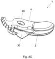
- This connection element is at least partly received by through holes of the movable blade 4 (reference 49 in Figure 4C ) and of the counter blade 2 (reference 29 in Figure 4A ), which are aligned during the superposition of the two blades ( Figure 4C ).
- the movable blade 4 is arranged to pivot relative to the counter blade 2 around an axis of rotation (not illustrated) which passes through the connection element.
- the movable blade 4 comprises a cutting part 40 and an actuating part 42, the two parts extending from the connection element 90 and forming an angle between them, of approximately 180 ° in the example illustrated in Figures 2 to 3 .
- this angle is not limitative and other different angles are possible.
- the actuating part 42 of the movable blade 4 comprises a connection element with the transmission of the electric pruning shears 10, a set of teeth 44 in the example illustrated.
- a blade actuation arm 48 connects this set of teeth 44 to the cutting part 40.
- the transmission via the set of teeth 44 and the blade actuation arm 48, causes the rotation of the movable blade 4 around its axis of rotation.
- the cutting part 40 can move away from the counter blade 2 ( Figure 3 ), thus allowing the user to insert an object to be cut into the space 60 which is created between the cutting part 40 and the counter blade 2, and then can approach to the counter blade 2 ( Figure 2 ), thus making the cut of this object.
- the cutting part 40 of the movable blade 4 in fact comprises a sharp edge 46, which allows this cut.
- the cutting part 40 of the movable blade of Figures 2 to 3 has a substantially linear shape. However, other forms can be considered, for example and in a non-limiting way a shape of a beak, slightly curved.
- the free end of the cutting part 40 in the plane of a side surface of the movable blade 4 has a greater width with respect to the width of the cutting part 40 in correspondence of the connection element 90.
- the width w of the blade actuation arm 48 is lower than the widths of the cutting part 40.
- the movable blade is not flat, in other examples (not shown) it may be flat.
- the movable blade 4 in order to determine the absolute position of the movable blade 4 with the system according to the invention, should be made at least in part of a ferromagnetic material and/or by an electrically conductive material (for example and without limitation in steel or in hardened steel).
- the counter blade 2 visible in Figure 4A , comprises a support part 20 and a fixing part 22, the two parts extending from the connection means and forming an angle between them, greater than 90° in the example illustrated on Figure 4A .
- the support part 20 allows to support an object to be cut during the cutting and at least partially comes into direct contact with this object.
- the fixing part 22 allows the counter blade 2 to be fixed to the body 9 of the power pruning shears 10, in order to make the body 9 integral with the counter blade 2.
- the fixing part 22 of the counter blade 2 comprises means for fixing the counter blade 2 with the body 9 of the power pruning shears 10, an hole 24 in the illustrated example.
- the support part 20 of the counter blade 2 of the example has a hook shape, slightly curved. However, other forms can be considered.
- the free end of the support part 20 in the plane of a side surface of the counter blade 2 has a greater width with respect to the width of the support part in correspondence of the connection element 90.
- the counter blade 2 is not flat, in other examples it may be flat.
- its side surface 27 intended to come into contact with the movable blade 4 is not flat, but includes a sap groove 21, which makes it possible to reduce the friction surface between the movable blade and the counter blade without the risk of the blades sticking, for example when cutting sap plants. It saves time and makes trimming easier by removing dirt and sap after each cutting motion.
- the sap groove 21 is the part of the counter blade 2 which rubs against the movable blade 4 during its movement. It is adjacent to another surface 23 (less thick), which does not come into contact with the movable blade 4 during its movement.
- the movable blade 4 and the counter blade can comprise (at least) a chamfer of the counter blade 2., i.e. a surface obtained by removing the edge of a blade. It is a bevel, which can be rounded, and whose function is to avoid sharp edges.
- a PCB 30 is placed between the movable blade 4 and the counter blade 2.
- the PCB 30 is sandwiched between the movable blade 4 and the counter blade 2 (cf Figures 4A to 4C ) and notably, it is sandwiched between the actuating part 42 of the movable blade 4 and the fixing part 22 of the counter blade 2.
- the thickness of the fixing part 22 of the counter blade 2 (“first thickness” in the following) is lower than the thickness of its support part 20 (“second thickness” in the following).
- the PCB 30 has a thickness which is substantially equal to the difference between the second thickness and the first thickness, so that, once the PCB 30 is placed on the fixing part 22, the surface of the PCB 30 opposite to the fixing part 22 is substantially planar with the side surface 27 of the counter blade 2, as illustrated in Figure 4B .
- the PCB 30 is placed on the surface of the movable blade 4 opposite to the surface facing the counter blade 2.
- this embodiment is less advantageous: in fact, in case of a replacement of a (used) movable blade, the PCB should be removed as well and a new calibration of the system according to the invention is necessary.
- the embodiment wherein the PCB 30 is sandwiched between the movable blade 4 and the counter blade 2 is more advantageous, as the PCB 30 can be placed once when the handheld power tool 10 is assembled, and calibrated once during or after the assembling.
- the (used) movable blade 4 can be replaced without removing the PCB 30 and without recalibrating the system according to the invention.
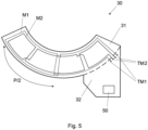
- the PCB 30 comprises a C-shaped part 31, as illustrated for example in Figure 5 .
- this C-shaped part 31 is arranged to face the blade actuating arm 48, as illustrated for example in Figures 2 to 3 .
- the PCB 30 comprises another (second) part 32, visible for example in Figure 5 , adjacent to the C-shaped part 31.
- the shape of the second part 32 is arranged to receive some electrical components, for example the computing module 50 of the invention, and it is arranged so as to render the whole system more ergonomic.
- the PCB 30 comprises only the C-shaped part 31 and the computing module 50 is placed away, for example in the body 9 of the power pruning shears 10, electrically connected to the C-shaped part 31.
- the computing module 50 it is preferred to place the computing module 50 sufficiently near to the measuring coil(s), for improving the measure quality.
- the PCB 30 comprises at least one measuring coil (two measuring coils M1 and M2 in Figure 5 ). In one embodiment, the PCB comprises (also) at least one excitation coil (one excitation coil E1 in Figure 6 ).
- the measuring coil(s) and the excitation coil(s) can be on the same face of the PCB or on two opposite faces.
- the measuring coil(s) and the excitation coil(s) are one the same face of the PCB 30, in particular on the C-shaped part 31 of the PCB 30.
- the measuring coil(s) M1, M2 of Figure 5 have been illustrated without the excitation coil E1 and the excitation coil E1 of Figure 6 has been illustrated without the measuring coil(s) M1, M2.
- the excitation coil(s) E1 is(are) arranged to conduct an alternating excitation current, wherein the alternating excitation current generates a magnetic flux traversing two measuring coils M1, M2.
- the excitation coil E1 comprises electrical terminals TE1, visible on Figure 6 , arranged to be connected to an alternating current source.
- the alternating current source belongs to the computing module 50.
- the moving element (the movable blade 4 in the example of the Figures) is arranged to be moved by the actuator of the power pruning shears with regard to the body 9 of the power pruning shears, and the moving of this element modifies the magnetic flux.
- the system comprises a computing module 50, arranged to determine an absolute position of this element based on the (modified) magnetic flux.
- the modification of the magnetic flux is related (at least) to a change in mutual inductance between the excitation coil E1 and the measuring coil(s) M1, M2. If the moving element is made at least in part of an electrically conductive material the modification of the magnetic flux is related the presence of Eddy currents, which constitute losses.
- the moving element is made of material which is both ferromagnetic and electrically conductive.
- the measuring coil(s) is(are) an open circuit and this magnetic flux modifies an (induced) voltage in the measuring coil, for example a voltage between two electrical terminals TM1, TM2 of each measuring coil M1, M2.
- the computing module 50 is arranged to determine the absolute position of this element based on this voltage.
- those electrical terminals TM1, TM2 are electrically connected to the computing module 5.
- the excitation coil E1 has a shape comprising this form, as illustrated in Figure 6 .
- the system comprises two measuring coils M1, M2, as illustrated in Figure 5 .
- the absolute position of the moving element is proportional to the second harmonic of the sum of the measured signals.
- each of the measuring coils M1, M2 has the same shape having a period P.
- this shape is a squared wave.
- other periodic wave can be imagined, as a sinusoidal wave, a pulsed wave, etc.
- the measuring coils M1, M2 are (mechanically) offset by a quarter of this period (P/4).
- the blade actuating arm 48 completely couples with the measuring coil M1 at one end of the C-shaped portion 31 of the PCB 30 (for example the left end in Figure 5 ), have a zero totalized flux when the blade actuating arm 48 is at the centre of the C-shaped portion 31 and the blade actuating arm 48 completely couples with the measuring coil M2 at the other end of the C-shaped portion 31 of the PCB 30 (for example the right end in Figure 5 ).
- the number of (measuring and excitation) coils is limited, in another embodiments this number can be higher, so as to exploit this redundance.
- the PCB comprises different layers and the (measuring and excitation) coils can be distributed in those layers.
- the part of the PCB 30 which is not supported by the counter blade 2 (or by the support member) is supported by the body 9 of the handheld power tool 10, i.e. it enters into contact with this body 9.
- the body 9 is (at least partially) electrically conductive.
- the handheld power tool 10 comprises an electrically insulator element 60, arranged to be sandwiched between the body 9 of the handheld power tool and the PCB 30 (in particular its first part 31 not supported by the support member 2), so as to electrically isolate the PCB 30 from the body 9.
- An example of this electrically insulator element 60 is illustrated in Figure 7 .
- the electrically insulator element 60 has a shape comprising this form.
- the element the electrically insulator element 60 has a C-shaped form.
- the surface of the electrically insulator element 60 facing the body 9 of the handheld power tool 10 and/or the surface of the electrically insulator element 60 facing the PCB 30 comprises an adhesive layer, so as to attach it to the body 9 respectively to the PCB 30.
- the PCB 30 comprises a user interface, comprising e.g. LEDs and/or buttons.
- the (excitation and measuring) coils, the computing module and the moving element form a (linear or rotative) variable differential transformer (LVDT or RVDT), wherein the moving element of the handheld power tool 10 is part of this transformer.
- LVDT variable differential transformer
- the computing module is the integrated circuit LX3301A commercialized by Microchip / Microsemi.
Landscapes
- Life Sciences & Earth Sciences (AREA)
- Physics & Mathematics (AREA)
- General Physics & Mathematics (AREA)
- Biodiversity & Conservation Biology (AREA)
- Ecology (AREA)
- Forests & Forestry (AREA)
- Environmental Sciences (AREA)
- Scissors And Nippers (AREA)
Claims (13)
- System zum Bestimmen einer absoluten Position eines beweglichen Elements (3, 4) eines handgehaltenen Elektrowerkzeugs (10), wobei das System umfasst:- das besagte handgehaltene Elektrowerkzeug (10), umfassend:- einen Körper (9), mit:- einem Aktuator,- einer Erregerspule (E1), welche dazu eingerichtet ist, einen alternierenden Erregerstrom zu leiten, worin der alternierende Erregerstrom einen magnetischen Fluss erzeugt, welcher zwei Messspulen (M1, M2) durchquert,- den besagten Messspulen (M1, M2), worin die besagten Messspulen (M1, M2) eine Form mit einer Periode (P) aufweisen, worin die besagten Messspulen um ein Viertel der besagten Periode (P) versetzt sind,- ein bewegliches Element (3, 4), welches zumindest teilweise aus einem ferromagnetischen Material und/oder einem elektrisch leitfähigen Material besteht, wobei das besagte Element derart angeordnet ist, um von einem Benutzer und/oder vom besagten Aktuator in Bezug auf den Körper (9) bewegt zu werden, worin das Bewegen des besagten Elements (3, 4) den besagten magnetischen Fluss verändert,worin das System umfasst:- ein Rechenmodul (50), welches dazu eingerichtet ist, eine absolute Position des besagten beweglichen Elements (3, 4) basierend auf dem besagten magnetischen Fluss zu bestimmen.
- System gemäss Anspruch 1, worin das besagte handgehaltene Elektrowerkzeug (10) umfasst- ein Bearbeitungselement (4),- ein Trägerelement (2),worin der Aktuator mit dem Bearbeitungselement (4) verbunden ist, um das Bearbeitungselement (4) in Bezug auf das Trägerelement (2) zu bewegen, worin das besagte bewegliche Element zumindest ein Teil des besagten Bearbeitungselements (4) ist.
- System gemäss Anspruch 1, worin das besagte handgehaltene Elektrowerkzeug (10) eine elektrische Gartenschere mit einer beweglichen Schneide (4) ist, worin das besagte bewegliche Element zumindest ein Teil der besagten beweglichen Schneide (4) ist.
- System gemäss Anspruch 1, worin das besagte handgehaltene Elektrowerkzeug (10) umfasst:- ein Bearbeitungselement (4),- ein Trägerelement (2),worin der Aktuator mit dem Bearbeitungselement (4) verbunden ist, um das Bearbeitungselement (4) in Bezug auf das Trägerelement (2) zu bewegen,- einen Auslöser (3), welcher derart angeordnet ist, um vom Benutzer gedrückt zu werden, um das Bearbeitungselement (4) in Bezug auf das Trägerelement (2) zu bewegen, worin das besagte bewegliche Element zumindest ein Teil des besagten Auslösers (3) ist.
- System gemäss einem der Ansprüche 1 bis 4, worin das besagte handgehaltene Elektrowerkzeug (10) eine Leiterplatte (30) umfasst, worin die besagte Leiterplatte (30) die besagte Erregerspule (E1) und die besagte Messspule (M1, M2) umfasst.
- System gemäss Anspruch 5, worin die besagte Leiterplatte (30) das besagte Rechenmodul (50) umfasst.
- System gemäss einem der Ansprüche 5 bis 6, worin sich das besagte Element (3, 4) auf einer Laufbahn bewegt, welche eine Form definiert, und worin die Leiterplatte (30) eine Form aufweist, welche diese Form umfasst.
- System gemäss Anspruch 1, worin die Hälfte der Periode (P) im Wesentlichen gleich einer Abmessung des besagten beweglichen Elements (4) ist, z. B. einer Breite des besagten Elements.
- System gemäss Anspruch 1, worin das handgehaltene Elektrowerkzeug (10) eine elektrische Gartenschere ist, worin die Hälfte der besagten Periode (P) im Wesentlichen gleich einer Breite eines Schneidebetätigungsarms (48) einer beweglichen Schneide (4) der elektrischen Gartenschere ist.
- System gemäss einem der Ansprüche 5 bis 7, worin das besagte handgehaltene Elektrowerkzeug (10) ein elektrisch isolierendes Element (60) zwischen dem Körper (9) des handgehaltenen Elektrowerkzeugs (10) und der Leiterplatte (30) umfasst, um die besagte Leiterplatte (30) elektrisch vom besagten Körper (9) zu isolieren.
- System gemäss Anspruch 10, worin das besagte elektrisch isolierende Element (60) zumindest teilweise aus einem nicht elektrisch leitenden und ferromagnetischen Material, beispielsweise Ferrit, besteht.
- System gemäss einem der Ansprüche 5 bis 7, worin die besagte Leiterplatte zwischen einer beweglichen Schneide (4) und einer Gegenschneide (2) eingeschlossen ist.
- Verfahren zum Bestimmen einer absoluten Position eines beweglichen Elements (3, 4) eines handgehaltenen Elektrowerkzeugs (10), wobei das bewegliche Element (3, 4) zumindest teilweise aus einem ferromagnetischen Material und/oder aus einem elektrisch leitfähigen Material besteht, worin das handgehaltene Elektrowerkzeug (10) einen Körper (9) umfasst, wobei der besagte Körper (9) einen Aktuator umfasst, worin das besagte Verfahren umfasst:- Leiten eines alternierenden Erregerstroms durch eine Erregerspule (E1),- Durchfliessen eines durch den besagten alternierenden Erregerstrom erzeugten magnetischen Flusses in zwei Messspulen (M1, M2), worin die besagten Messspulen (M1, M2) eine Form mit einer Periode (P) aufweisen, worin die besagten Messspulen um ein Viertel der besagten Periode (P) versetzt sind,- Bewegen des besagten Elements (3, 4) durch einen Benutzer und/oder durch den besagten Aktuator in Bezug auf den Körper (9), worin das Bewegen des besagten Elements (3, 4) den besagten magnetischen Fluss verändert,- Bestimmen einer absoluten Position des besagten Elements (3, 4) basierend auf dem besagten magnetischen Fluss durch ein Rechenmodul (50).
Priority Applications (1)
| Application Number | Priority Date | Filing Date | Title |
|---|---|---|---|
| EP21191646.5A EP4136960B1 (de) | 2021-08-17 | 2021-08-17 | System und verfahren zur bestimmung einer absolutposition eines sich bewegenden elements eines handgehaltenen elektrowerkzeugs |
Applications Claiming Priority (1)
| Application Number | Priority Date | Filing Date | Title |
|---|---|---|---|
| EP21191646.5A EP4136960B1 (de) | 2021-08-17 | 2021-08-17 | System und verfahren zur bestimmung einer absolutposition eines sich bewegenden elements eines handgehaltenen elektrowerkzeugs |
Publications (2)
| Publication Number | Publication Date |
|---|---|
| EP4136960A1 EP4136960A1 (de) | 2023-02-22 |
| EP4136960B1 true EP4136960B1 (de) | 2025-04-09 |
Family
ID=77367313
Family Applications (1)
| Application Number | Title | Priority Date | Filing Date |
|---|---|---|---|
| EP21191646.5A Active EP4136960B1 (de) | 2021-08-17 | 2021-08-17 | System und verfahren zur bestimmung einer absolutposition eines sich bewegenden elements eines handgehaltenen elektrowerkzeugs |
Country Status (1)
| Country | Link |
|---|---|
| EP (1) | EP4136960B1 (de) |
Family Cites Families (9)
| Publication number | Priority date | Publication date | Assignee | Title |
|---|---|---|---|---|
| ES1050293Y (es) | 2001-10-25 | 2002-07-01 | Hispaes S A | Util de corte motorizado con dispositivo de automatizacion del corte. |
| ES2245217B1 (es) * | 2004-03-04 | 2006-08-01 | Josep Gurri Molins | Util de corte portatil accionado mecanicamente. |
| US7276897B2 (en) * | 2004-04-09 | 2007-10-02 | Ksr International Co. | Inductive position sensor |
| ES2382279B1 (es) * | 2009-08-10 | 2013-05-08 | Bellota Herramientas S.A.U | Dispositivo electrico de corte |
| FR2955734B1 (fr) | 2010-02-03 | 2012-03-09 | Infaco | Secateur pour la taille des vegetaux |
| FR2957834B1 (fr) | 2010-03-24 | 2012-03-09 | Infaco | Dispositif de controle positionnel de deux elements l'un par rapport a l'autre tel que lames d'outils de coupe du genre secateur et outil de coupe le comportant |
| US9872440B2 (en) | 2012-05-04 | 2018-01-23 | Felco Motion Sa | Handheld power tool |
| FR3049427B1 (fr) | 2016-03-31 | 2018-04-27 | Innovation Fabrication Commercialisation Infaco | Outil de coupe motorise electroportatif, de type secateur |
| RU2743368C1 (ru) * | 2020-08-11 | 2021-02-17 | федеральное государственное бюджетное образовательное учреждение высшего образования "Ставропольский государственный аграрный университет" | Ножовочная пила |
-
2021
- 2021-08-17 EP EP21191646.5A patent/EP4136960B1/de active Active
Also Published As
| Publication number | Publication date |
|---|---|
| EP4136960A1 (de) | 2023-02-22 |
Similar Documents
| Publication | Publication Date | Title |
|---|---|---|
| KR20130017087A (ko) | 전지 가위-유형의 절단 공구와 같은 두 요소의 상대 배치를 제어하기 위한 장치 및 이를 포함한 절단 공구 | |
| EP3484663B1 (de) | Auslöseranordnung | |
| RU2470263C2 (ru) | Портативный электроинструмент, снабженный устройством для определения относительного положения между двумя органами инструмента, по меньшей мере один из которых выполнен подвижным | |
| US20150059186A1 (en) | Hand-held power tool information device | |
| US11784538B2 (en) | Power tool user interfaces | |
| US6776076B2 (en) | Angle gauge | |
| DE50107060D1 (de) | Vorrichtung zur berührungslosen wegmessung, insbesondere zur stellungs- und bewegungserfassung | |
| EP1002218B1 (de) | Magnetischer wegsensor | |
| GB2466383A (en) | Power tool with means for determining the type of material of the workpiece | |
| WO2021043558A1 (de) | Werkzeugmaschinenvorrichtung | |
| EP4136960B1 (de) | System und verfahren zur bestimmung einer absolutposition eines sich bewegenden elements eines handgehaltenen elektrowerkzeugs | |
| US10663113B2 (en) | Safety system and method for a portable electrical tool | |
| EP4025388A1 (de) | Werkzeugmaschinenvorrichtung | |
| EP2621682B1 (de) | Ortungsvorrichtung | |
| EP0015731B1 (de) | Verbesserte Handsägeführung | |
| EP2621681B1 (de) | Handwerkzeugmaschinenvorrichtung | |
| EP3411173B1 (de) | Haltekrafterfassung für einen magnetischen bohrständer | |
| WO1998033041A1 (en) | Magnetic displacement detector and carburetor opening detector | |
| CN110756868B (zh) | 铣削加工系统及方法 | |
| JPH0225729B2 (de) | ||
| EP2621656B1 (de) | Ortungsvorrichtung | |
| US20230249326A1 (en) | Method for Detecting a Kickback or a Breakthrough of a Machine Tool with an Oscillating Output Movement, Device, and Machine Tool Comprising the Device | |
| KR20070108590A (ko) | 자동 시편 절단장치 | |
| JPH06143097A (ja) | 測定補助工具およびそれを用いる加工方法 | |
| CN120080193A (zh) | 切割模块、加工设备和加工设备的控制方法 |
Legal Events
| Date | Code | Title | Description |
|---|---|---|---|
| PUAI | Public reference made under article 153(3) epc to a published international application that has entered the european phase |
Free format text: ORIGINAL CODE: 0009012 |
|
| STAA | Information on the status of an ep patent application or granted ep patent |
Free format text: STATUS: THE APPLICATION HAS BEEN PUBLISHED |
|
| AK | Designated contracting states |
Kind code of ref document: A1 Designated state(s): AL AT BE BG CH CY CZ DE DK EE ES FI FR GB GR HR HU IE IS IT LI LT LU LV MC MK MT NL NO PL PT RO RS SE SI SK SM TR |
|
| STAA | Information on the status of an ep patent application or granted ep patent |
Free format text: STATUS: REQUEST FOR EXAMINATION WAS MADE |
|
| 17P | Request for examination filed |
Effective date: 20230815 |
|
| RBV | Designated contracting states (corrected) |
Designated state(s): AL AT BE BG CH CY CZ DE DK EE ES FI FR GB GR HR HU IE IS IT LI LT LU LV MC MK MT NL NO PL PT RO RS SE SI SK SM TR |
|
| GRAP | Despatch of communication of intention to grant a patent |
Free format text: ORIGINAL CODE: EPIDOSNIGR1 |
|
| STAA | Information on the status of an ep patent application or granted ep patent |
Free format text: STATUS: GRANT OF PATENT IS INTENDED |
|
| RIC1 | Information provided on ipc code assigned before grant |
Ipc: G01D 5/22 20060101ALI20241127BHEP Ipc: A01G 3/037 20060101AFI20241127BHEP |
|
| INTG | Intention to grant announced |
Effective date: 20241216 |
|
| GRAS | Grant fee paid |
Free format text: ORIGINAL CODE: EPIDOSNIGR3 |
|
| GRAA | (expected) grant |
Free format text: ORIGINAL CODE: 0009210 |
|
| STAA | Information on the status of an ep patent application or granted ep patent |
Free format text: STATUS: THE PATENT HAS BEEN GRANTED |
|
| AK | Designated contracting states |
Kind code of ref document: B1 Designated state(s): AL AT BE BG CH CY CZ DE DK EE ES FI FR GB GR HR HU IE IS IT LI LT LU LV MC MK MT NL NO PL PT RO RS SE SI SK SM TR |
|
| REG | Reference to a national code |
Ref country code: GB Ref legal event code: FG4D |
|
| REG | Reference to a national code |
Ref country code: CH Ref legal event code: EP |
|
| REG | Reference to a national code |
Ref country code: DE Ref legal event code: R096 Ref document number: 602021028805 Country of ref document: DE |
|
| REG | Reference to a national code |
Ref country code: IE Ref legal event code: FG4D |
|
| REG | Reference to a national code |
Ref country code: NL Ref legal event code: MP Effective date: 20250409 |
|
| PG25 | Lapsed in a contracting state [announced via postgrant information from national office to epo] |
Ref country code: NL Free format text: LAPSE BECAUSE OF FAILURE TO SUBMIT A TRANSLATION OF THE DESCRIPTION OR TO PAY THE FEE WITHIN THE PRESCRIBED TIME-LIMIT Effective date: 20250409 |
|
| REG | Reference to a national code |
Ref country code: AT Ref legal event code: MK05 Ref document number: 1782641 Country of ref document: AT Kind code of ref document: T Effective date: 20250409 |
|
| PG25 | Lapsed in a contracting state [announced via postgrant information from national office to epo] |
Ref country code: PT Free format text: LAPSE BECAUSE OF FAILURE TO SUBMIT A TRANSLATION OF THE DESCRIPTION OR TO PAY THE FEE WITHIN THE PRESCRIBED TIME-LIMIT Effective date: 20250811 Ref country code: FI Free format text: LAPSE BECAUSE OF FAILURE TO SUBMIT A TRANSLATION OF THE DESCRIPTION OR TO PAY THE FEE WITHIN THE PRESCRIBED TIME-LIMIT Effective date: 20250409 Ref country code: ES Free format text: LAPSE BECAUSE OF FAILURE TO SUBMIT A TRANSLATION OF THE DESCRIPTION OR TO PAY THE FEE WITHIN THE PRESCRIBED TIME-LIMIT Effective date: 20250409 |
|
| PGFP | Annual fee paid to national office [announced via postgrant information from national office to epo] |
Ref country code: DE Payment date: 20250820 Year of fee payment: 5 |
|
| REG | Reference to a national code |
Ref country code: LT Ref legal event code: MG9D |
|
| PG25 | Lapsed in a contracting state [announced via postgrant information from national office to epo] |
Ref country code: NO Free format text: LAPSE BECAUSE OF FAILURE TO SUBMIT A TRANSLATION OF THE DESCRIPTION OR TO PAY THE FEE WITHIN THE PRESCRIBED TIME-LIMIT Effective date: 20250709 Ref country code: GR Free format text: LAPSE BECAUSE OF FAILURE TO SUBMIT A TRANSLATION OF THE DESCRIPTION OR TO PAY THE FEE WITHIN THE PRESCRIBED TIME-LIMIT Effective date: 20250710 |
|
| PG25 | Lapsed in a contracting state [announced via postgrant information from national office to epo] |
Ref country code: PL Free format text: LAPSE BECAUSE OF FAILURE TO SUBMIT A TRANSLATION OF THE DESCRIPTION OR TO PAY THE FEE WITHIN THE PRESCRIBED TIME-LIMIT Effective date: 20250409 |
|
| PG25 | Lapsed in a contracting state [announced via postgrant information from national office to epo] |
Ref country code: BG Free format text: LAPSE BECAUSE OF FAILURE TO SUBMIT A TRANSLATION OF THE DESCRIPTION OR TO PAY THE FEE WITHIN THE PRESCRIBED TIME-LIMIT Effective date: 20250409 |
|
| PGFP | Annual fee paid to national office [announced via postgrant information from national office to epo] |
Ref country code: BE Payment date: 20250820 Year of fee payment: 5 Ref country code: GB Payment date: 20250820 Year of fee payment: 5 |
|
| PG25 | Lapsed in a contracting state [announced via postgrant information from national office to epo] |
Ref country code: HR Free format text: LAPSE BECAUSE OF FAILURE TO SUBMIT A TRANSLATION OF THE DESCRIPTION OR TO PAY THE FEE WITHIN THE PRESCRIBED TIME-LIMIT Effective date: 20250409 |
|
| PG25 | Lapsed in a contracting state [announced via postgrant information from national office to epo] |
Ref country code: AT Free format text: LAPSE BECAUSE OF FAILURE TO SUBMIT A TRANSLATION OF THE DESCRIPTION OR TO PAY THE FEE WITHIN THE PRESCRIBED TIME-LIMIT Effective date: 20250409 |
|
| PGFP | Annual fee paid to national office [announced via postgrant information from national office to epo] |
Ref country code: FR Payment date: 20250828 Year of fee payment: 5 |
|
| PGFP | Annual fee paid to national office [announced via postgrant information from national office to epo] |
Ref country code: CH Payment date: 20250901 Year of fee payment: 5 |
|
| PG25 | Lapsed in a contracting state [announced via postgrant information from national office to epo] |
Ref country code: RS Free format text: LAPSE BECAUSE OF FAILURE TO SUBMIT A TRANSLATION OF THE DESCRIPTION OR TO PAY THE FEE WITHIN THE PRESCRIBED TIME-LIMIT Effective date: 20250709 |
|
| PG25 | Lapsed in a contracting state [announced via postgrant information from national office to epo] |
Ref country code: IS Free format text: LAPSE BECAUSE OF FAILURE TO SUBMIT A TRANSLATION OF THE DESCRIPTION OR TO PAY THE FEE WITHIN THE PRESCRIBED TIME-LIMIT Effective date: 20250809 |
|
| PG25 | Lapsed in a contracting state [announced via postgrant information from national office to epo] |
Ref country code: LV Free format text: LAPSE BECAUSE OF FAILURE TO SUBMIT A TRANSLATION OF THE DESCRIPTION OR TO PAY THE FEE WITHIN THE PRESCRIBED TIME-LIMIT Effective date: 20250409 |
|
| REG | Reference to a national code |
Ref country code: DE Ref legal event code: R097 Ref document number: 602021028805 Country of ref document: DE |
|
| PG25 | Lapsed in a contracting state [announced via postgrant information from national office to epo] |
Ref country code: DK Free format text: LAPSE BECAUSE OF FAILURE TO SUBMIT A TRANSLATION OF THE DESCRIPTION OR TO PAY THE FEE WITHIN THE PRESCRIBED TIME-LIMIT Effective date: 20250409 Ref country code: SM Free format text: LAPSE BECAUSE OF FAILURE TO SUBMIT A TRANSLATION OF THE DESCRIPTION OR TO PAY THE FEE WITHIN THE PRESCRIBED TIME-LIMIT Effective date: 20250409 |
|
| PG25 | Lapsed in a contracting state [announced via postgrant information from national office to epo] |
Ref country code: CZ Free format text: LAPSE BECAUSE OF FAILURE TO SUBMIT A TRANSLATION OF THE DESCRIPTION OR TO PAY THE FEE WITHIN THE PRESCRIBED TIME-LIMIT Effective date: 20250409 |
|
| PG25 | Lapsed in a contracting state [announced via postgrant information from national office to epo] |
Ref country code: EE Free format text: LAPSE BECAUSE OF FAILURE TO SUBMIT A TRANSLATION OF THE DESCRIPTION OR TO PAY THE FEE WITHIN THE PRESCRIBED TIME-LIMIT Effective date: 20250409 |
|
| PG25 | Lapsed in a contracting state [announced via postgrant information from national office to epo] |
Ref country code: SK Free format text: LAPSE BECAUSE OF FAILURE TO SUBMIT A TRANSLATION OF THE DESCRIPTION OR TO PAY THE FEE WITHIN THE PRESCRIBED TIME-LIMIT Effective date: 20250409 |
|
| PG25 | Lapsed in a contracting state [announced via postgrant information from national office to epo] |
Ref country code: IT Free format text: LAPSE BECAUSE OF FAILURE TO SUBMIT A TRANSLATION OF THE DESCRIPTION OR TO PAY THE FEE WITHIN THE PRESCRIBED TIME-LIMIT Effective date: 20250409 |
|
| PG25 | Lapsed in a contracting state [announced via postgrant information from national office to epo] |
Ref country code: RO Free format text: LAPSE BECAUSE OF FAILURE TO SUBMIT A TRANSLATION OF THE DESCRIPTION OR TO PAY THE FEE WITHIN THE PRESCRIBED TIME-LIMIT Effective date: 20250409 |
|
| PLBE | No opposition filed within time limit |
Free format text: ORIGINAL CODE: 0009261 |
|
| STAA | Information on the status of an ep patent application or granted ep patent |
Free format text: STATUS: NO OPPOSITION FILED WITHIN TIME LIMIT |
|
| REG | Reference to a national code |
Ref country code: CH Ref legal event code: L10 Free format text: ST27 STATUS EVENT CODE: U-0-0-L10-L00 (AS PROVIDED BY THE NATIONAL OFFICE) Effective date: 20260218 |
|
| 26N | No opposition filed |
Effective date: 20260112 |
|
| PG25 | Lapsed in a contracting state [announced via postgrant information from national office to epo] |
Ref country code: MC Free format text: LAPSE BECAUSE OF FAILURE TO SUBMIT A TRANSLATION OF THE DESCRIPTION OR TO PAY THE FEE WITHIN THE PRESCRIBED TIME-LIMIT Effective date: 20250409 |
|
| PG25 | Lapsed in a contracting state [announced via postgrant information from national office to epo] |
Ref country code: LU Free format text: LAPSE BECAUSE OF NON-PAYMENT OF DUE FEES Effective date: 20250817 |