EP4137360B1 - Remorque porte-voiture - Google Patents
Remorque porte-voiture Download PDFInfo
- Publication number
- EP4137360B1 EP4137360B1 EP21191929.5A EP21191929A EP4137360B1 EP 4137360 B1 EP4137360 B1 EP 4137360B1 EP 21191929 A EP21191929 A EP 21191929A EP 4137360 B1 EP4137360 B1 EP 4137360B1
- Authority
- EP
- European Patent Office
- Prior art keywords
- car transporter
- support
- rail vehicle
- transporter
- Prior art date
- Legal status (The legal status is an assumption and is not a legal conclusion. Google has not performed a legal analysis and makes no representation as to the accuracy of the status listed.)
- Active
Links
Images





Classifications
-
- B—PERFORMING OPERATIONS; TRANSPORTING
- B60—VEHICLES IN GENERAL
- B60P—VEHICLES ADAPTED FOR LOAD TRANSPORTATION OR TO TRANSPORT, TO CARRY, OR TO COMPRISE SPECIAL LOADS OR OBJECTS
- B60P1/00—Vehicles predominantly for transporting loads and modified to facilitate loading, consolidating the load, or unloading
- B60P1/43—Vehicles predominantly for transporting loads and modified to facilitate loading, consolidating the load, or unloading using a loading ramp mounted on the vehicle
- B60P1/433—Vehicles predominantly for transporting loads and modified to facilitate loading, consolidating the load, or unloading using a loading ramp mounted on the vehicle the loading floor or a part thereof being movable to form the ramp
-
- B—PERFORMING OPERATIONS; TRANSPORTING
- B60—VEHICLES IN GENERAL
- B60P—VEHICLES ADAPTED FOR LOAD TRANSPORTATION OR TO TRANSPORT, TO CARRY, OR TO COMPRISE SPECIAL LOADS OR OBJECTS
- B60P3/00—Vehicles adapted to transport, to carry or to comprise special loads or objects
- B60P3/06—Vehicles adapted to transport, to carry or to comprise special loads or objects for carrying vehicles
- B60P3/07—Vehicles adapted to transport, to carry or to comprise special loads or objects for carrying vehicles for carrying road vehicles
-
- B—PERFORMING OPERATIONS; TRANSPORTING
- B61—RAILWAYS
- B61D—BODY DETAILS OR KINDS OF RAILWAY VEHICLES
- B61D3/00—Wagons or vans
- B61D3/16—Wagons or vans adapted for carrying special loads
- B61D3/18—Wagons or vans adapted for carrying special loads for vehicles
-
- B—PERFORMING OPERATIONS; TRANSPORTING
- B61—RAILWAYS
- B61D—BODY DETAILS OR KINDS OF RAILWAY VEHICLES
- B61D47/00—Loading or unloading devices combined with vehicles, e.g. loading platforms, doors convertible into loading and unloading ramps
- B61D47/005—Loading or unloading devices combined with road vehicles carrying wagons, e.g. ramps, turntables, lifting means
-
- B—PERFORMING OPERATIONS; TRANSPORTING
- B62—LAND VEHICLES FOR TRAVELLING OTHERWISE THAN ON RAILS
- B62D—MOTOR VEHICLES; TRAILERS
- B62D21/00—Understructures, i.e. chassis frame on which a vehicle body may be mounted
- B62D21/09—Means for mounting load bearing surfaces
Definitions
- the invention relates to a car transporter for transporting vehicles with the features of the preamble of claim 1, a method for loading a car transporter and an arrangement comprising a car transporter for transporting vehicles and a rail vehicle, in particular a pocket wagon with a pocket.
- Car transporters or vehicle transporters known in the prior art usually have a chassis with at least one axle with wheels for driving on a roadway and a loading area for loading with cargo in the form of at least one vehicle.
- a chassis with at least one axle with wheels for driving on a roadway
- a loading area for loading with cargo in the form of at least one vehicle.
- restrictions on the maximum permissible height and length must be observed for transport on public roads. Such restrictions can apply to the basic length of the unloaded car transporter, as well as to the length of a loaded car transporter. It is known to arrange at least part of the loading area at a rear end of the car transporter.
- the loading area can extend behind the axle of the car transporter at the rear, viewed in a longitudinal direction of the car transporter, and this part of the loading area can also be designed to be movable, in particular in the form of a movable loading and unloading ramp.
- this part of the loading area of a car transporter When such a loading area of a car transporter is loaded, there may be a loading overhang in which part of the load can extend beyond the basic length of the loaded car transporter.
- the car transporter is usually loaded onto a suitable rail vehicle, for example in the form of a railway flat wagon, in particular a low-floor wagon.
- a suitable rail vehicle for example in the form of a railway flat wagon, in particular a low-floor wagon.
- the car transporters which are often used as Semi-trailers are driven onto and parked on the rail vehicles together with tractor units, which takes a lot of time.
- this type of loading also results in a high centre of gravity, which can have a negative impact on the handling of the loaded rail vehicle.
- restrictions on the maximum permissible length and, in particular, height that apply to transport by rail must also be observed.
- the vehicles loaded on the car transporter can be loaded individually onto a suitable railway wagon, which is also very time-consuming, as the vehicles have to be driven off the car transporter and onto special railway wagons.
- From the DE 866913 C is a vehicle transporter with a movable loading area.
- the object of the invention is to provide a car transporter for transporting vehicles, a method for loading a car transporter and an arrangement comprising a car transporter and a rail vehicle, in which the disadvantages discussed above do not occur.
- a car transporter for transporting vehicles according to claim 1, a method for loading such a car transporter and an arrangement of such a car transporter and a rail vehicle.
- a car transporter is basically suitable for transporting cargo in the form of vehicles, especially passenger cars.
- the car transporter has a chassis with at least one axle with wheels for driving directly on a roadway. Multi-axle versions are possible.
- the car transporter has at least one loading area for loading with cargo in the form of at least one vehicle.
- the loading area has, at least in sections, a support or supports for wheels of at least one axle of a vehicle to be loaded.
- the car transporter can be designed as a single-story or multi-story vehicle, with loading areas having different height offsets.
- the at least one loading area has a support at a rear end of the car transporter, which is movable relative to a frame of the car transporter between at least a first and a second position.
- the different positions of this support can relate to a longitudinal offset and/or a height offset relative to the frame.
- the support arranged at the rear end can be liftable between at least a first and a second position.
- the at least Two different positions may differ in terms of the usable space at the rear below the support.
- the support in the first position can advantageously be suitable for loading the support.
- the support in the first position can be lowered relative to the frame and, if necessary, extend the loading area as a loading ramp for vehicles to drive directly onto it.
- the support In the second position, the support can be raised relative to the frame and have an increased usable space at the rear below the support. This can, for example, create more ground clearance below the support.
- a rear end of the support is arranged in a longitudinal direction of the car transporter in at least one of the at least two positions behind the axle.
- a rear end of the support can form the rearmost point - in relation to the basic length of the car transporter - in at least one of the at least two positions in a longitudinal direction of the car transporter.
- a load loaded on this support of the car transporter can, if necessary, extend beyond the basic length of the loaded car transporter. For such a loading overhang, a part of the load can form the rearmost point of a loaded car transporter - in relation to the total length of the car transporter.
- a maximum permissible basic length for a car transporter can be up to 16.5 meters without a load. With a loading overhang of up to 1.5 meters, a maximum permissible total length of a loaded car transporter can be up to 18 meters.
- the lower loading area can have the support.
- the car transporter can basically be designed as a trailer that can be moved by a tractor.
- the car transporter can have a kingpin and be designed as a semi-trailer.
- the car transporter To load the car transporter onto a rail vehicle, the car transporter has gripping edges for a lifting device.
- Immediately craneable cargo refers to cargo which itself has gripping edges for a lifting device, i.e. which can essentially be loaded by a lifting device without any additional aids.
- Cargo that cannot be directly craned refers to a cargo that does not have any gripping edges for a lifting device.
- Such cargo can be made craneable using aids if necessary.
- this is disadvantageous in that it involves additional time and additional logistical effort and additional weight of the aids that are usually loaded together with the cargo and remain with it during transport.
- the car transporter Because the car transporter has gripping edges for a lifting device, it can be loaded directly from a lifting device onto a rail vehicle, thus avoiding the disadvantages of a car transporter that cannot be directly craned.
- the lifting device can be a loading crane that is lowered to the height of the gripping edges and that uses grippers to engage gripping edges arranged on the car transporter in order to lift the car transporter.
- the gripping edges can basically be designed in the shape of a bow and arranged on the frame, and/or designed as recesses in the frame.
- the car transporter has at least one pair of gripping edges for the lifting device, wherein the gripping edges are arranged on the frame of the car transporter.
- the gripping edges can be arranged on opposite sides of longitudinal beams of the frame.
- the gripping edges can be arranged at least in sections above a level of a loading area of the car transporter.
- the car transporter can have at least two pairs of gripping edges for the lifting device, wherein at least two of the pairs of gripping edges are arranged on the frame of the car transporter essentially centrally around the middle of the basic length of the car transporter, as seen in a longitudinal direction of the car transporter.
- the center of gravity of an unloaded and an evenly loaded car transporter can be located essentially centrally to the basic length of the car transporter. If the gripping edges on the frame are arranged essentially centrally around the middle of the basic length of the car transporter, a lifting device can engage the gripping edges with minimal moment loading of the lifting device.
- the support can be pivotable relative to the frame of the car transporter between at least a first and a second position and/or can be displaced in a height position. Pivoting and/or moving can generally be carried out by a drive, in particular a hydraulic cylinder.
- the support can be pivotably mounted on the frame about a horizontal pivot axis running transversely to a longitudinal extension of the car transporter.
- the support can in particular be mounted on at least one pivot arm pivotably mounted on the frame.
- the pivot arm can preferably be designed to be variable in length.
- the support is designed to be adjustable in height
- the support can be mounted in a guide on the frame.
- the wheels of at least one axle of a loaded vehicle can be placed on the support.
- the support can be made using a perforated sheet or a wheel frame, which can have a frame-shaped structure for partially accommodating a wheel.
- the support can be designed to be variable in length.
- the support can have at least one foldable and/or extendable partial area, whereby the extension of the support can be foldable or telescopic.
- the position of the support relative to the frame can be adjusted, for example, by means of a pivoting and length-adjustable support arm for mounting the support. This can also be used to create a length-adjustable support.
- the length of the support arm can be changed manually or by a drive.
- the rail vehicle can be a flat wagon or, in particular, a pocket wagon.
- Pocket wagons known in the state of the art have a pocket for the transport of loads that can be craned directly or indirectly.
- Pocket wagons of this type can have a pocket with a longitudinal extension of around 11 metres, into which cargo weighing up to 44.5 tonnes can be loaded.
- the cargo is usually arranged at least partially in the pocket.
- the rail vehicle in the form of a pocket wagon can have a frame with two bogies arranged at the front and two longitudinal beams which connect the bogies to one another.
- a lowered loading area can be arranged between the bogies and the longitudinal beams, the pocket being formed by the frame and the loading area.
- the method may comprise at least the following steps: Firstly, a car transporter can be made available on a roadway by directly driving onto it using a chassis of the car transporter.
- the car transporter Before lifting and moving, the car transporter can be uncoupled from the tractor unit.
- the car transporter After uncoupling the car transporter from the tractor unit, the car transporter can be supported on the road, for example by means of length-adjustable support legs.
- a loading area of the car transporter can be loaded with at least one vehicle. This can preferably be done by driving directly onto it. At least one axle of a vehicle can be placed on a support arranged at a rear end of the car transporter and movable, in particular specifiable, between at least a first and a second position relative to a frame of the car transporter. As mentioned, a permissible basic length for the car transporter can be exceeded by a loading overhang. When loading, the support can be in the appropriate first position.
- the support arranged at a rear end of the car transporter can be moved, in particular lifted, from the first to the second position.
- the second position of the support can be suitable for transport on the rail vehicle.
- the support can be raised relative to the frame in the second position and have an enlarged usable space at the rear below the support, whereby a collision with interfering contours on the rail vehicle can be avoided during loading.
- the car transporter which may be loaded, can be lifted directly using a lifting device, whereby the lifting device engages in or on the gripping edges of the car transporter for the lifting process.
- the car transporter can be moved over the rail vehicle using the lifting device.
- the car transporter can be lowered onto the rail vehicle. If this has not been done before lifting or lowering, the support can be moved from the first to the second position by placing the car transporter on the rail vehicle.
- the car transporter can be at least partially inserted into a pocket of the pocket wagon when the car transporter is set down.
- the car transporter can be arranged with at least part of the loading area within a longitudinal extension in the pockets.
- Part of the loading area, in particular at least part of the support can be arranged outside the pocket due to the usable space below the support being enlarged in the second position of the support and can protrude beyond the pocket.
- cargo loaded on the car transporter can be arranged partially outside the pocket in the longitudinal extension of the pocket.
- the rail vehicle can be unloaded in the reverse order of the process steps.
- the car transporter can be placed directly onto the rail vehicle, in particular into a pocket wagon, by means of the gripping edges arranged thereon and, if necessary, can be arranged at least partially in the pocket of the pocket wagon.
- the height of the gripping edges on the frame of the car transporter can be selected so that, when the car transporter is arranged in the pocket, they are located above the level of the upper edge of the pocket.
- a part of the loading area in particular at least a part of the support, can be arranged outside the pocket due to the usable space below the support being enlarged in the second position of the support and can protrude beyond the pocket.
- cargo loaded on the car transporter can be arranged partially outside the pocket in the longitudinal extension of the pocket.
- a car transporter loaded into a pocket can be secured using a height-adjustable support bracket on the pocket trolley to lock a kingpin of the car transporter.
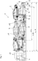
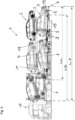
- the Figures 1 and 2 show a first embodiment of a car transporter 1 loaded with vehicles 2 with a chassis with at least one axle 3 with wheels for direct travel on a roadway 4, wherein the car transporter 1 is coupled to a tractor 18.
- the car transporter 1 is multi-story and has a total longitudinal extension LA.
- a maximum permissible basic length LG of the car transporter 1 can be up to 16.5 meters without a load, for example.
- a maximum permissible total longitudinal extension LA of a loaded car transporter 1 can be up to 18 meters, for example.
- the car transporter 1 has a lower loading area 5 which has a longitudinal extension LL.
- the loading area 5 has a support 7 at a rear end 6 of the car transporter 1, which is pivotably mounted about a horizontal pivot axis S on the frame 8 of the car transporter 1 and which is movable relative to the frame 8 between at least a first and a second position.
- the support 7 can be moved between the first and the second position in a corresponding method step.
- a rear end 9 of the support 7 is arranged behind the axle 3 in a longitudinal direction of the car transporter 1.
- the pivot axis S is also arranged behind the axle 3 in a longitudinal direction of the car transporter 1.
- the rear end 9 of the support 7 forms the rear end 6 of the car transporter 1.
- the support 7 is in the first position which is suitable for loading the support 7.
- the vehicle can be loaded, for example, by driving up a ramp (not shown).
- At least one axle 15 of a vehicle 2 is parked on the support 7.
- the support 7 is in the second position, which is suitable for transport on the rail vehicle 10 (see for example Figure 5 ).
- the support 7 can be raised in the second position relative to the frame 8 by pivoting upwards about the pivot axis S and have an enlarged usable space at the rear below the support 7, whereby a collision with interfering contours present on a rail vehicle 10 can be avoided during loading.
- the car transporter 1 has gripping edges 11, 12 for a lifting device in the form of recesses on the frame 8 of the car transporter for direct loading of the car transporter 1 onto a rail vehicle 10.
- the support 7 is designed to be adjustable in length by means of an extendable partial area 13, whereby the longitudinal extent LL of the loading area 5 can be increased. This means that, for example, a permissible loading overhang can be used.
- the extendable partial area 13 is designed in the form of an exit ramp.
- the Figures 3 and 4 show a second embodiment of a car transporter 1 loaded with vehicles 2, this embodiment being different from the Figures 1 and 2 shown first embodiment by the design of the support 7 arranged at the rear end 6 of the car transporter 1.
- the Figures 3 and 4 The positions of the support 7 shown correspond essentially to those of the Figures 1 and 2 positions shown.
- the pivotable support 7 is mounted on the frame 8 via a length-adjustable pivot arm 14.
- An axle 15 of a vehicle 2 is parked on the support 7.
- the extension ramp 19 which can be extended from the frame 8, forms the rear end 6 of the car transporter 1.
- a longitudinal extension LL of the loading area 5 can be extended by the extension ramp 19.
- the extension ramp 19 can, however, represent an interfering contour, as a result of which loading the car transporter 1 onto a rail vehicle is not possible without restrictions.
- the support 7 is in the second position, which is suitable for transport on the rail vehicle 10 (see for example Figure 6 ).
- the support 7 can be raised in the second position relative to the frame 8 by pivoting the pivot arm 14 up about the pivot axis S and have an enlarged usable space at the rear below the support 7.
- the extension ramp 19 at the rear end 6 has been retracted in order to keep the space below the support 7 free.
- the rear end 9 of the support 7 forms the rear end 6 of the car transporter 1.
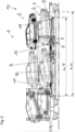
- Figure 5 shows an arrangement of a car transporter 1 according to the embodiment of Figures 3 and 4 and a rail vehicle 10 in the form of a pocket wagon with a pocket 17 which has a longitudinal extension LT.
- the car transporter 1 is arranged in the longitudinal extension and also in the vertical extension partially in the pocket 17. A part of the loading area 5, which has a larger overall longitudinal extension LL, is arranged within the longitudinal extension LT of the pocket 17.
- the car transporter 1 can be moved in corresponding process steps by a gripping edge 11, 12 of the The lifting device acting on the car transporter 1 must have been lifted and placed on the rail vehicle 10.
- a part of the loading area 5, in particular a part of the support 17, can be arranged outside the pocket 17 due to the usable space below the support 7 which is enlarged in the second position of the support 7 and can protrude beyond the pocket 17 with a rear end 9 of the support 7, which also forms the rear end of the car transporter 1.
- cargo loaded on the car transporter 1, for example in the form of the vehicles 2 can be arranged partially outside the pocket 17.
- a height of the arrangement of the gripping edges 11, 12 on the frame 8 of the car transporter 1 can be selected such that, when the car transporter 1 is arranged in the pocket 17, they are located above the level of the upper edge 20 of the pocket 17.
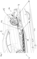
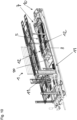
- FIGS 6 , 8 and 9 show perspective detailed views of an unloaded car transporter 1 inserted into a pocket 17 of a rail vehicle 10 designed as a pocket wagon according to the embodiment of the Figure 5
- the swiveling support 7 can be seen, which is mounted on the frame 8 via a length-adjustable swivel arm 14.
- a drive 21 is clearly provided.
- the support 7 is designed to be adjustable in length by means of the extendable section 13.
- a position of the support 7 relative to the frame 8 can be adjusted by means of the pivoting and in this design adjustable in length support arm 14, whereby effectively a length-adjustable design of the support 7 is also formed.
- a change in the length of the support arm 14 can basically be done manually or as in the design of the Figure 6 recognizable by a drive 22, here exemplified in the form of a hydraulic cylinder.
- Figure 7 shows one of the Figures 6 , 8 and 9 analogous view of a car transporter 1 inserted into a pocket 17, wherein an axle 15 of a vehicle 2 is parked on the support 7.
- Figure 10 shows a perspective view of an unloaded car transporter 1 inserted into a pocket 17 of a rail vehicle 10 designed as a pocket wagon according to the embodiment of Figure 5 .
- the height of the arrangement of the gripping edges 11, 12 on the frame 8 of the car transporter 1 can be selected such that, when the car transporter 1 is arranged in the pocket 17, they are located above the level of the upper edge of the pocket 17.
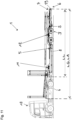
- Figure 11 shows a side view of an unloaded car transporter 1 according to the embodiment of the Figures 3 and 4
- the upper loading area and the loading areas arranged behind the cab of the tractor unit 18 are in a lowered position, as may be required for empty transport on the road.
- the car transporter By retracting the exit ramp 19 and correspondingly positioning the support 7, the car transporter has a substantially minimal longitudinal extension LA, which here corresponds to the basic length LG of the car transporter 1.
- the longitudinal extension LL of the lower loading area 5 is essentially completely located within the basic length LG of the car transporter 1.
- the loading area 5 can be equipped with the entire longitudinal extension LL can be arranged within the longitudinal extension LT of the pocket 17.
Landscapes
- Engineering & Computer Science (AREA)
- Transportation (AREA)
- Mechanical Engineering (AREA)
- Health & Medical Sciences (AREA)
- Public Health (AREA)
- Vehicle Cleaning, Maintenance, Repair, Refitting, And Outriggers (AREA)
Claims (11)
- Transporteur de voitures (1) destiné à transporter des véhicules (2), avec- un train de roulement avec au moins un essieu (3) avec des roues, destiné à circuler directement sur une chaussée (4), et- au moins une surface de chargement (5) destinée à être chargée avec au moins un véhicule (2),dans lequel l'au moins une surface de chargement (5) présente, sur une extrémité arrière (6) du transporteur de voitures (1), un appui (7), qui peut être déplacé, en particulier soulevé, entre au moins une première et une deuxième position par rapport à un châssis (8) du transporteur de voitures (1), dans lequel une extrémité côté arrière (9) de l'appui (7) est disposée derrière l'essieu (3) dans au moins une des positions dans un sens longitudinal du transporteur de voitures (1), caractérisé en ce que le transporteur de voitures (1) présente des bords de préhension (11) pour un dispositif de levage pour charger le transporteur de voitures (1) sur un véhicule sur rails (10), dans lequel le transporteur de voitures (1) présente au moins une paire de bords de préhension (11) pour le dispositif de levage et les bords de préhension (11) sont disposés sur le châssis (8) du transporteur de voitures (1).
- Transporteur de voitures selon l'une quelconque des revendications précédentes, dans lequel le transporteur de voitures (1) présente au moins deux paires de bords de préhension (11, 12) pour le dispositif de levage et au moins deux paires de bords de préhension (11, 12) sont disposées sur le châssis (8) du transporteur de voitures (1) sensiblement au centre autour du milieu de la longueur de base (LG) du transporteur de voitures.
- Transporteur de voitures selon l'une quelconque des revendications précédentes, dans lequel l'appui (7) peut être pivoté entre au moins une première et une deuxième position et/ou peut être amené dans une position en hauteur par rapport au châssis (8).
- Transporteur de voitures selon l'une quelconque des revendications précédentes, dans lequel l'appui (7) s'adapte dans la première position pour charger l'appui (7) et/ou l'appui (7) présente, côté arrière dans la deuxième position, sous l'appui (7), un espace utilisable agrandi.
- Transporteur de voitures selon l'une quelconque des revendications précédentes, dans lequel l'appui (7) est réalisé de manière variable en longueur, en particulier par au moins une zone partielle (13) dépliable et/ou extensible.
- Procédé destiné à charger un transporteur de voitures (1) selon l'une quelconque des revendications précédentes, sur un véhicule sur rails (10), en particulier sur un wagon poche, dans lequel le procédé comprend au moins les étapes de procédé suivantes :- de fourniture d'un transporteur de voitures (1) sur une chaussée (4) par circulation directe au moyen d'un train de roulement du transporteur de voitures (1) avec au moins un essieu (3) avec des roues,- éventuellement de chargement d'au moins une surface de chargement (5) du transporteur de voitures (1) avec au moins un véhicule (2), dans lequel au moins un essieu (15) d'un véhicule (2) est placé sur un appui (7) pouvant être déplacé, en particulier soulevé, entre au moins une première et une deuxième position par rapport à un châssis (8) du transporteur de voitures (1), disposé sur une extrémité côté arrière (6) du transporteur de voitures (1), dans lequel l'appui (7) se trouve dans la première position, qui est adaptée pour charger l'appui (7),- éventuellement de déplacement, en particulier de soulèvement, de l'appui (7) de la première dans la deuxième position, qui s'adapte au transport sur le véhicule sur rails (10),- de soulèvement et d'amenée du transporteur de voitures (1) - éventuellement chargé - avec un dispositif de levage au-dessus du véhicule sur rails (10), dans lequel le dispositif de levage s'engage pour l'opération de levage dans ou sur les bords de préhension (11, 12) du transporteur de voitures (1),- de dépôt du transporteur de voitures (1) sur le véhicule sur rails (10).
- Procédé destiné à charger un transporteur de voitures (1) sur un véhicule sur rails (10) selon la revendication précédente, dans lequel le véhicule sur rails (10) est réalisé sous la forme d'un wagon poche avec une poche (17), dans lequel une insertion au moins partielle du transporteur de voitures (1), en particulier une insertion au moins partielle de la surface de chargement (5), dans une poche (17) du véhicule sur rails (10) est effectuée lors du dépôt du transporteur de voitures (1) sur le véhicule sur rails (10).
- Procédé destiné à charger un transporteur de voitures (1) sur un véhicule sur rails (10) selon l'une quelconque des deux revendications précédentes, dans lequel un déplacement, en particulier un soulèvement, de l'appui (7) de la première dans la deuxième position, qui s'adapte au transport sur le véhicule sur rails (10), est effectué par un dépôt du transporteur de voitures (1) sur le véhicule sur rails (10) lorsque ceci n'est pas effectué avant le dépôt.
- Ensemble composé d'un transporteur de voitures (1) destiné au transport de véhicules (2) selon l'une quelconque des revendications 1 à 5 et d'un véhicule sur rails (10).
- Ensemble selon la revendication précédente, dans lequel le véhicule sur rails (10) est réalisé sous la forme d'un wagon poche avec une poche (17) et le transporteur de voitures (1) est disposé au moins en partie dans la poche (17).
- Ensemble selon la revendication précédente, dans lequel la poche (17) présente une extension longitudinale (LT) et au moins une partie de l'appui (7) disposé sur l'extrémité côté arrière (6) du transporteur de véhicules (1) dépasse d'une extension longitudinale (LT) de la poche (17).
Priority Applications (1)
| Application Number | Priority Date | Filing Date | Title |
|---|---|---|---|
| EP21191929.5A EP4137360B1 (fr) | 2021-08-18 | 2021-08-18 | Remorque porte-voiture |
Applications Claiming Priority (1)
| Application Number | Priority Date | Filing Date | Title |
|---|---|---|---|
| EP21191929.5A EP4137360B1 (fr) | 2021-08-18 | 2021-08-18 | Remorque porte-voiture |
Publications (3)
| Publication Number | Publication Date |
|---|---|
| EP4137360A1 EP4137360A1 (fr) | 2023-02-22 |
| EP4137360B1 true EP4137360B1 (fr) | 2024-10-30 |
| EP4137360C0 EP4137360C0 (fr) | 2024-10-30 |
Family
ID=77465808
Family Applications (1)
| Application Number | Title | Priority Date | Filing Date |
|---|---|---|---|
| EP21191929.5A Active EP4137360B1 (fr) | 2021-08-18 | 2021-08-18 | Remorque porte-voiture |
Country Status (1)
| Country | Link |
|---|---|
| EP (1) | EP4137360B1 (fr) |
Family Cites Families (4)
| Publication number | Priority date | Publication date | Assignee | Title |
|---|---|---|---|---|
| DE866913C (de) * | 1941-07-11 | 1953-02-12 | Daimler Benz Ag | Strassen- oder Schienenlastzug zur Befoerderung kleinerer Fahrzeuge |
| US3119506A (en) * | 1960-09-15 | 1964-01-28 | Motor Carrier Labor Advisory C | Side-loading transfer vehicle |
| US4789281A (en) * | 1987-07-30 | 1988-12-06 | Autohaul Industries, Inc. | Automobile hauling trailer |
| ITTO20060048A1 (it) * | 2006-01-25 | 2007-07-26 | Sitfa S P A | Sistema per il trasporto combinato di merci su ferrovia e su strada |
-
2021
- 2021-08-18 EP EP21191929.5A patent/EP4137360B1/fr active Active
Also Published As
| Publication number | Publication date |
|---|---|
| EP4137360A1 (fr) | 2023-02-22 |
| EP4137360C0 (fr) | 2024-10-30 |
Similar Documents
| Publication | Publication Date | Title |
|---|---|---|
| EP3268257B1 (fr) | Dispositif de transport levable | |
| DE69506569T2 (de) | Sattelauflieger, insbesondere zum transport von fahrzeugen und verfahren für sein verladen auf fahrzeuge und sein entladen von fahrzeugen | |
| EP3604075B1 (fr) | Dispositif porteur élevable | |
| DE69930062T2 (de) | Vorrichtung zur Handhabung eines Behälters für ein Straßenfahrzeug | |
| EP2792515B1 (fr) | Système de véhicule destiné à transporter des marchandises sur rails et sur routes, kit de rééquipement de wagon d'un système de véhicule destiné à transporter des marchandises sur rails et sur routes et procédé de rééquipement | |
| DE19823380C2 (de) | Vorrichtung zur Verringerung der Achslast eines mehrachsigen fahrbaren Teleskopkranes | |
| EP3299244B1 (fr) | Wagon de transport ferroviaire des véhicules de transport autonomes | |
| EP1927505A2 (fr) | Camion à remorque destiné au transport de véhicules, tracteur et remorque correspondants tout comme procédé destiné à la décharge de la remorque | |
| EP4137360B1 (fr) | Remorque porte-voiture | |
| DE69011518T2 (de) | Sattelanhänger. | |
| DE102008048089B4 (de) | Sattelauflieger | |
| EP3604072A1 (fr) | Dispositif porteur élevable | |
| EP3296175B1 (fr) | Procede de transport de semi-remorque | |
| DE69511671T2 (de) | Verschwenkbare Aufsattelvorrichtung auf einem Eisenbahnwagen | |
| EP0538648B1 (fr) | Wagon porteur pour le transport combiné rail-route | |
| EP1366971B1 (fr) | Tracteur de semi-remorque | |
| AT505214B1 (de) | Eisenbahnwaggon für den kombinierten verkehr | |
| DE102010061996A1 (de) | Dolly zum Transport von Containern, insbesondere auf Flughäfen | |
| EP4334183B1 (fr) | Procédé de formation d'un train | |
| DE102021106538B4 (de) | Höhenverstellbarer Anhänger für ein Nutzfahrzeug | |
| DE102008003459A1 (de) | Schienentransportfahrzeug mit Abstützvorrichtung und Verfahren zur Be- und Entladung eines Schienentransportfahrzeugs | |
| DE202016008550U1 (de) | Eisenbahnwagon mit einem auf ihm abgesetzten Sattelauflieger | |
| DE3635537A1 (de) | Nutzfahrzeug mit einrichtung zum wechseln des ladeaufbaus | |
| EP0878432B1 (fr) | Dispositif pour diminuer la charge à l'essieu d'une grue mobile télescopique à plusieurs axes | |
| EP2878484B1 (fr) | Véhicule de transport pour véhicules automobiles et leur procédé de chargement |
Legal Events
| Date | Code | Title | Description |
|---|---|---|---|
| PUAI | Public reference made under article 153(3) epc to a published international application that has entered the european phase |
Free format text: ORIGINAL CODE: 0009012 |
|
| STAA | Information on the status of an ep patent application or granted ep patent |
Free format text: STATUS: THE APPLICATION HAS BEEN PUBLISHED |
|
| AK | Designated contracting states |
Kind code of ref document: A1 Designated state(s): AL AT BE BG CH CY CZ DE DK EE ES FI FR GB GR HR HU IE IS IT LI LT LU LV MC MK MT NL NO PL PT RO RS SE SI SK SM TR |
|
| STAA | Information on the status of an ep patent application or granted ep patent |
Free format text: STATUS: REQUEST FOR EXAMINATION WAS MADE |
|
| 17P | Request for examination filed |
Effective date: 20230821 |
|
| RBV | Designated contracting states (corrected) |
Designated state(s): AL AT BE BG CH CY CZ DE DK EE ES FI FR GB GR HR HU IE IS IT LI LT LU LV MC MK MT NL NO PL PT RO RS SE SI SK SM TR |
|
| GRAP | Despatch of communication of intention to grant a patent |
Free format text: ORIGINAL CODE: EPIDOSNIGR1 |
|
| STAA | Information on the status of an ep patent application or granted ep patent |
Free format text: STATUS: GRANT OF PATENT IS INTENDED |
|
| RIC1 | Information provided on ipc code assigned before grant |
Ipc: B62D 21/09 20060101ALN20240429BHEP Ipc: B60P 3/08 20060101ALI20240429BHEP Ipc: B61D 47/00 20060101ALI20240429BHEP Ipc: B61D 3/18 20060101ALI20240429BHEP Ipc: B60P 3/07 20060101ALI20240429BHEP Ipc: B60P 1/43 20060101AFI20240429BHEP |
|
| INTG | Intention to grant announced |
Effective date: 20240522 |
|
| GRAS | Grant fee paid |
Free format text: ORIGINAL CODE: EPIDOSNIGR3 |
|
| GRAA | (expected) grant |
Free format text: ORIGINAL CODE: 0009210 |
|
| STAA | Information on the status of an ep patent application or granted ep patent |
Free format text: STATUS: THE PATENT HAS BEEN GRANTED |
|
| AK | Designated contracting states |
Kind code of ref document: B1 Designated state(s): AL AT BE BG CH CY CZ DE DK EE ES FI FR GB GR HR HU IE IS IT LI LT LU LV MC MK MT NL NO PL PT RO RS SE SI SK SM TR |
|
| REG | Reference to a national code |
Ref country code: GB Ref legal event code: FG4D Free format text: NOT ENGLISH |
|
| REG | Reference to a national code |
Ref country code: CH Ref legal event code: EP |
|
| REG | Reference to a national code |
Ref country code: DE Ref legal event code: R096 Ref document number: 502021005614 Country of ref document: DE |
|
| REG | Reference to a national code |
Ref country code: IE Ref legal event code: FG4D Free format text: LANGUAGE OF EP DOCUMENT: GERMAN |
|
| U01 | Request for unitary effect filed |
Effective date: 20241127 |
|
| U07 | Unitary effect registered |
Designated state(s): AT BE BG DE DK EE FI FR IT LT LU LV MT NL PT RO SE SI Effective date: 20241204 |
|
| PG25 | Lapsed in a contracting state [announced via postgrant information from national office to epo] |
Ref country code: IS Free format text: LAPSE BECAUSE OF FAILURE TO SUBMIT A TRANSLATION OF THE DESCRIPTION OR TO PAY THE FEE WITHIN THE PRESCRIBED TIME-LIMIT Effective date: 20250228 Ref country code: HR Free format text: LAPSE BECAUSE OF FAILURE TO SUBMIT A TRANSLATION OF THE DESCRIPTION OR TO PAY THE FEE WITHIN THE PRESCRIBED TIME-LIMIT Effective date: 20241030 |
|
| PG25 | Lapsed in a contracting state [announced via postgrant information from national office to epo] |
Ref country code: ES Free format text: LAPSE BECAUSE OF FAILURE TO SUBMIT A TRANSLATION OF THE DESCRIPTION OR TO PAY THE FEE WITHIN THE PRESCRIBED TIME-LIMIT Effective date: 20241030 |
|
| PG25 | Lapsed in a contracting state [announced via postgrant information from national office to epo] |
Ref country code: NO Free format text: LAPSE BECAUSE OF FAILURE TO SUBMIT A TRANSLATION OF THE DESCRIPTION OR TO PAY THE FEE WITHIN THE PRESCRIBED TIME-LIMIT Effective date: 20250130 |
|
| PG25 | Lapsed in a contracting state [announced via postgrant information from national office to epo] |
Ref country code: GR Free format text: LAPSE BECAUSE OF FAILURE TO SUBMIT A TRANSLATION OF THE DESCRIPTION OR TO PAY THE FEE WITHIN THE PRESCRIBED TIME-LIMIT Effective date: 20250131 |
|
| PG25 | Lapsed in a contracting state [announced via postgrant information from national office to epo] |
Ref country code: PL Free format text: LAPSE BECAUSE OF FAILURE TO SUBMIT A TRANSLATION OF THE DESCRIPTION OR TO PAY THE FEE WITHIN THE PRESCRIBED TIME-LIMIT Effective date: 20241030 |
|
| PG25 | Lapsed in a contracting state [announced via postgrant information from national office to epo] |
Ref country code: RS Free format text: LAPSE BECAUSE OF FAILURE TO SUBMIT A TRANSLATION OF THE DESCRIPTION OR TO PAY THE FEE WITHIN THE PRESCRIBED TIME-LIMIT Effective date: 20250130 |
|
| PG25 | Lapsed in a contracting state [announced via postgrant information from national office to epo] |
Ref country code: SM Free format text: LAPSE BECAUSE OF FAILURE TO SUBMIT A TRANSLATION OF THE DESCRIPTION OR TO PAY THE FEE WITHIN THE PRESCRIBED TIME-LIMIT Effective date: 20241030 |
|
| PG25 | Lapsed in a contracting state [announced via postgrant information from national office to epo] |
Ref country code: SK Free format text: LAPSE BECAUSE OF FAILURE TO SUBMIT A TRANSLATION OF THE DESCRIPTION OR TO PAY THE FEE WITHIN THE PRESCRIBED TIME-LIMIT Effective date: 20241030 |
|
| PG25 | Lapsed in a contracting state [announced via postgrant information from national office to epo] |
Ref country code: CZ Free format text: LAPSE BECAUSE OF FAILURE TO SUBMIT A TRANSLATION OF THE DESCRIPTION OR TO PAY THE FEE WITHIN THE PRESCRIBED TIME-LIMIT Effective date: 20241030 |
|
| PLBE | No opposition filed within time limit |
Free format text: ORIGINAL CODE: 0009261 |
|
| STAA | Information on the status of an ep patent application or granted ep patent |
Free format text: STATUS: NO OPPOSITION FILED WITHIN TIME LIMIT |
|
| U20 | Renewal fee for the european patent with unitary effect paid |
Year of fee payment: 5 Effective date: 20250827 |
|
| 26N | No opposition filed |
Effective date: 20250731 |
|
| REG | Reference to a national code |
Ref country code: CH Ref legal event code: H13 Free format text: ST27 STATUS EVENT CODE: U-0-0-H10-H13 (AS PROVIDED BY THE NATIONAL OFFICE) Effective date: 20260324 |
|
| PG25 | Lapsed in a contracting state [announced via postgrant information from national office to epo] |
Ref country code: MC Free format text: LAPSE BECAUSE OF FAILURE TO SUBMIT A TRANSLATION OF THE DESCRIPTION OR TO PAY THE FEE WITHIN THE PRESCRIBED TIME-LIMIT Effective date: 20241030 |
|
| PG25 | Lapsed in a contracting state [announced via postgrant information from national office to epo] |
Ref country code: CH Free format text: LAPSE BECAUSE OF NON-PAYMENT OF DUE FEES Effective date: 20250831 |