EP4334183B1 - Procédé de formation d'un train - Google Patents
Procédé de formation d'un train Download PDFInfo
- Publication number
- EP4334183B1 EP4334183B1 EP22728377.7A EP22728377A EP4334183B1 EP 4334183 B1 EP4334183 B1 EP 4334183B1 EP 22728377 A EP22728377 A EP 22728377A EP 4334183 B1 EP4334183 B1 EP 4334183B1
- Authority
- EP
- European Patent Office
- Prior art keywords
- platform
- road trailer
- track
- loading device
- track direction
- Prior art date
- Legal status (The legal status is an assumption and is not a legal conclusion. Google has not performed a legal analysis and makes no representation as to the accuracy of the status listed.)
- Active
Links
Images





Classifications
-
- B—PERFORMING OPERATIONS; TRANSPORTING
- B61—RAILWAYS
- B61D—BODY DETAILS OR KINDS OF RAILWAY VEHICLES
- B61D47/00—Loading or unloading devices combined with vehicles, e.g. loading platforms, doors convertible into loading and unloading ramps
- B61D47/005—Loading or unloading devices combined with road vehicles carrying wagons, e.g. ramps, turntables, lifting means
-
- B—PERFORMING OPERATIONS; TRANSPORTING
- B61—RAILWAYS
- B61D—BODY DETAILS OR KINDS OF RAILWAY VEHICLES
- B61D47/00—Loading or unloading devices combined with vehicles, e.g. loading platforms, doors convertible into loading and unloading ramps
-
- B—PERFORMING OPERATIONS; TRANSPORTING
- B61—RAILWAYS
- B61B—RAILWAY SYSTEMS; EQUIPMENT THEREFOR NOT OTHERWISE PROVIDED FOR
- B61B1/00—General arrangement of stations, platforms, or sidings; Railway networks; Rail vehicle marshalling systems
- B61B1/005—Rail vehicle marshalling systems; Rail freight terminals
-
- B—PERFORMING OPERATIONS; TRANSPORTING
- B61—RAILWAYS
- B61D—BODY DETAILS OR KINDS OF RAILWAY VEHICLES
- B61D3/00—Wagons or vans
- B61D3/10—Articulated vehicles
- B61D3/12—Articulated vehicles comprising running gear interconnected by loads
-
- B—PERFORMING OPERATIONS; TRANSPORTING
- B61—RAILWAYS
- B61D—BODY DETAILS OR KINDS OF RAILWAY VEHICLES
- B61D3/00—Wagons or vans
- B61D3/16—Wagons or vans adapted for carrying special loads
- B61D3/18—Wagons or vans adapted for carrying special loads for vehicles
- B61D3/182—Wagons or vans adapted for carrying special loads for vehicles specially adapted for heavy vehicles, e.g. public work vehicles, trucks, trailers
- B61D3/184—Wagons or vans adapted for carrying special loads for vehicles specially adapted for heavy vehicles, e.g. public work vehicles, trucks, trailers the heavy vehicles being of the trailer or semi-trailer type
-
- B—PERFORMING OPERATIONS; TRANSPORTING
- B61—RAILWAYS
- B61F—RAIL VEHICLE SUSPENSIONS, e.g. UNDERFRAMES, BOGIES OR ARRANGEMENTS OF WHEEL AXLES; RAIL VEHICLES FOR USE ON TRACKS OF DIFFERENT WIDTH; PREVENTING DERAILING OF RAIL VEHICLES; WHEEL GUARDS, OBSTRUCTION REMOVERS OR THE LIKE FOR RAIL VEHICLES
- B61F5/00—Constructional details of bogies; Connections between bogies and vehicle underframes; Arrangements or devices for adjusting or allowing self-adjustment of wheel axles or bogies when rounding curves
- B61F5/02—Arrangements permitting limited transverse relative movements between vehicle underframe or bolster and bogie; Connections between underframes and bogies
- B61F5/16—Centre bearings or other swivel connections between underframes and bolsters or bogies
- B61F5/18—King-bolts
-
- B—PERFORMING OPERATIONS; TRANSPORTING
- B61—RAILWAYS
- B61J—SHIFTING OR SHUNTING OF RAIL VEHICLES
- B61J1/00—Turntables; Traversers; Transporting rail vehicles on other rail vehicles or dollies
- B61J1/10—Traversers
Definitions
- the invention relates to a method for forming a train having the features of the preamble of claim 1, a horizontal transshipment system for forming a train having the features of the preamble of claim 7 and an arrangement comprising such a horizontal transshipment system and at least one road trailer.
- Trains consisting of road trailers, especially bimodal trailers, and bogies are known in the state of the art.
- Methods and horizontal transfer systems are also known in which bogies parked on a track directly accessible to road vehicles can be connected to road trailers by a driving movement of the road trailers or bogies, during or before which a road trailer must be raised to the height of the bogies.
- the EP2384947A1 describes a method for loading and unloading at least one mobile transport container for goods
- the object of the invention is to provide a method for forming a train, a horizontal transshipment system for forming a train and an arrangement comprising such a horizontal transshipment system and at least one road trailer, which avoid the above-mentioned problems.
- the method serves to form a train from at least one road trailer suitable for the transport of goods and at least two bogies guided on a track suitable for rail vehicles by means of a loading device with at least one platform which can be moved at least transversely to the track direction.
- the loading device may comprise a plurality of platforms which may be arranged adjacent to one another in the track direction and/or transversely to the track direction.
- a train can generally be understood as a rail vehicle.
- a road trailer suitable for the transport of goods can generally be understood as a commercial vehicle, also known as a trailer, semi-trailer or semi-trailer, which can be used in road traffic, particularly in conjunction with a tractor.
- a bogie guided on a track can generally be understood as a running gear for guiding a rail vehicle on a track.
- the train includes several road trailers and bogies.
- At least two bogies are positioned on the track, spaced apart in the track direction.
- they can be lifted onto the track and/or moved along the track. This can be done, for example, using a lifting device and/or a suitable vehicle, such as a road-rail vehicle or a locomotive, or by driving the bogies themselves.
- the track may be designed, at least in sections, as a mat track with a substantially flush running surface for road vehicles.
- the bogies can be arranged in front of and behind the loading device located adjacent to the track, viewed in the direction of the track.
- the bogies can be provided at a distance from one another in the track direction in such a way that a road trailer can be arranged between the bogies.
- the bogies can be positioned essentially centrally around the platform of the loading device in the track direction, whereby a certain tolerance range can be provided.
- the bogies can be provided on the track at a distance greater than the longitudinal extent of the road trailer to be coupled.
- the road trailer is parked on the platform of the loading device, which can be moved at least transversely to the track direction.
- the road trailer can be parked on a platform suitable for supporting the support legs and wheels of the road trailer.
- the platform can be at track level when not raised.
- the loading facility can be designed to be directly accessible, allowing the road trailer to drive directly onto the loading facility.
- the road trailer can be driven onto the loading facility, for example, by a truck tractor.
- the road trailer is loaded using the loading device between two bogies spaced apart in the direction of the track.
- the loading device can generally be arranged transversely to the track direction, adjacent to the tracks.
- the road trailer can be moved at least transversely to the track direction, in particular by moving at least one platform.
- the road trailer is coupled to a first of the two bogies by a relative movement between the road trailer and the first bogie in the track direction.
- the relative movement can be achieved by a movement of the road trailer and/or the bogie in the direction of the track.
- the road trailer and the first bogie can approach each other in the track direction, during which a coupling mechanism of the bogies and/or the road trailer can be actuated.
- the coupling mechanism can be actuated after reaching a force-limited end position.
- the road trailer is coupled to the second of the two bogies by a relative movement between the road trailer together with the coupled first bogie and the second bogie in the track direction.
- the resulting train consisting of the road trailer and the two bogies can be driven off the loading device in the direction of the track.
- Two road trailers can be at least partially supported on a bogie simultaneously by coupling them to the bogie, in particular to a bogie cradle.
- Partial support can be understood as meaning that the road trailer is not supported solely on one bogie, but is fully supported for driving operation on two bogies.
- two road trailers coupled on a bogie can be connected to each other via the bogie.
- a direct connection between the road trailers that transmits tensile and compressive loads, such as a coupling with drawbars and tow hooks known in the prior art, can thus be eliminated.
- the at least one platform of the loading device can be movable in the track direction and the relative movement for coupling the road trailer to the bogies can be carried out by a movement of the platform of the loading device in the track direction.
- At least one movement of the road trailer parked on the loading device can take place.
- At least one platform of the loading device can be movable transversely to the track direction and in the track direction.
- a road trailer parked on the at least one platform of the loading device can be moved transversely to the track direction by the loading device between the bogies provided on the track and subsequently moved in the track direction for coupling the road trailer to the bogies.
- the relative movement for coupling the road trailer placed between the bogies to the bogies can essentially only be a relative movement in the track direction.
- the platform of the loading device can have at least one height-adjustable platform part for supporting the wheels and/or support legs of a road trailer.
- the support legs of the road trailer can be supported by adjusting the height of the at least one height-adjustable platform part.
- the part of the loading device platform intended for supporting the support legs of a road trailer is designed as a height-adjustable platform part, whereby, when the road trailer is parked on the loading device, the support legs of the road trailer can be supported by adjusting the height of at least one height-adjustable platform part. This eliminates the need for a separate, often manual, lowering of the support legs.
- the part of the loading device intended for supporting the wheels of a road trailer is designed as a height-adjustable platform part, whereby when the road trailer is parked on the loading device, the support legs of the road trailer can be supported by lowering the road trailer relative to a fixed platform part of the loading device.
- the road trailer Before coupling the road trailer to the bogies, it may generally be necessary to raise the road trailer, in particular its vehicle frame, from its height when driving on the road or on a mat track with a flush running surface relative to the bogies parked on the tracks.
- the road trailer can be at least partially lifted to a coupling level above the track level, which is suitable for coupling the road trailer and a bogie guided on the track, by driving the road trailer onto the loading device which can be moved at least transversely to the track direction.
- a road trailer can be at least partially lifted to a coupling level above the track level by at least one height-adjustable platform part of the at least one platform of the loading device for supporting wheels and, if applicable, support legs of the road trailer.
- the at least one height-adjustable platform part can be moved from a lower position, which is preferably located at track level for driving onto the loading device, and an upper position, which is suitable for coupling the road trailer and a bogie guided on the track.
- At least partial lifting by at least one height-adjustable platform part can take place before, during and/or after a movement of the platform of the loading device transversely to the track direction.
- the platform of the loading device can be moved at least transversely to the track direction between a loading position next to the tracks and a coupling position.
- the loading position next to the tracks and the coupling position can each represent the end positions of the mobility of at least one platform.
- the tracks can be continuously extendable for rail vehicles through at least one track section of the platform running in the track direction.
- the tracks can be continuously extended for rail vehicles when the platform is not raised.
- the loading device can have several platforms which can be arranged adjacent to one another in the track direction and/or transversely to the track direction.
- the loading facility has multiple platforms, these can be designed essentially identically.
- the platforms can be designed to be accessible in both directions.
- a further platform arranged transversely to the track direction next to the platform can be moved together transversely to the track direction between an alternating loading position next to the tracks and a coupling position.
- Protection is also sought for a horizontal transshipment facility for forming a train comprising at least one road trailer suitable for the transport of goods and bogies guided on a track suitable for rail vehicles for carrying out a method as described above.
- the track can be designed, at least in sections, as a mat track with a flush running surface for road vehicles.
- Road trailers intended to form the train may be parked on the loading platform.
- the road trailer may be parked on a platform suitable for supporting the support legs and wheels of the road trailer.
- the loading device in particular the platform, can be designed to be directly accessible.
- the road trailer can be driven onto it, for example, by a truck tractor.
- the train is formed directly on a track with two essentially parallel rails.
- the horizontal handling system can have a position detection device for the bogies and/or the road trailers.
- the position detection device can be implemented in the form of floor markings and/or suitable sensors, such as induction loops, mechanical sensors, and/or optical sensors.
- the bogies of the horizontal transfer system can be positioned on the track at a distance from each other in the track direction, for example by lifting and/or moving them along the track. This can be done using a lifting or pulling device and/or a suitable vehicle.
- a road trailer can be moved between two bogies spaced apart in the direction of the track by means of the loading device.
- the loading device can have several platforms which can be arranged adjacent to one another in the track direction and/or transversely to the track direction.
- the loading facility has several platforms, these can be essentially identical.
- the loading device can be arranged adjacent to the tracks, transverse to the track direction.
- the road trailer can be moved at least transversely to the track direction.
- the road trailer can be at least partially raised to a coupling level above the track level suitable for coupling the road trailer and a bogie guided on the track by raising the road trailer by means of a height-adjustable air suspension of the axles of the wheels of the road trailer.
- the loading device can have at least one height-adjustable platform part for supporting the wheels and/or support legs of a road trailer.
- the support legs of the road trailer can be supported by adjusting the height of the at least one height-adjustable platform part.
- the part of the loading device intended for supporting the support legs of a road trailer is designed as a height-adjustable platform part, whereby when the road trailer is parked on the loading device, the support legs of the road trailer are supported by a The height of at least one height-adjustable platform section can be adjusted. This eliminates the need for a separate, often manual, lowering of the support legs.
- the platform of the loading device can have at least one height-adjustable platform part for supporting wheels and optionally support legs of a road trailer, wherein the at least one height-adjustable platform part can be moved between a lower position, preferably at track level for driving onto the loading device, and an upper position for coupling a road trailer and a bogie guided on the track.
- the loading device can comprise at least one platform and a further platform arranged transversely to the track direction next to the platform.
- the platform and the further platform can be moved together transversely to the track direction between an alternating loading position next to the tracks and a coupling position.
- one platform In one end position of the movement transverse to the track direction, one platform can be in a loading position while the other platform is in a coupling position. During a movement transverse to the track direction to the other end position, one platform can be moved from the loading position to the coupling position, and simultaneously the other platform can be moved from the coupling position to its loading position.
- one of the platforms can be loaded with a road trailer and one of the platforms can form a continuously passable track or can couple a trailer to bogies provided on the tracks.
- At least a part of the loading device can be moved in the track direction by a movement of the at least one platform and that the movement enables the road trailer to be coupled to the bogies.
- a corresponding drive can be provided for movement of the platform in the direction of the track and/or transversely to the track direction.
- a platform or parts of the platform can be moved in the direction of the track and can be arranged partially above the tracks, at least in the coupling position related to the transverse offset and in a state of the platform raised to the upper position for coupling a road trailer.
- the platform in the unraised state, extends the tracks with the track section so that they can be driven on continuously, although it may be that in this state no movement of the platform in the direction of the track is possible.
- the platform When raised, it may be possible to arrange the platform partially above the tracks, which may allow the platform to move in the direction of the track, particularly in the coupling position related to the transverse offset.
- the bogies may generally comprise a bogie frame with a wheelset for driving on the tracks and a cradle for supporting a road trailer.
- the cradle can be mounted on the bogie frame via a first ball joint in a joint socket. This allows movement between the cradle and the bogie frame.
- At least four length-adjustable spring supports can be arranged between the cradle and the bogie frame.
- the cradle can be constructed in two parts with two supports, and the supports can be connected to each other via a second ball joint. This allows movement between the supports of the cradle and, subsequently, movement between road trailers supported on the supports.
- a stretching device acting between supports of the cradle for the horizontal alignment of the supports for example in the form of at least one spring, can be arranged.
- the cradle can have receptacles for connecting means arranged on a road trailer, in particular for pins.
- the receptacles can be designed in the form of openings, in particular insertion openings, in the cradle.
- the supports can each have at least one receptacle.
- each of the supports can have two receptacles, for example in the form of insertion openings.
- the cradle may have a locking device for locking the connecting means, wherein the locking device may have a locking element movable transversely to the track direction, in particular horizontally and transversely to the track direction.
- the locking element can, for example, be designed in the form of a locking bolt.
- the locking bolt can be moved into a locking position by a pneumatically and/or electromechanically actuated spindle drive.
- the locking element can have wedge-shaped flattened contact surfaces in the longitudinal direction for engagement with the connecting means, wherein the contact surfaces can lead to an improved distribution of the forces acting on the locking element and thus to a reduced surface pressure.
- the locking device in particular the locking element and/or the spindle drive of the locking device, can be mounted in a floating manner on the cradle of the bogie, in particular via a hollow spring.
- the hollow spring can be made of an elastomer or rubber.
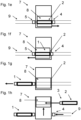
- Figure 1 shows a schematic sequence of an embodiment of a method for forming a train 1 from at least one road trailer 2 suitable for transporting goods and at least two bogies 4, 5 guided on a track 9 by means of a loading device 7 which can be moved at least transversely to the track direction.
- the process is carried out by a schematically illustrated horizontal handling system 13 (see also Figures 3a and 3b ) to form a train 1 (see also Figure 1h and Figure 8 ) of at least one road trailer 2 suitable for the transport of goods and bogies 4, 5 guided on a track 9 accessible for rail vehicles, comprising at least loading device 7 movable transversely to the track direction with at least one platform 8, a track for the train 1 (see Figure 8 ) forming tracks 9 with two essentially parallel rails and at least two bogies 4, 5 guided on the tracks 9.
- the loading device 7 has a platform 8 with a track section 10 that can be moved at least transversely to the track direction of the tracks 9 between a loading position next to the tracks 9 and a coupling position.
- the track 9 can be designed to be continuously accessible for rail vehicles through the track section 10.
- the bogies 4, 5 can be provided spaced apart from one another in the track direction such that a road trailer 2 can be arranged between the bogies 4, 5.
- the road trailer 2 is parked on the platform 8 of the loading device 7, which can be moved at least transversely to the track direction. As shown, the road trailer 2 can be parked on a platform designed to support the support legs and wheels of the Road trailer (see Figure 4 ) suitable platform 8.
- the loading device 7 can be designed to be directly accessible, whereby the road trailer 2 can drive directly onto the loading device 7.
- the road trailer 2 can be driven onto the loading device 7, for example, by a tractor 3.
- the road trailer 2 is loaded with the loading device 7, here by means of the movable platform 8, between the two bogies 4, 5 spaced apart from each other in the track direction.
- the road trailer 2 is coupled to a first bogie 4 by a relative movement between the road trailer 2 and the first bogie 4 in the track direction.
- the relative movement can be achieved by a movement of the road trailer 2 and/or the bogie 4 in the track direction, whereby a coupling mechanism can be actuated.
- the road trailer 2 is coupled to the second bogie 5 by a relative movement between the road trailer 2 together with the coupled first bogie 4 and the second bogie 5 in the track direction.
- the loading device 7, in particular its platform 8, can be movable in the track direction and the relative movement for coupling the road trailer 2 to the Bogies 4, 5 by a movement of the loading device 7 in track direction 8.
- a relative movement between the road trailer 2 and the bogies 4, 5 can in principle also occur through a driving movement of the bogies 4, 5.
- the relative movement for coupling the road trailer 2 placed between the bogies 4, 5 to the bogies 4, 5 can essentially only be a relative movement in the track direction.
- Train 1 formed from a road trailer 2 and two bogies 4, 5 can be extended by repeating the process steps with further road trailers 2 and further bogies 6.
- the train 1 is moved a little way in the direction of the track, the loading device 7 is reconfigured to park a road trailer 2 and another bogie 6 is provided on track 9.
- the road trailer 2 can be at least partially lifted to a coupling level above the track level suitable for coupling the road trailer 2 and a bogie 4, 5 guided on the track 9 by driving the road trailer 2 onto the loading device 7 which can be moved at least transversely to the track direction.
- At least partial lifting can be achieved by a height-adjustable air suspension of the axles of the wheels 11 of the road trailer 2, as shown in Figure 3 is shown.
- an at least partial lifting of a road trailer 2 to a coupling level above the track level can be carried out by at least one height-adjustable platform part 41, 42, 43, 44 of the at least one platform 8 of the loading device 7 for supporting wheels 11 and optionally support legs 12 of the road trailer 2 (see, for example, Figure 2 and Figure 3 ).
- a sequence of Figures 1a to 1h can correspond to clearing an existing move 1.
- Figure 2 1 shows an embodiment of a road trailer 2 suitable for transporting goods.
- the road trailer 2 has a chassis that is height-adjustable, for example via air springs, with wheels 11 for direct driving on a road, a kingpin 33, a foldable underrun protection 35, and a frame 28 with connecting means 24 arranged on or in the frame 28 for coupling to bogies 4, 5.
- the trailer may have measuring marks 34, which can be detected by a position detection device of the horizontal handling system 13.
- a position detection device of the horizontal handling system 13 may also be able to detect a position of the road trailer 2 without the measuring marks 34.
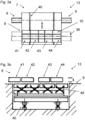
- the horizontal handling system 12 comprises in the design of the Figure 3 a loading device 7 movable at least transversely to the track direction with a platform 8, tracks 9 forming a track for the train 1 with two essentially parallel rails and bogies 4, 5 not shown here (see, however, Figure 1 ).
- the loading device 7 is arranged transversely to the track direction adjacent to the tracks 9.
- the platform 8 of the loading device 7 is movable at least transversely to the track direction between a loading position shown next to the tracks 9 and a coupling position, wherein the platform 8 of the loading device 7 has at least one track section 10 and the tracks 9 are continuously extendable for rail vehicles in the coupling position of the loading device 7, in particular in an unraised state of the platform 8.
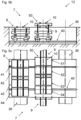
- the platform 8 of the loading device 7 has four height-adjustable platform parts 41, 42, 43, 44 for supporting wheels 11 and, if necessary, support legs 12 of a road trailer 2 (see Figure 3b ).
- the platform parts 41, 42, 43, 44 as well as a non-height-adjustable central part of the platform 8 each have unspecified track sections, so that for the platform 8 as a whole there is a track section 10 that can be used by a rail vehicle.
- the track 9 can be designed, at least in sections, as a mat track with a flush running surface 36 for road vehicles.
- the level of the running surface 36 can be flush with the upper edge of the track, at least in sections around the tracks 9.
- the height-adjustable platform parts 41, 42, 43, 44 are, as in Figure 3b (Section in a vertical plane in the track direction, between the tracks 9, viewing direction transverse to the track direction, platform 8 in coupling position, tracks 9 hidden), movable between a lower position, preferably at track level for driving onto the loading device 7, and an upper position for coupling a road trailer 2 and a bogie 4, 5 guided on the track 9.
- Figure 3b shows an overlay of a representation with platform parts 41, 42, 43, 44 in a lower position and a representation with platform parts 41, 42, 43, 44 in an upper position, which are also moved in the track direction.
- the non-height-adjustable middle section of platform 8 can also be moved in the track direction (not shown).
- platform 8 in the unraised state, to extend track 9 with track section 10 in a way that allows continuous travel, although it may be that in this state no movement of platform 8 or platform parts 41, 42, 43, 44 in the track direction is possible.
- the platform in particular the platform parts 41, 42, 43, 44, partly above the tracks 9, whereby a movement of the platform 8 in the track direction can be enabled in the coupling position related to the transverse offset.
- the platform parts 41, 42, 43, 44 can be lifted and moved by a lifting system 45 not described in detail here.
- the platform 8 of the loading device 7 can be moved on a rail system 40 transversely to the track direction.
- FIG. 4a to 4c is essentially the Figures 1c to 1f
- the design of the horizontal handling system 13 essentially corresponds to that of the Figure 3
- the loading device 7 thus has a platform 8 that can be moved at least transversely to the track direction.
- a side view and a top view of the horizontal handling system 13 are shown.
- the platform 8 of the loading device 7 is in an unraised loading position next to the tracks 9.
- a road trailer 12 has been parked, for example, by driving a tractor (not shown) directly onto the platform 8.
- the wheels 11 of the road trailer are supported on the platform parts 43, 44 of the platform 8.
- the platform 8 can be used in both directions of travel.
- An at least partial lifting of the road trailer 2 to a coupling level above the track level can be carried out by the height-adjustable platform parts 41, 42, 43, 44, as shown in Figure 4c is shown.
- the platform parts 41, 42, 43, 44 can be moved from a lower position, which is preferably located at track level for driving onto the loading device 7, into an upper position, which is suitable for coupling the road trailer 2 and a bogie 4, 5 guided on the track 9.
- At least partial lifting can be carried out before, during and/or after a Figure 3b
- the method shown for moving the platform 8 of the loading device 3 transversely to the track direction into the coupling position can be carried out.
- the loading device can have several platforms which can be arranged adjacent to one another in the track direction and/or transversely to the track direction.
- the loading facility has several platforms, these can be essentially identical.
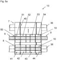
- the horizontal handling system 13 in the design of the Figures 5a and 5b Compared to the execution of the Figure 3 a loading device 7 with a first platform 8 on a rail system 40 with movable platform parts 41, 42, 43, 44 and additionally a second platform 50 arranged transversely to the track direction next to it with movable platform parts 51, 52, 53, 54.
- FIGS. 5b and 5c show a sectional view transverse to the track direction and a top view, wherein the platform 8 of the loading device 7 is in an unraised state and the further platform 50 of the loading device 7 is in a raised and moved in the track direction state (compare also Figure 3b ).
- the platforms 7 and 50 can in principle be moved independently of each other or together.
- the movable platform parts 41, 42, 43, 44 and the movable platform parts 51, 52, 53, 54 can be moved independently of each other (see, for example, Figure 5b ).
- the additional platform 50 arranged next to it can be moved together transversely to the track direction between an alternating loading position next to the tracks and a coupling position.
- the provision of the bogies 4, 5 and the parking of the road trailer 2 can be carried out for a design of the loading device 7 as in Figure 5 shown, are basically carried out independently of each other, which is why corresponding process steps for such an execution can in principle also take place simultaneously.
- a road trailer 2 already parked on platform 50 can be coupled to bogies 4, 5 not shown here (see specifically Figure 5c ).
- the road trailer 2 parked on the platform 7 can be coupled to bogies 4, 5, while the further platform 50 can be loaded with another road trailer 2 via the running surface 36.
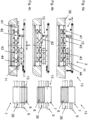
- FIGs 6a and 6b are views of a design of a bogie 4, which has a bogie frame 16 with wheelset 17 for driving on the tracks 9 and a joint socket 15 for a cradle 18 (see Figure 7a ) for supporting a road trailer 2.
- Figure 7a shows a sectional view with a cutting plane in the direction of the track.
- Figure 7b shows a top view of a cradle 18.
- the cradle 18 is mounted on the bogie frame 16 via a first ball joint 19 in a joint socket 15. This allows movement between supports 20, 21 of the cradle 18 and the bogie frame 16.
- a stretching element 30, for example of a spring-like design, and at least four length-adjustable support elements 14 are arranged between the supports 20, 21.
- the cradle 18 is formed in two parts with two supports 20, 21, wherein the supports 20, 21 are connected to each other via a second ball joint 22. This allows a Movement between the supports 20, 21 of the cradle 18 and subsequently movement between road trailers 2 supported on the supports 20, 21 are enabled.
- Support elements 14 can be arranged between beams 20, 21 of the cradle 18 and the bogie frame 16.
- the cradle 18 has receptacles 23 for connecting means 24, in particular for pins, arranged on a frame 28 of a road trailer 2.
- the receptacles 23 can, as shown by way of example, be designed in the form of openings in the cradle 18.
- FIGs 7c and 7d an embodiment of a locking device 25 of the bogies 4, 5 for locking the connecting means 24 is shown, wherein in Figure 7c the locking device 25 is shown in an unlocked position and in Figure 7d the locking device 25 in a locked position.
- the locking device 25 can be arranged on supports 20, 21 of the cradle 18.
- the locking device 25 arranged on the supports 20, 21 of the cradle 18 has two locking elements 26 which can be moved transversely to the track direction, in particular horizontally and transversely to the track direction.
- the locking elements 26 are designed in the form of a locking bolt.
- the locking elements 26 can be moved into a locking position by a pneumatically or electromechanically actuated spindle drive 31.
- the locking element 26 has wedge-shaped flattened contact surfaces 27 in the longitudinal direction for engagement with correspondingly flattened contact surfaces 29 of the connecting means 24, the interaction of which during locking can produce a surface pressure favorable for force absorption.
- the locking elements 26 can be mounted at least partially rotatably in the circumferential direction, so that an automatic alignment with one another can result during locking.
- the locking device 25 can be mounted floatingly on the supports 20, 21 of the cradle 18 via a hollow spring 32 in the longitudinal direction of the spindle drive 31.
- Figure 8 shows an embodiment of a train 1 formed (or to be cleared) by means of a horizontal transfer system 13 as described above with a rail-bound traction vehicle 38, several bogies 4 and several road trailers 2 coupled to the bogies.
- the bogies of train 1 can be designed as central bogies arranged between the road trailers 2 and end bogies arranged at the end or beginning of the train, the differences being essentially due to the receptacles for connecting means and buffers for shocks in the track direction.
Landscapes
- Engineering & Computer Science (AREA)
- Mechanical Engineering (AREA)
- Transportation (AREA)
- Handcart (AREA)
- Loading Or Unloading Of Vehicles (AREA)
Claims (15)
- Procédé de formation d'un train (1) composé d'au moins une remorque routière (2) adaptée au transport de marchandises et d'au moins deux bogies (4, 5) guidés sur une voie (9) sur laquelle peuvent circuler des véhicules ferroviaires au moyen d'un dispositif de chargement (7) déplaçable au moins transversalement au sens de la voie avec au moins une plateforme (8), caractérisé par les étapes de procédé suivantes :- la mise à disposition d'au moins deux bogies (4, 5) espacés l'un de l'autre dans le sens de la voie sur la voie (9),- le stationnement de la remorque routière (2) sur la plateforme (8) du dispositif de chargement (7) déplaçable au moins transversalement au sens de la voie, de préférence en remontant la remorque routière (2) sur la plateforme (8) du dispositif de chargement (7),- le chargement de la remorque routière (2) au moyen du dispositif de chargement (7) entre deux bogies (4, 5) espacés l'un de l'autre dans le sens de la voie,- l'accouplement de la remorque routière (2) à un premier bogie (3) des deux bogies (4, 5) par un mouvement relatif entre la remorque routière (2) et le premier bogie (4) dans le sens de la voie,- l'accouplement de la remorque routière (2) au second bogie (5) des deux bogies (4, 5) par un mouvement relatif entre la remorque routière (2) conjointement avec le premier bogie (4) accouplé et le second bogie (5) dans le sens de la voie.
- Procédé selon la revendication 1, dans lequel le dispositif de chargement (7) est déplaçable dans le sens de la voie et le mouvement relatif pour l'accouplement de la remorque routière (2) aux bogies (4, 5) s'effectue par un mouvement de l'au moins une plateforme (8) du dispositif de chargement (7) dans le sens de la voie,
dans lequel il est préféré que lors du déplacement de l'au moins une plateforme (8) du dispositif de chargement (7) dans le sens de la voie, au moins un déplacement de la remorque routière (2) stationnée sur le dispositif de chargement (7) s'effectue. - Procédé selon l'une quelconque des revendications précédentes, dans lequel lors du stationnement de la remorque routière (2) sur le dispositif de chargement (7), un appui de jambes d'appui (12) de la remorque routière (2) s'effectue par un réglage en hauteur d'au moins une partie de plateforme (41, 42, 43, 44) réglable en hauteur de la plateforme (8) du dispositif de chargement (7) pour soutenir des roues (11) et/ou des jambes d'appui (12) d'une remorque routière (2).
- Procédé selon l'une quelconque des revendications précédentes, dans lequel un soulèvement au moins partiel de la remorque routière (2) sur un niveau d'accouplement adapté à l'accouplement de la remorque routière (2) et à un bogie (4, 5) guidé sur la voie (9) au-dessus du niveau de la voie s'effectue par une remontée de la remorque routière (2) sur le dispositif de chargement (7) déplaçable au moins transversement au sens de la voie et/ou une suspension pneumatique réglable en hauteur des essieux des roues (11) de la remorque routière (2),
et/ou dans lequel un soulèvement au moins partiel d'une remorque routière (2) à un niveau d'accouplement au-dessus du niveau de la voie s'effectue par au moins une partie de plateforme (41, 42, 43, 44) réglable en hauteur de l'au moins une plateforme (8) du dispositif de chargement (7) pour soutenir des roues (11) et, le cas échéant, des jambes d'appui (12) de la remorque routière (2), d'une position basse, de préférence au niveau de la voie de circulation du dispositif de chargement (7), et d'une position haute, qui est adaptée à l'accouplement de la remorque routière (2) et d'un bogie (4, 5) guidé sur la voie (9). - Procédé selon l'une quelconque des revendications précédentes, dans lequel lors du chargement de la remorque routière (2) au moyen du dispositif de chargement (7) entre deux bogies (4, 5) espacés l'un de l'autre dans le sens de la voie, la plateforme (8) du dispositif de chargement (7) est déplacée au moins transversalement au sens de la voie entre une position de chargement à côté des voies (9) et une position d'accouplement et les voies (9) peuvent être allongées en continu dans la position d'accouplement du dispositif de chargement (7) par au moins une section de voie (10) de la plateforme (8), en particulier dans un état non soulevé de la plateforme (8), pour des véhicules ferroviaires.
- Procédé selon l'une quelconque des revendications précédentes, dans lequel lors d'un mouvement de la plateforme (8) du dispositif de chargement (7) transversalement au sens de la voie, une autre plateforme (50) disposée transversalement au sens de la voie à côté de la plateforme (8) est déplacée ensemble transversalement au sens de la voie entre une position de chargement respectivement alternée à côté des voies (9) et une position d'accouplement.
- Dispositif de transbordement horizontal (13) pour la formation d'un train (1) composé d'au moins une remorque routière (2) adaptée au transport de marchandises et d'au moins deux bogies (4, 5) guidés sur une voie (9) sur laquelle peuvent circuler des véhicules ferroviaires pour réaliser un procédé selon l'une quelconque des revendications précédentes, comprenant :- un dispositif de chargement (7) déplaçable au moins transversalement au sens de la voie avec au moins une plateforme (8)- des voies (9) formant une voie de circulation pour le train avec deux rails posés sensiblement parallèlement- au moins deux bogies (4, 5) guidés sur les voies (9)caractérisé en ce qu'au moins une partie du dispositif de chargement (7) peut être déplacée dans le sens de la voie par un mouvement de l'au moins une plateforme (8) et qu'un accouplement de la remorque routière (2) aux bogies (4, 5) peut être réalisé par le mouvement.
- Dispositif de transbordement horizontal selon la revendication 7, dans lequel le dispositif de chargement (7) est disposé transversalement au sens de la voie de manière adjacente aux voies (9).
- Dispositif de transbordement horizontal selon l'une quelconque des revendications 7 ou 8, dans lequel la plateforme (8) du dispositif de chargement (7) peut être déplacée au moins transversalement au sens de la voie entre une position de chargement à côté des voies (9) et une position d'accouplement, dans lequel la plateforme (8) du dispositif de chargement (7) présente au moins une section de voie (10) et les voies (9) dans la position d'accouplement du dispositif de chargement (7), en particulier dans un état non soulevé de la plateforme (8), peuvent être allongées en continu pour des véhicules ferroviaires,
et/ou dans lequel la plateforme (8) du dispositif de chargement (7) présente au moins une partie de plateforme (41, 42, 43, 44) réglable en hauteur pour soutenir des roues (11) et/ou des jambes d'appui (12) d'une remorque routière (2). - Dispositif de transbordement horizontal selon l'une quelconque des revendications 7 à 9, dans lequel la plateforme (8) du dispositif de chargement (7) présente au moins une partie de plateforme (41, 42, 43, 44) réglable en hauteur pour soutenir des roues (11) et, le cas échéant, des jambes d'appui (12) d'une remorque routière (2), dans lequel l'au moins une partie de plateforme (41, 42, 43, 44) réglable en hauteur est mobile entre une position basse, de préférence au niveau de la voie pour la circulation du dispositif de chargement (7), et une position haute pour accoupler une remorque routière (2) et un bogie (4, 5) guidé sur la voie (9).
- Dispositif de transbordement horizontal selon l'une quelconque des revendications 7 à 10, dans lequel le dispositif de chargement (7) présente au moins une plateforme (8) et une autre plateforme (50) disposée transversalement au sens de la voie à côté de la plateforme (8), dans lequel la plateforme (8) et l'autre plateforme (50) peuvent être déplacées ensemble transversalement au sens de la voie entre une position de chargement respectivement alternée à côté des voies (9) et une position d'accouplement.
- Dispositif de transbordement horizontal selon l'une quelconque des revendications 7 à 11, dans lequel les bogies (4, 5) présentent un châssis de bogie (16) avec un train de roues (17) pour circuler sur les voies (9) et un berceau (18) pour soutenir une remorque routière (2).
- Dispositif de transbordement horizontal selon la revendication précédente, dans lequel le berceau (18) est logé par le biais d'une première rotule (19) sur le châssis de bogie (16), et/ou le berceau (18) est conçu en deux parties avec deux supports (20, 21) et les supports (20, 21) sont reliés entre eux par le biais d'une seconde rotule (22), et/ou
- Dispositif de transbordement horizontal selon la revendication 12 ou la revendication 13, dans lequel le berceau (18) présente des logements (23) pour des moyens de liaison (24) disposés sur une remorque routière (2), en particulier pour des tenons, dans lequel le berceau (18) est de préférence conçu en deux parties avec des supports (20, 21) reliés par le biais d'une seconde rotule (22) et les supports (20, 21) présentent chacun au moins un logement (23), dans lequel il est préféré que
le berceau (18) présente un dispositif de verrouillage (25) pour le verrouillage des moyens de liaison (24), dans lequel le dispositif de verrouillage (25) présente de préférence un élément de verrouillage (26) mobile transversalement au sens de la voie. - Agencement composé d'un dispositif de transbordement horizontal (13) pour la formation d'un train (1) selon l'une quelconque des revendications 7 à 14 et au moins une remorque routière (2) adaptée au transport de marchandises, dans lequel la remorque routière (2) présente un châssis avec des roues (11) pour circuler directement sur une route et un cadre (28) avec des moyens de liaison (24) disposés sur le cadre (28).
Applications Claiming Priority (2)
| Application Number | Priority Date | Filing Date | Title |
|---|---|---|---|
| ATA50355/2021A AT525096B1 (de) | 2021-05-07 | 2021-05-07 | Verfahren zum Bilden eines Zuges |
| PCT/EP2022/062281 WO2022234084A1 (fr) | 2021-05-07 | 2022-05-06 | Procédé de formation d'un train |
Publications (3)
| Publication Number | Publication Date |
|---|---|
| EP4334183A1 EP4334183A1 (fr) | 2024-03-13 |
| EP4334183C0 EP4334183C0 (fr) | 2025-06-18 |
| EP4334183B1 true EP4334183B1 (fr) | 2025-06-18 |
Family
ID=81975217
Family Applications (1)
| Application Number | Title | Priority Date | Filing Date |
|---|---|---|---|
| EP22728377.7A Active EP4334183B1 (fr) | 2021-05-07 | 2022-05-06 | Procédé de formation d'un train |
Country Status (3)
| Country | Link |
|---|---|
| EP (1) | EP4334183B1 (fr) |
| AT (1) | AT525096B1 (fr) |
| WO (1) | WO2022234084A1 (fr) |
Family Cites Families (6)
| Publication number | Priority date | Publication date | Assignee | Title |
|---|---|---|---|---|
| US4385857A (en) * | 1979-04-24 | 1983-05-31 | Willetts Elwood H | Intermodal transport system |
| DE3344513A1 (de) * | 1983-12-09 | 1985-06-20 | Ackermann-Fruehauf Corporation & Co Ohg, 5600 Wuppertal | Kombiniertes strassen- und bahn-transportsystem |
| DE19801880A1 (de) * | 1998-01-20 | 1999-07-22 | Volker H Rosenkranz | Anlage zum Umsetzen der Frachtcontainer vom LKW auf die Bahn und umgekehrt |
| EP2509845B1 (fr) * | 2009-12-07 | 2017-07-19 | Railrunner N.A., Inc. | Véhicule sur rails intermodal amélioré permettant de former un train |
| DE102010019002A1 (de) * | 2010-05-03 | 2011-11-03 | RLI - Rail Logistik Innovation GbR mbH (vertretungsberechtigte Gesellschafter: Hans-Wilhelm Peters, 79837 St. Blasien; Bruno Lichtnow, 26759 Hinte) | Verfahren und Vorrichtung zum Verladen vom Güterverkehr auf die Schiene |
| CN110758032B (zh) * | 2019-12-04 | 2023-04-11 | 中车眉山车辆有限公司 | 一种公铁两用运输车组及其编组方法 |
-
2021
- 2021-05-07 AT ATA50355/2021A patent/AT525096B1/de active
-
2022
- 2022-05-06 WO PCT/EP2022/062281 patent/WO2022234084A1/fr not_active Ceased
- 2022-05-06 EP EP22728377.7A patent/EP4334183B1/fr active Active
Also Published As
| Publication number | Publication date |
|---|---|
| AT525096A4 (de) | 2022-12-15 |
| EP4334183C0 (fr) | 2025-06-18 |
| AT525096B1 (de) | 2022-12-15 |
| WO2022234084A1 (fr) | 2022-11-10 |
| EP4334183A1 (fr) | 2024-03-13 |
Similar Documents
| Publication | Publication Date | Title |
|---|---|---|
| DE102004040245A1 (de) | Güterumschlagverfahren und Transportsystem | |
| EP1519868B1 (fr) | Procede de chargement et de dechargement de wagons de chemin de fer et dispositif, chassis de wagon et superstructure de wagon pour mettre ledit procede en oeuvre | |
| EP2384947A1 (fr) | Procédé et dispositif de chargement du transport de marchandises sur le rail | |
| EP2792515A2 (fr) | Système de véhicule destiné à transporter des marchandises sur rails et sur routes, kit de rééquipement de wagon d'un système de véhicule destiné à transporter des marchandises sur rails et sur routes et procédé de rééquipement | |
| EP1582496B1 (fr) | Procédé pour manipuler une semi-remorque et moyens de saisie pour la mise en oeuvre de ce procédé | |
| EP4334183B1 (fr) | Procédé de formation d'un train | |
| EP4334184B1 (fr) | Bogie pour former un train | |
| DE4414528C2 (de) | Anlage zum Be- und Entladen von Eisenbahnwaggons | |
| EP1355815A1 (fr) | Procede et vehicule a plate-forme surbaissee pour le transport de vehicules routiers sur rails | |
| DE102013204279A1 (de) | Ladungsträger für kombinierten Warenverkehr | |
| EP0742130A1 (fr) | Unité ferroviaire de transport pour le transport mixte de conteneurs et/ou conteneurs interchangeables et semi-remorques | |
| DE69511673T2 (de) | Auf Eisenbahnwagen transportierbare Rampen zum Verladen von Standard-Sattelaufliegern auf, aus besonderen Einheiten zusammengestellte, Züge | |
| DE69803486T2 (de) | Auf gleisen vefahrbares frachtfahrzeug | |
| DE3787146T2 (de) | Sattelanhänger für Schiene und Strasse. | |
| EP0538648B1 (fr) | Wagon porteur pour le transport combiné rail-route | |
| DE10230110A1 (de) | Verfahren zum Be- und Entladen von Schienenwaggons sowie Vorrichtung, Waggongestell und Waggonaufsatz zum Durchführen des Verfahrens | |
| DE4134903A1 (de) | Tragwagen fuer den kombinierten ladungsverkehr | |
| DE19515110A1 (de) | Schienenlaufwerk für einen Schienen-Transportverbund | |
| EP4137360B1 (fr) | Remorque porte-voiture | |
| DE102021104173B4 (de) | Eisenbahnwagen mit einer Schwenkbrücke | |
| DE10101891B4 (de) | Be- und Entladesystem von Fahrzeug-Einheiten | |
| DE19515109A1 (de) | Ladungsträger, insbesondere Wechselaufbau oder Container von Lastfahrzeugen | |
| DE19520549A1 (de) | Straßen-Schienen-Transportsystem | |
| DE102014115436A1 (de) | Eisenbahnwagen | |
| EP0362187A1 (fr) | Système de transport par chemin de fer |
Legal Events
| Date | Code | Title | Description |
|---|---|---|---|
| STAA | Information on the status of an ep patent application or granted ep patent |
Free format text: STATUS: UNKNOWN |
|
| STAA | Information on the status of an ep patent application or granted ep patent |
Free format text: STATUS: THE INTERNATIONAL PUBLICATION HAS BEEN MADE |
|
| PUAI | Public reference made under article 153(3) epc to a published international application that has entered the european phase |
Free format text: ORIGINAL CODE: 0009012 |
|
| STAA | Information on the status of an ep patent application or granted ep patent |
Free format text: STATUS: REQUEST FOR EXAMINATION WAS MADE |
|
| 17P | Request for examination filed |
Effective date: 20231201 |
|
| AK | Designated contracting states |
Kind code of ref document: A1 Designated state(s): AL AT BE BG CH CY CZ DE DK EE ES FI FR GB GR HR HU IE IS IT LI LT LU LV MC MK MT NL NO PL PT RO RS SE SI SK SM TR |
|
| DAV | Request for validation of the european patent (deleted) | ||
| DAX | Request for extension of the european patent (deleted) | ||
| GRAP | Despatch of communication of intention to grant a patent |
Free format text: ORIGINAL CODE: EPIDOSNIGR1 |
|
| STAA | Information on the status of an ep patent application or granted ep patent |
Free format text: STATUS: GRANT OF PATENT IS INTENDED |
|
| INTG | Intention to grant announced |
Effective date: 20241211 |
|
| GRAS | Grant fee paid |
Free format text: ORIGINAL CODE: EPIDOSNIGR3 |
|
| GRAA | (expected) grant |
Free format text: ORIGINAL CODE: 0009210 |
|
| STAA | Information on the status of an ep patent application or granted ep patent |
Free format text: STATUS: THE PATENT HAS BEEN GRANTED |
|
| AK | Designated contracting states |
Kind code of ref document: B1 Designated state(s): AL AT BE BG CH CY CZ DE DK EE ES FI FR GB GR HR HU IE IS IT LI LT LU LV MC MK MT NL NO PL PT RO RS SE SI SK SM TR |
|
| REG | Reference to a national code |
Ref country code: GB Ref legal event code: FG4D Free format text: NOT ENGLISH |
|
| REG | Reference to a national code |
Ref country code: CH Ref legal event code: EP |
|
| REG | Reference to a national code |
Ref country code: DE Ref legal event code: R096 Ref document number: 502022004338 Country of ref document: DE |
|
| REG | Reference to a national code |
Ref country code: CH Ref legal event code: EP |
|
| REG | Reference to a national code |
Ref country code: IE Ref legal event code: FG4D Free format text: LANGUAGE OF EP DOCUMENT: GERMAN |
|
| U01 | Request for unitary effect filed |
Effective date: 20250618 |
|
| U07 | Unitary effect registered |
Designated state(s): AT BE BG DE DK EE FI FR IT LT LU LV MT NL PT RO SE SI Effective date: 20250625 |
|
| PG25 | Lapsed in a contracting state [announced via postgrant information from national office to epo] |
Ref country code: NO Free format text: LAPSE BECAUSE OF FAILURE TO SUBMIT A TRANSLATION OF THE DESCRIPTION OR TO PAY THE FEE WITHIN THE PRESCRIBED TIME-LIMIT Effective date: 20250918 Ref country code: GR Free format text: LAPSE BECAUSE OF FAILURE TO SUBMIT A TRANSLATION OF THE DESCRIPTION OR TO PAY THE FEE WITHIN THE PRESCRIBED TIME-LIMIT Effective date: 20250919 |
|
| PG25 | Lapsed in a contracting state [announced via postgrant information from national office to epo] |
Ref country code: HR Free format text: LAPSE BECAUSE OF FAILURE TO SUBMIT A TRANSLATION OF THE DESCRIPTION OR TO PAY THE FEE WITHIN THE PRESCRIBED TIME-LIMIT Effective date: 20250618 |
|
| PG25 | Lapsed in a contracting state [announced via postgrant information from national office to epo] |
Ref country code: RS Free format text: LAPSE BECAUSE OF FAILURE TO SUBMIT A TRANSLATION OF THE DESCRIPTION OR TO PAY THE FEE WITHIN THE PRESCRIBED TIME-LIMIT Effective date: 20250918 |
|
| PG25 | Lapsed in a contracting state [announced via postgrant information from national office to epo] |
Ref country code: IS Free format text: LAPSE BECAUSE OF FAILURE TO SUBMIT A TRANSLATION OF THE DESCRIPTION OR TO PAY THE FEE WITHIN THE PRESCRIBED TIME-LIMIT Effective date: 20251018 |
|
| PG25 | Lapsed in a contracting state [announced via postgrant information from national office to epo] |
Ref country code: SM Free format text: LAPSE BECAUSE OF FAILURE TO SUBMIT A TRANSLATION OF THE DESCRIPTION OR TO PAY THE FEE WITHIN THE PRESCRIBED TIME-LIMIT Effective date: 20250618 |
|
| PG25 | Lapsed in a contracting state [announced via postgrant information from national office to epo] |
Ref country code: CZ Free format text: LAPSE BECAUSE OF FAILURE TO SUBMIT A TRANSLATION OF THE DESCRIPTION OR TO PAY THE FEE WITHIN THE PRESCRIBED TIME-LIMIT Effective date: 20250618 |
|
| PG25 | Lapsed in a contracting state [announced via postgrant information from national office to epo] |
Ref country code: PL Free format text: LAPSE BECAUSE OF FAILURE TO SUBMIT A TRANSLATION OF THE DESCRIPTION OR TO PAY THE FEE WITHIN THE PRESCRIBED TIME-LIMIT Effective date: 20250618 |
|
| PG25 | Lapsed in a contracting state [announced via postgrant information from national office to epo] |
Ref country code: SK Free format text: LAPSE BECAUSE OF FAILURE TO SUBMIT A TRANSLATION OF THE DESCRIPTION OR TO PAY THE FEE WITHIN THE PRESCRIBED TIME-LIMIT Effective date: 20250618 |
|
| PG25 | Lapsed in a contracting state [announced via postgrant information from national office to epo] |
Ref country code: ES Free format text: LAPSE BECAUSE OF FAILURE TO SUBMIT A TRANSLATION OF THE DESCRIPTION OR TO PAY THE FEE WITHIN THE PRESCRIBED TIME-LIMIT Effective date: 20250618 |
|
| PLBE | No opposition filed within time limit |
Free format text: ORIGINAL CODE: 0009261 |
|
| STAA | Information on the status of an ep patent application or granted ep patent |
Free format text: STATUS: NO OPPOSITION FILED WITHIN TIME LIMIT |
|
| REG | Reference to a national code |
Ref country code: CH Ref legal event code: L10 Free format text: ST27 STATUS EVENT CODE: U-0-0-L10-L00 (AS PROVIDED BY THE NATIONAL OFFICE) Effective date: 20260430 |