EP4137422A1 - Automatisiertes system zum speichern und wiederauffinden von chips - Google Patents
Automatisiertes system zum speichern und wiederauffinden von chips Download PDFInfo
- Publication number
- EP4137422A1 EP4137422A1 EP20931343.6A EP20931343A EP4137422A1 EP 4137422 A1 EP4137422 A1 EP 4137422A1 EP 20931343 A EP20931343 A EP 20931343A EP 4137422 A1 EP4137422 A1 EP 4137422A1
- Authority
- EP
- European Patent Office
- Prior art keywords
- platform
- carriage
- shelves
- movement
- frame
- Prior art date
- Legal status (The legal status is an assumption and is not a legal conclusion. Google has not performed a legal analysis and makes no representation as to the accuracy of the status listed.)
- Granted
Links
Images









Classifications
-
- B—PERFORMING OPERATIONS; TRANSPORTING
- B65—CONVEYING; PACKING; STORING; HANDLING THIN OR FILAMENTARY MATERIAL
- B65G—TRANSPORT OR STORAGE DEVICES, e.g. CONVEYORS FOR LOADING OR TIPPING, SHOP CONVEYOR SYSTEMS OR PNEUMATIC TUBE CONVEYORS
- B65G1/00—Storing articles, individually or in orderly arrangement, in warehouses or magazines
- B65G1/02—Storage devices
- B65G1/04—Storage devices mechanical
- B65G1/0407—Storage devices mechanical using stacker cranes
-
- B—PERFORMING OPERATIONS; TRANSPORTING
- B65—CONVEYING; PACKING; STORING; HANDLING THIN OR FILAMENTARY MATERIAL
- B65G—TRANSPORT OR STORAGE DEVICES, e.g. CONVEYORS FOR LOADING OR TIPPING, SHOP CONVEYOR SYSTEMS OR PNEUMATIC TUBE CONVEYORS
- B65G1/00—Storing articles, individually or in orderly arrangement, in warehouses or magazines
- B65G1/02—Storage devices
- B65G1/04—Storage devices mechanical
- B65G1/0407—Storage devices mechanical using stacker cranes
- B65G1/0421—Storage devices mechanical using stacker cranes with control for stacker crane operations
Definitions
- Spanish invention patent ES2005404 already discloses a robotic carriage intended for removing or depositing dies from a corresponding warehouse in a fully automated manner.
- Said carriage moves on rails, while the lifting frame is lifted to the desired position by means of a hydraulic cylinder.
- a cylinder causes the frame to move transversely towards the inside of the warehouse, bringing the roller platform of the frame closer to the die loading/unloading area.
- Spanish utility model ES1006554U shows a modular warehouse for the storage of dies, which makes it easy for an automated robotic carriage to perform the maneuvers of introducing and removing dies.
- the warehouse comprises a guide intended for collaborating with an existing groove in the die, and rollers which facilitate the movement of the die but at the same time constitute respective guides for the entry of the platform of the robotic carriage.
- United States patent US9415933B2 discloses a die warehouse in which the removal or deposition of dies is carried out in an automatic manner. In this case, the carriage moves on rails and its platform is lifted by the chains of a crane. Likewise, this platform also moves laterally to collect or deposit the desired die.
- the platform in order to deposit a die, the platform is first fixed to the shelf of the warehouse and a table is lifted moving the die. Next, the platform moves laterally, bringing the die to its storage area, and then the table lowers, leaving the die in place on a support of a tray in the warehouse.
- European Patent EP2566789B1 discloses an automated warehouse for any type of articles, in which there is also a carriage which carries and collects articles from shelves, with both the shelves and the platform of the carriage having mutually reciprocating guides that allow a correct transverse movement without play.
- the carriage is capable of moving according to an "X" axis between the shelves following rails and in a duly guided manner.
- the carriage in turn preferably incorporates four columns arranged according to each of its corners and a platform.
- the platform is mechanically connected to the columns to be moved vertically according to the "Y" axis.
- the columns incorporate first linear movement means.
- the columns are synchronized with one another to carry out the vertical movement of the platform, such that it remains perfectly horizontal at all times.
- the columns have guide elements in the upper part thereof, which are complementary to the channel elements located in the shelves which correspond to said guide elements.
- the carriage moves according to the X axis, being guided in the lower portion thereof by means of rolling elements and their respective channelings, as well as being guided in the upper portion thereof by means of the aforementioned guide elements and the channel elements, providing stability to the assembly formed by the carriage and the platform.
- this solution enables a load placed on the platform arranged in the carriage to move simultaneously according to the "X” and “Y” axes through movement of the carriage in the "X” axis and the movement of the platform in the "Y” axis at the same time.
- the platform of the carriage will move in height as the carriage moves towards the structure consisting of shelves, such that when the carriage reaches the corresponding point of the structure consisting of shelves, the platform is already at the level of the place where the corresponding die is to be removed or deposited.
- the movement of the platform in height will be verified, so that the platform is at the corresponding height to remove or deposit the corresponding die upon reaching said supply area.
- the platform incorporates support tables to contact and support the load to be transported. These tables comprise two parts, one upper part and one lower part. Likewise, these tables comprise linear movement means to be moved according to a "Z" axis, which will be referred to as the depth axis, both in a positive direction through the front part or side of the platform, and in a negative direction through a rear part or opposite side of the platform. These linear movement means allow the individual selection of the tables to be moved in the "Z" axis.
- the linear movement means of the tables move the two parts of each of the selected tables, depending on the dimensions and/or weight of the load.
- the tables comprise lifting means to move the upper part vertically with respect to the lower part according to the "Y" axis.
- the tables and more specifically the lower part of the tables, are provided with guiding means and both the frame of the platform and the shelves incorporate channeling means for said guiding means, such that, when the tables move in the "Z" axis, they are guided by complementary fitting of the guiding means in the channeling means.
- the lifting means of the tables allow the load to be lifted with respect to the support provided by the shelves, such that the upper part of the tables and the load itself are prevented from contacting or brushing against the shelves during the placement and removal of the load.
- the entire die loading and unloading process is fully automatic and does not require the participation of operators.
- the system object of the present invention is made up of the corresponding structure consisting of shelves (2), such that there is defined between every two rows of shelves (2) a passageway for a transport carriage to move on rails.
- the transport carriage is made up of two frames, a lower frame identified with reference number (1) and another upper frame identified with reference number (13) which is part of an upper platform (7).
- the lower frame (1) incorporates four motors (11) that move the respective wheels (12).
- Each wheel (12) is paired with a freely rotating wheel (20).
- the lower frame (1) and accordingly the transport carriage, is capable of moving longitudinally according to the "X" axis, between the shelves (2).
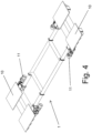
- This movement is duly guided by means of rolling means (4) of the lower frame (1) running and moving along inverted U-shaped rails (5) fixed to the shelves (2), as shown in Figure 1 .
- the lower frame (1) has in its upper part preferably four bases (10) arranged according to each of its corners. As shown in Figure 2 , columns (6) which are supported on and fixed to the bases (10) are assembled in the lower frame (1).
- FIG 3 shows a non-limiting practical embodiment of such columns (6), according to which each column (6) incorporates a seat (6.1) capable of moving vertically as a result of the action of first linear movement means formed by the motors (6.2) which are arranged at the upper end of the column (6). These motors (6.2) move the seats (6.1) in the "Y" axis through a spindle-nut mechanism.
- a platform (7) which is part of the upper frame (13) and which can therefore move vertically, according to the "Y" axis, is assembled mechanically connected to the columns (6), by means of the support and fastening thereof to the seats (6.1).
- the motors (6.2) of the columns (6) are synchronized with one another to carry out the vertical movement of the platform (7), such that it remains perfectly horizontal at all times.
- the columns (6) have, at the upper part thereof, guide elements formed by rolling means (8) that move along rails (9) fixed to the structure consisting of shelves (2).
- the carriage moves according to the "X" axis being guided in the lower portion thereof by means of the movement of the rolling means (4) on the rails (5) and additionally being guided in the upper portion thereof by means of the movement of the rolling means (8) on the rails (9), providing stability to the carriage as a whole.
- This embodiment enables the simultaneous movement according to axes "X" and "Y” of a load or die which is arranged in the transport carriage on the support tables (14) of the platform (7). This movement is achieved by the movement of the lower frame (1), and accordingly of the carriage, in the "X” axis, and by the movement of the platform (7) in the "Y” axis at the same time.
- the platform (7) When the carriage reaches the corresponding point of the structure consisting of shelves (2), the platform (7) is already at the level of the place in which the corresponding die is to be removed or deposited. In the same way, when the carriage moves towards the supply area, the movement of the platform (7) in height will be verified, so that the platform (7) is at the corresponding height to remove or deposit the corresponding die upon reaching said supply area.
- the option of the carriage moving according to the "X" axis up to the point where it should deposit or pick up a die and of the platform (7) moving according to the "Y" axis upon reaching this point obviously falls within the scope of the invention.
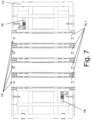
- the platform (7) is made up of two different parts, one being the frame (13), see Figures 6 and 7 , and the other being the set of support tables identified with reference number (14), for contacting and supporting the load to be transported.
- the frame (13) has vertical profiles (13.1) for the supporting the die or load to be handled thereon.
- Each table (14) is made up of two parts identified with reference numbers (14.1 and 14.2) in Figure 9 .
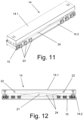
- lifting means (24) for vertically moving the upper part (14.1) with respect to the lower part (14.2) according to the "Y" axis, as shown in Figures 9 and 11 , of which Figure 9 shows the upper part (14.1) lowered and Figure 11 shows the upper part in the lifting phase.
- the lifting means (24) are formed by scissors with a central hinge (21) and end hinges (22), as shown in Figure 12 .
- Each of these support tables (14) also comprises linear movement means to be moved according to a "Z" axis, which will be referred to as the depth axis, the movement can occur both in a positive direction, through the front part of the frame (13) or through one side of the frame, and in a negative direction, when moving in the direction opposite to the previous one.
- the aforementioned linear movement means of the tables (14) are made up, for each table (14), of a rack (15) fixed to the lower part (14.2).
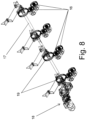
- a gear of a gear train (16) meshes with this rack (15), one of which is coupled to a gear (19) assembled on a shaft (17) actuated by a motor (18), see Figures 7 , 8 , and 13 .
- the tables (14), and more specifically the lower part (14.2) thereof, have guiding means (23), in correspondence with channeling means, both of the frame (13) and of the shelves (2), such that the tables (14) are guided by complementary fitting of the guiding means (23) in the channeling means during movements in the "Z" axis.
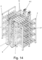
- Figure 14 shows the carriage moving forward between two rows of shelves (2) with the platform (7) lifted to the upper part of the shelf (2). It can also be seen how the shelf (2) has profiles (2.1) for supporting thereon the corresponding dies or load to be handled.
- Figure 15 shows the platform (7) formed by the frame (13) and the tables (14) penetrating one of the niches of the shelf (2).
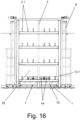
- the work process is as follows: If a die, identified with reference number (25) in Figure 16 , which is to be stored on a shelf (2) is arranged on the transport carriage, the carriage moves to the place of said shelf (2) where the die (25) is to be deposited.
- the invention allows also establishing the lifting of the platform (7) along the columns (6) according to the "Y" axis as the carriage moves towards the corresponding shelf (2) following an "X" axis, such that the corresponding software will establish that the platform (7) is already at the corresponding height upon reaching the shelf (2) on which the die (25) is to be deposited.
- the tables (14) are guided by the guiding means (23) and the corresponding channelings, both of the frame (13) of the platform (7) of the carriage and of the structure consisting of shelves (2) itself, until reaching the point where the die (25) must be deposited, at which time the lifting means (24) fold up until the die (25) is deposited on the profiles (2.1) of the shelves (2).
- Figures 17 and 18 schematically show the tables (14) transitioning from the lifting means (24) being in a lower folding position to being in a raised position.
- the process is similar but in reverse if a die (25) stored in the structure consisting of shelves (2) is to be collected.
- the carriage reaches the corresponding point where it must collect the die (25) and by means of the spindles actuated by the motors (6.2) of the columns (6) it moves its platform (7) vertically according to the "Y" axis until it reaches the corresponding level, at which time the platform (7) of the carriage (1) is automatically fixed to the structure consisting of shelves (2).
- the movement of the platform (7) in "Y” can occur as the carriage (1) moves towards the shelves (2).
- the tables (14) move horizontally according to the "Z" axis and in the lowest position of the lifting means (24) until they are positioned below the die (25).
- the scissors of the lifting means (24) open, raising the upper part (14.1) of the tables (14), and accordingly the die (25). This thereby allows starting the horizontal movement of the tables (14) according to the "Z” axis, but now in the opposite direction, in order to carry the die (25) until it is arranged on top of the frame (13) of the platform (7), and folding the scissors to deposit it on the profiles (13.1) of the frame (13) of the platform (7).
- the lifting means (24) allow the load or die (25) to be lifted with respect to the support on the profiles (2.1) of the shelves (2), such that the upper part of the tables (14) and the die (25) itself are prevented from contacting or brushing against the shelves (2) during the placement and removal of the die.
- the entire loading and unloading process is fully automatic and does not require the participation of operators.
Landscapes
- Engineering & Computer Science (AREA)
- Mechanical Engineering (AREA)
- Warehouses Or Storage Devices (AREA)
Applications Claiming Priority (1)
| Application Number | Priority Date | Filing Date | Title |
|---|---|---|---|
| PCT/ES2020/070239 WO2021209649A1 (es) | 2020-04-14 | 2020-04-14 | Sistema automatico de almacenamiento y recuperacion de troqueles |
Publications (3)
| Publication Number | Publication Date |
|---|---|
| EP4137422A1 true EP4137422A1 (de) | 2023-02-22 |
| EP4137422A4 EP4137422A4 (de) | 2023-12-20 |
| EP4137422B1 EP4137422B1 (de) | 2025-09-03 |
Family
ID=78084050
Family Applications (1)
| Application Number | Title | Priority Date | Filing Date |
|---|---|---|---|
| EP20931343.6A Active EP4137422B1 (de) | 2020-04-14 | 2020-04-14 | Automatisiertes system zum speichern und wiederauffinden von chips |
Country Status (3)
| Country | Link |
|---|---|
| EP (1) | EP4137422B1 (de) |
| ES (1) | ES3053447T3 (de) |
| WO (1) | WO2021209649A1 (de) |
Families Citing this family (1)
| Publication number | Priority date | Publication date | Assignee | Title |
|---|---|---|---|---|
| CN121470080A (zh) * | 2026-01-08 | 2026-02-06 | 邦迪智能科技(上海)股份有限公司 | 能自动换模的3d成型机 |
Family Cites Families (16)
| Publication number | Priority date | Publication date | Assignee | Title |
|---|---|---|---|---|
| US3708077A (en) * | 1971-06-11 | 1973-01-02 | Eaton Yale & Towne | Device means for a vehicle in a warehousing apparatus |
| GB1346027A (en) * | 1972-03-27 | 1974-02-06 | Aplitec Ltd | Automatic storage system |
| JPS6417703A (en) * | 1987-07-10 | 1989-01-20 | Kawasaki Heavy Ind Ltd | Air cargo storing/carrying facility |
| ES2005404A6 (es) | 1987-10-15 | 1989-03-01 | Arrasate S Coop Ltda | Carro robotizado para manipulacion de troqueles entre un juego de prensas y el almacen de troqueles. |
| ES1006554Y (es) | 1988-02-12 | 1989-08-01 | Arrasate, S. Coop. Ltda. | Estructura modular para almacenar troqueles utilizables en prensas de estampacion. |
| EP0654425B1 (de) * | 1993-11-24 | 1998-09-02 | Schenck Handling Systems GmbH | Vorrichtung zum Ein-oder Aus-lagern bzw. Umstapeln von Trägern für Fördergut |
| WO2003004385A2 (de) * | 2001-07-04 | 2003-01-16 | Tgw Transportgeräte Gmbh & Co.Kg. | Transportwagen zum ein- und auslagern von transportgut |
| DE10138619A1 (de) * | 2001-08-13 | 2003-03-20 | Christoph Keller | Vorrichtung zum Transportieren, Entnehmen und Belegen von Werkstückträgern |
| JP4967318B2 (ja) * | 2005-11-18 | 2012-07-04 | ムラテックオートメーション株式会社 | ストッカ |
| JP2009007125A (ja) * | 2007-06-28 | 2009-01-15 | Daifuku Co Ltd | 物品搬送車 |
| JP4378659B2 (ja) * | 2007-06-28 | 2009-12-09 | 株式会社ダイフク | 物品保管庫及びクリーンルーム用の物品保管設備 |
| JP5838549B2 (ja) * | 2010-12-16 | 2016-01-06 | 株式会社Ihi | 物品保管装置及び物品移載方法 |
| EP2566789B1 (de) | 2011-02-21 | 2014-01-15 | SSI Schäfer Noell GmbH Lager-und Systemtechnik | Shuttle für ein lager- und kommissioniersystem |
| US9505556B2 (en) * | 2014-09-03 | 2016-11-29 | Ottos Consultants Ltd. | Storage system using lifting mechanism for collecting containers in desired sequence |
| DE102017219432B4 (de) * | 2017-10-30 | 2025-12-31 | FB Industry Automation GmbH | Regalsystem mit Shuttlefahrzeug |
| CN110745440B (zh) * | 2019-10-30 | 2021-06-01 | 宁波普锐明汽车零部件有限公司 | 智能模具立体库及其控制方法 |
-
2020
- 2020-04-14 ES ES20931343T patent/ES3053447T3/es active Active
- 2020-04-14 WO PCT/ES2020/070239 patent/WO2021209649A1/es not_active Ceased
- 2020-04-14 EP EP20931343.6A patent/EP4137422B1/de active Active
Also Published As
| Publication number | Publication date |
|---|---|
| EP4137422A4 (de) | 2023-12-20 |
| EP4137422B1 (de) | 2025-09-03 |
| WO2021209649A1 (es) | 2021-10-21 |
| ES3053447T3 (en) | 2026-01-22 |
Similar Documents
| Publication | Publication Date | Title |
|---|---|---|
| US4670961A (en) | Process and assembly device intended particularly for body production lines | |
| CN108945933A (zh) | 一种快递机器人用车载自动化立体仓储机构 | |
| US3526327A (en) | Storage and order picking system | |
| JPH0642810U (ja) | 自動倉庫 | |
| CN111319905B (zh) | 一种用于电器元件自动存取的智能仓库 | |
| EP4137422B1 (de) | Automatisiertes system zum speichern und wiederauffinden von chips | |
| CN111283810A (zh) | 汽车保险杠冲孔焊接柔性自动化生产线 | |
| CN114988092B (zh) | 一种齿轮传动移栽车及其运行方法 | |
| CN210524443U (zh) | 升降式交换工作台 | |
| CN202244992U (zh) | 垂直积堆式自动化立体库柜 | |
| CN209442064U (zh) | 一种快递机器人用车载自动化立体仓储机构 | |
| US5643615A (en) | Apparatus and methods for forming workpieces | |
| CN114524217A (zh) | 一种新型智能立式仓库 | |
| CN221369111U (zh) | 大箱底板焊接物料输送系统 | |
| CN202912231U (zh) | 数控立体存储库 | |
| CN218369831U (zh) | 一种用于陶瓷产品的立体存放装置 | |
| CN218200266U (zh) | 一种智能仓储用的穿梭车 | |
| CN210312002U (zh) | 一种立体仓库型材智能存取装置 | |
| DE69302119T2 (de) | Vorrichtung zum Bewegen von Produktion im Inneren von Stapelbereichen eines automatisierten Lagers | |
| CN219135529U (zh) | 一种板材备料台 | |
| CN220843978U (zh) | 自动上下料货仓及自动化生产线 | |
| CN219525573U (zh) | 一种子母托盘堆叠机构 | |
| JP3396252B2 (ja) | 容器グリップヘッド交換装置 | |
| CN223408954U (zh) | 一种平板玻璃装柜机 | |
| CN219771163U (zh) | 一种玻璃自动下料机 |
Legal Events
| Date | Code | Title | Description |
|---|---|---|---|
| STAA | Information on the status of an ep patent application or granted ep patent |
Free format text: STATUS: THE INTERNATIONAL PUBLICATION HAS BEEN MADE |
|
| PUAI | Public reference made under article 153(3) epc to a published international application that has entered the european phase |
Free format text: ORIGINAL CODE: 0009012 |
|
| STAA | Information on the status of an ep patent application or granted ep patent |
Free format text: STATUS: REQUEST FOR EXAMINATION WAS MADE |
|
| 17P | Request for examination filed |
Effective date: 20221109 |
|
| AK | Designated contracting states |
Kind code of ref document: A1 Designated state(s): AL AT BE BG CH CY CZ DE DK EE ES FI FR GB GR HR HU IE IS IT LI LT LU LV MC MK MT NL NO PL PT RO RS SE SI SK SM TR |
|
| P01 | Opt-out of the competence of the unified patent court (upc) registered |
Effective date: 20230517 |
|
| DAV | Request for validation of the european patent (deleted) | ||
| DAX | Request for extension of the european patent (deleted) | ||
| A4 | Supplementary search report drawn up and despatched |
Effective date: 20231122 |
|
| RIC1 | Information provided on ipc code assigned before grant |
Ipc: B65G 1/04 20060101AFI20231116BHEP |
|
| GRAP | Despatch of communication of intention to grant a patent |
Free format text: ORIGINAL CODE: EPIDOSNIGR1 |
|
| STAA | Information on the status of an ep patent application or granted ep patent |
Free format text: STATUS: GRANT OF PATENT IS INTENDED |
|
| INTG | Intention to grant announced |
Effective date: 20250416 |
|
| GRAS | Grant fee paid |
Free format text: ORIGINAL CODE: EPIDOSNIGR3 |
|
| GRAA | (expected) grant |
Free format text: ORIGINAL CODE: 0009210 |
|
| STAA | Information on the status of an ep patent application or granted ep patent |
Free format text: STATUS: THE PATENT HAS BEEN GRANTED |
|
| AK | Designated contracting states |
Kind code of ref document: B1 Designated state(s): AL AT BE BG CH CY CZ DE DK EE ES FI FR GB GR HR HU IE IS IT LI LT LU LV MC MK MT NL NO PL PT RO RS SE SI SK SM TR |
|
| REG | Reference to a national code |
Ref country code: CH Ref legal event code: EP |
|
| REG | Reference to a national code |
Ref country code: DE Ref legal event code: R096 Ref document number: 602020058298 Country of ref document: DE |
|
| REG | Reference to a national code |
Ref country code: IE Ref legal event code: FG4D |
|
| REG | Reference to a national code |
Ref country code: CH Ref legal event code: R17 Free format text: ST27 STATUS EVENT CODE: U-0-0-R10-R17 (AS PROVIDED BY THE NATIONAL OFFICE) Effective date: 20251117 |
|
| REG | Reference to a national code |
Ref country code: NL Ref legal event code: FP |
|
| PG25 | Lapsed in a contracting state [announced via postgrant information from national office to epo] |
Ref country code: NO Free format text: LAPSE BECAUSE OF FAILURE TO SUBMIT A TRANSLATION OF THE DESCRIPTION OR TO PAY THE FEE WITHIN THE PRESCRIBED TIME-LIMIT Effective date: 20251203 |
|
| REG | Reference to a national code |
Ref country code: LT Ref legal event code: MG9D |
|
| PG25 | Lapsed in a contracting state [announced via postgrant information from national office to epo] |
Ref country code: FI Free format text: LAPSE BECAUSE OF FAILURE TO SUBMIT A TRANSLATION OF THE DESCRIPTION OR TO PAY THE FEE WITHIN THE PRESCRIBED TIME-LIMIT Effective date: 20250903 |
|
| PG25 | Lapsed in a contracting state [announced via postgrant information from national office to epo] |
Ref country code: HR Free format text: LAPSE BECAUSE OF FAILURE TO SUBMIT A TRANSLATION OF THE DESCRIPTION OR TO PAY THE FEE WITHIN THE PRESCRIBED TIME-LIMIT Effective date: 20250903 |
|
| PG25 | Lapsed in a contracting state [announced via postgrant information from national office to epo] |
Ref country code: GR Free format text: LAPSE BECAUSE OF FAILURE TO SUBMIT A TRANSLATION OF THE DESCRIPTION OR TO PAY THE FEE WITHIN THE PRESCRIBED TIME-LIMIT Effective date: 20251204 |
|
| PG25 | Lapsed in a contracting state [announced via postgrant information from national office to epo] |
Ref country code: SE Free format text: LAPSE BECAUSE OF FAILURE TO SUBMIT A TRANSLATION OF THE DESCRIPTION OR TO PAY THE FEE WITHIN THE PRESCRIBED TIME-LIMIT Effective date: 20250903 |
|
| PG25 | Lapsed in a contracting state [announced via postgrant information from national office to epo] |
Ref country code: LV Free format text: LAPSE BECAUSE OF FAILURE TO SUBMIT A TRANSLATION OF THE DESCRIPTION OR TO PAY THE FEE WITHIN THE PRESCRIBED TIME-LIMIT Effective date: 20250903 |
|
| REG | Reference to a national code |
Ref country code: ES Ref legal event code: FG2A Ref document number: 3053447 Country of ref document: ES Kind code of ref document: T3 Effective date: 20260122 |
|
| PG25 | Lapsed in a contracting state [announced via postgrant information from national office to epo] |
Ref country code: PL Free format text: LAPSE BECAUSE OF FAILURE TO SUBMIT A TRANSLATION OF THE DESCRIPTION OR TO PAY THE FEE WITHIN THE PRESCRIBED TIME-LIMIT Effective date: 20250903 Ref country code: BG Free format text: LAPSE BECAUSE OF FAILURE TO SUBMIT A TRANSLATION OF THE DESCRIPTION OR TO PAY THE FEE WITHIN THE PRESCRIBED TIME-LIMIT Effective date: 20250903 |
|
| PG25 | Lapsed in a contracting state [announced via postgrant information from national office to epo] |
Ref country code: RS Free format text: LAPSE BECAUSE OF FAILURE TO SUBMIT A TRANSLATION OF THE DESCRIPTION OR TO PAY THE FEE WITHIN THE PRESCRIBED TIME-LIMIT Effective date: 20251203 |
|
| REG | Reference to a national code |
Ref country code: AT Ref legal event code: MK05 Ref document number: 1832838 Country of ref document: AT Kind code of ref document: T Effective date: 20250903 |
|
| PG25 | Lapsed in a contracting state [announced via postgrant information from national office to epo] |
Ref country code: SM Free format text: LAPSE BECAUSE OF FAILURE TO SUBMIT A TRANSLATION OF THE DESCRIPTION OR TO PAY THE FEE WITHIN THE PRESCRIBED TIME-LIMIT Effective date: 20250903 |
|
| PG25 | Lapsed in a contracting state [announced via postgrant information from national office to epo] |
Ref country code: AT Free format text: LAPSE BECAUSE OF FAILURE TO SUBMIT A TRANSLATION OF THE DESCRIPTION OR TO PAY THE FEE WITHIN THE PRESCRIBED TIME-LIMIT Effective date: 20250903 |
|
| PG25 | Lapsed in a contracting state [announced via postgrant information from national office to epo] |
Ref country code: IS Free format text: LAPSE BECAUSE OF FAILURE TO SUBMIT A TRANSLATION OF THE DESCRIPTION OR TO PAY THE FEE WITHIN THE PRESCRIBED TIME-LIMIT Effective date: 20260103 |
|
| PG25 | Lapsed in a contracting state [announced via postgrant information from national office to epo] |
Ref country code: PT Free format text: LAPSE BECAUSE OF FAILURE TO SUBMIT A TRANSLATION OF THE DESCRIPTION OR TO PAY THE FEE WITHIN THE PRESCRIBED TIME-LIMIT Effective date: 20260105 Ref country code: CZ Free format text: LAPSE BECAUSE OF FAILURE TO SUBMIT A TRANSLATION OF THE DESCRIPTION OR TO PAY THE FEE WITHIN THE PRESCRIBED TIME-LIMIT Effective date: 20250903 |
|
| PG25 | Lapsed in a contracting state [announced via postgrant information from national office to epo] |
Ref country code: SK Free format text: LAPSE BECAUSE OF FAILURE TO SUBMIT A TRANSLATION OF THE DESCRIPTION OR TO PAY THE FEE WITHIN THE PRESCRIBED TIME-LIMIT Effective date: 20250903 Ref country code: EE Free format text: LAPSE BECAUSE OF FAILURE TO SUBMIT A TRANSLATION OF THE DESCRIPTION OR TO PAY THE FEE WITHIN THE PRESCRIBED TIME-LIMIT Effective date: 20250903 |
|
| REG | Reference to a national code |
Ref country code: CH Ref legal event code: U11 Free format text: ST27 STATUS EVENT CODE: U-0-0-U10-U11 (AS PROVIDED BY THE NATIONAL OFFICE) Effective date: 20260501 |