EP4137708B1 - Ancre extensible - Google Patents
Ancre extensible Download PDFInfo
- Publication number
- EP4137708B1 EP4137708B1 EP22200871.6A EP22200871A EP4137708B1 EP 4137708 B1 EP4137708 B1 EP 4137708B1 EP 22200871 A EP22200871 A EP 22200871A EP 4137708 B1 EP4137708 B1 EP 4137708B1
- Authority
- EP
- European Patent Office
- Prior art keywords
- hollow shaft
- bolt
- radially expansive
- expansion anchor
- radially
- Prior art date
- Legal status (The legal status is an assumption and is not a legal conclusion. Google has not performed a legal analysis and makes no representation as to the accuracy of the status listed.)
- Active
Links
Images


Classifications
-
- F—MECHANICAL ENGINEERING; LIGHTING; HEATING; WEAPONS; BLASTING
- F16—ENGINEERING ELEMENTS AND UNITS; GENERAL MEASURES FOR PRODUCING AND MAINTAINING EFFECTIVE FUNCTIONING OF MACHINES OR INSTALLATIONS; THERMAL INSULATION IN GENERAL
- F16B—DEVICES FOR FASTENING OR SECURING CONSTRUCTIONAL ELEMENTS OR MACHINE PARTS TOGETHER, e.g. NAILS, BOLTS, CIRCLIPS, CLAMPS, CLIPS OR WEDGES; JOINTS OR JOINTING
- F16B13/00—Dowels or other devices fastened in walls or the like by inserting them in holes made therein for that purpose
- F16B13/04—Dowels or other devices fastened in walls or the like by inserting them in holes made therein for that purpose with parts gripping in the hole or behind the reverse side of the wall after inserting from the front
- F16B13/08—Dowels or other devices fastened in walls or the like by inserting them in holes made therein for that purpose with parts gripping in the hole or behind the reverse side of the wall after inserting from the front with separate or non-separate gripping parts moved into their final position in relation to the body of the device without further manual operation
- F16B13/0891—Dowels or other devices fastened in walls or the like by inserting them in holes made therein for that purpose with parts gripping in the hole or behind the reverse side of the wall after inserting from the front with separate or non-separate gripping parts moved into their final position in relation to the body of the device without further manual operation with a locking element, e.g. wedge, key or ball moving along an inclined surface of the dowel body
-
- F—MECHANICAL ENGINEERING; LIGHTING; HEATING; WEAPONS; BLASTING
- F16—ENGINEERING ELEMENTS AND UNITS; GENERAL MEASURES FOR PRODUCING AND MAINTAINING EFFECTIVE FUNCTIONING OF MACHINES OR INSTALLATIONS; THERMAL INSULATION IN GENERAL
- F16B—DEVICES FOR FASTENING OR SECURING CONSTRUCTIONAL ELEMENTS OR MACHINE PARTS TOGETHER, e.g. NAILS, BOLTS, CIRCLIPS, CLAMPS, CLIPS OR WEDGES; JOINTS OR JOINTING
- F16B13/00—Dowels or other devices fastened in walls or the like by inserting them in holes made therein for that purpose
- F16B13/12—Separate metal or non-separate or non-metal dowel sleeves fastened by inserting the screw, nail or the like
- F16B13/124—Separate metal or non-separate or non-metal dowel sleeves fastened by inserting the screw, nail or the like fastened by inserting a threaded element, e.g. screw or bolt
-
- F—MECHANICAL ENGINEERING; LIGHTING; HEATING; WEAPONS; BLASTING
- F16—ENGINEERING ELEMENTS AND UNITS; GENERAL MEASURES FOR PRODUCING AND MAINTAINING EFFECTIVE FUNCTIONING OF MACHINES OR INSTALLATIONS; THERMAL INSULATION IN GENERAL
- F16B—DEVICES FOR FASTENING OR SECURING CONSTRUCTIONAL ELEMENTS OR MACHINE PARTS TOGETHER, e.g. NAILS, BOLTS, CIRCLIPS, CLAMPS, CLIPS OR WEDGES; JOINTS OR JOINTING
- F16B13/00—Dowels or other devices fastened in walls or the like by inserting them in holes made therein for that purpose
- F16B13/04—Dowels or other devices fastened in walls or the like by inserting them in holes made therein for that purpose with parts gripping in the hole or behind the reverse side of the wall after inserting from the front
- F16B13/08—Dowels or other devices fastened in walls or the like by inserting them in holes made therein for that purpose with parts gripping in the hole or behind the reverse side of the wall after inserting from the front with separate or non-separate gripping parts moved into their final position in relation to the body of the device without further manual operation
- F16B13/0833—Dowels or other devices fastened in walls or the like by inserting them in holes made therein for that purpose with parts gripping in the hole or behind the reverse side of the wall after inserting from the front with separate or non-separate gripping parts moved into their final position in relation to the body of the device without further manual operation with segments or fingers expanding or tilting into an undercut hole
-
- F—MECHANICAL ENGINEERING; LIGHTING; HEATING; WEAPONS; BLASTING
- F16—ENGINEERING ELEMENTS AND UNITS; GENERAL MEASURES FOR PRODUCING AND MAINTAINING EFFECTIVE FUNCTIONING OF MACHINES OR INSTALLATIONS; THERMAL INSULATION IN GENERAL
- F16B—DEVICES FOR FASTENING OR SECURING CONSTRUCTIONAL ELEMENTS OR MACHINE PARTS TOGETHER, e.g. NAILS, BOLTS, CIRCLIPS, CLAMPS, CLIPS OR WEDGES; JOINTS OR JOINTING
- F16B35/00—Screw-bolts; Stay-bolts; Screw-threaded studs; Screws; Set screws
- F16B35/005—Set screws; Locking means therefor
-
- F—MECHANICAL ENGINEERING; LIGHTING; HEATING; WEAPONS; BLASTING
- F16—ENGINEERING ELEMENTS AND UNITS; GENERAL MEASURES FOR PRODUCING AND MAINTAINING EFFECTIVE FUNCTIONING OF MACHINES OR INSTALLATIONS; THERMAL INSULATION IN GENERAL
- F16B—DEVICES FOR FASTENING OR SECURING CONSTRUCTIONAL ELEMENTS OR MACHINE PARTS TOGETHER, e.g. NAILS, BOLTS, CIRCLIPS, CLAMPS, CLIPS OR WEDGES; JOINTS OR JOINTING
- F16B37/00—Nuts or like thread-engaging members
- F16B37/12—Nuts or like thread-engaging members with thread-engaging surfaces formed by inserted coil-springs, discs, or the like; Independent pieces of wound wire used as nuts; Threaded inserts for holes
- F16B37/122—Threaded inserts, e.g. "rampa bolts"
Definitions
- the present invention relates to an expansion anchor of the type in which a portion of a hollow shaft is bulged by screwing of a bolt.
- Expansion anchors are used to attach various members such as fittings to stony structures made of concrete or the like, as in the case where various members are suspended from the inner surface of a tunnel, for example.
- expansion anchors There are various types of expansion anchors.
- the tip end of a hollow shaft (anchor body) is divided by a plurality of circumferentially separated longitudinal slits to provide an radially expansive portion (expansion portion), and the radially expansive portion is bulged utilizing a wedging action caused by screwing of a bolt.
- expansion anchor of the type that utilizes, instead of a bolt, a pin with a tapering tip portion having a progressively decreasing diameter toward the tip end.
- the pin is impacted with a hammer for insertion into the hollow shaft.
- JP 2004-218421 A a ball made of metal is inserted into a radially expansive portion for bulging the radially expansive portion due to an expanding action caused by the ball.
- Microfilm of JP H4-272019U also discloses a similar configuration.
- Japanese Registered Utility Model No. 3007126 and microfilm of JP S52-6970 U disclose use of a fusiform member as a radially expanding member instead of the ball.
- JP S51 24450 A discloses an expansion bolt having a shank with a thread at one end and a frusto-conical expander portion at the other end, and a deformable sleeve of metal or plastics surrounding the shank so as to be expanded when the portion is drawn through the sleeve by turning of a nut or threaded bush engaging the thread, a closed hollow space is defined between the inner surface of the sleeve and the outer surface of the shank which is filled with small hard balls, e.g. of steel, which transmit forces from the expander portion evenly to the entire inner sleeve surface so that the sleeve is expanded.
- small hard balls e.g. of steel
- the expansion anchors disclosed in the patent documents and the hit-type expansion anchors provide a withdrawal resistance by expanding the radially expansive portion located at the tip end of the hollow shaft into a flaring shape and pressing the radially expansive portion against a pre-formed hole.
- the withdrawal resistance of the conventional expansion anchors is fixed theoretically.
- a troublesome problem regarding an expansion anchor is a phenomenon called cone-type failure wherein a portion of concrete centered around the expansion anchor at the installation region comes off in the form of a cone. Such a cone-type failure occurs due to the expansion of the radially expansive portion of the anchor. Therefore, in order to prevent the cone-type failure, an expansion anchor is designed in a manner such that the radially expansive portion thereof do not expand excessively, which is one of the detrimental factors in enhancing the withdrawal resistance.
- a more troublesome problem is that, when an anchor is engaged into the ceiling of a concrete tunnel for example, the weight of a workpiece acts as a downward load on the expansion anchor, and this downward load may cause cone-type failure. In other words, even if there appears no problem at the time of installation, a cone-type failure occurs as a delayed failure upon lapse of time.
- the present invention which has been conceived in light of the aforementioned circumstances, provides an expansion anchor that keeps a high withdrawal resistance while also providing a high functionality for preventing a cone-type failure.
- the present invention includes various structural features as set out in claim 1. Typical aspects thereof are identified below.
- the invention provides an expansion anchor which includes a hollow shaft insertable, from a tip end thereof, into a pre-formed hole formed in an installation region, and a bolt to be screwed into the hollow shaft from outside the installation region, wherein the hollow shaft is formed with a radially expansive portion, that is weakened to be bulgeable, at a portion of the hollow shaft within the pre-formed hole and short of the tip end of the hollow shaft, and the hollow shaft is internally provided with a radially expanding action member that pushes the radially expansive portion radially outward in response to pushing action caused by screwing of the bolt into the hollow shaft.
- the hollow shaft does not need to be open at both ends if at least its base end (to be located outside of the installation region) is open. Therefore, the tip end to be inserted into the pre-formed hole may have a solid structure. Further, a plurality of radially expansive portions can be provided. These are the major features.
- the expansion anchor may usually have a perfect circular shape, but its shape is not necessarily limited to a perfect circle.
- the device may comprise a structure in which the entire hollow shaft or only the radially expansive portion is formed in a non-perfect circle such as an ellipse or a polygon.
- a non-perfect circular shape also include a shape that basically follows a perfect circle but has two flat faces which are parallel to each other.
- the pre-formed hole is generally formed in a perfect circular shape at the installation region using a rotating drill. However, when the hollow shaft has a non-perfect circular shape, the pre-formed hole may be processed into a non-perfect circle corresponding to the shape of the hollow shaft.
- the radially expansive portion of the hollow shaft is formed with a plurality of axially elongated slits that are circumferentially spaced from each other.
- a portion of the hollow shaft in which the slits are formed serves as a radially expansive portion.
- the number of the slits may be selected depending on the outer diameter or thickness of the hollow shaft. In general, three to six slits may be usually formed.
- the slits in a group may be arranged at circumferentially regular or irregular intervals.
- the radially expanding action member includes a multiplicity of metal balls, and the radially expansive portion is allowed to bulgingly deform due to the balls moving radially outward in group in response to a push from the bolt.
- the balls in the group may be entirely equal in diameter, or they may include a plurality of diametrically different balls.
- the radially expansive portion may have an axial length that is at least twice an outer diameter of the hollow shaft.
- One major feature is that the length of the radially expansive portion can be set to be extended.
- a member such as a fitting may be attached to the expansion anchor.
- the hollow shaft is configured such that the other end is exposed outside the installation region, at least a portion of the hollow shaft that is exposed outside of the installation region is formed with fixing threads, and the fixing male screw is engageable with a nut for mounting another member.
- the radially expansive portion is located at a position short of the tip end of the hollow shaft. Therefore, the radially expansive portion does not expand into a flaring form but bulges expansively in a direction orthogonal to the axis. This bulging portion comes into biting engagement with the pre-formed hole at the installation region (made of concrete), consequently providing a resistance against withdrawal.
- One feature of the present invention resides in that the length of the radially expansive portion can be increased.
- the radially expansive portion having an increased length can come into deep biting engagement with the installation region, thereby contributing greatly to an increase in withdrawal resistance (namely, fastening strength).
- the expansion anchor is particularly useful as a fastening tool to suspend a member from a concrete ceiling of a tunnel or building. Furthermore, according to the present invention, when the hooking force of the radially expansive portion reduces due to a timewise damage of the installation region for example, the withdrawal resistance may be restored by screwing the bolt to expand the radially expansive portion. Therefore, it is easy to adjust the torque to keep the withdrawal resistance at an appropriate value. In the case where the bolt has slided down, it is preferable to expand the radially expansive portion again after pushing the bolt back to the original depth.
- the radially expanding action member can be easily retreated by screwing back the bolt, it is easy to pull out the expansion anchor, which has been once attached, against the elastic force of the radially expansive portion. Accordingly, it is also easy to remove an unnecessary anchor and replace it with a new one.
- the slits formed according to the invention as a means for forming the radially expansive portion enables the radially expansive portion to bulge in a reliable manner. Moreover, when the radially expansive portion is divided by the slits into a plurality of circumferentially separated sections, a specific one or ones of the sections are more likely to bulge for more readily coming into biting engagement with the installation region to provide better hooking to the installation region. Accordingly, it is possible to provide a high fastening strength can be reliably obtained while preventing cone-type failure.
- Metal balls are widely used in various fields such as bearings, and various types of metal balls are commercially available. Therefore, it is possible to suppress the manufacturing cost due to ready availability of metal balls requiring no dedicated manufacturing apparatus.
- the metal balls come into point contact with the radially expansive portion from the inside, so that the entire circumference of the radially expansive portion is not pressed uniformly. Instead, only specific circumferential positions of the radially expansive portion are pressed outward by the metal balls. As a result, the area of engagement of the radially expansive portion with the installation region is reduced, so that the radially expansive portion can easily come into biting engage with the installation region. In other words, the radially expansive portion can easily come into deep engagement with the installation region in the manner of biting into the installation region. In this way, it possible to provide a high hooking force while suppressing the compressive force against the installation region.
- the metal balls as the radially expanding action member is advantageous in providing a high fastening strength without causing cone-type failure.
- the length (axial length) of the radially expansive portion may be selected depending on the required withdrawal resistance.
- the radially expansive portion has an axial length that is at least twice an outer diameter of the hollow shaft, the radially expansive portion can be bulged reliably, so that a high withdrawal resistance (fastening strength) can be secured more reliably.
- a checking operation may be performed by rotating the bolt using a torque wrench. However, if a suspended member has to be removed every time the bolt is rotated using a torque wrench, the checking operation becomes troublesome.
- the head of the bolt pressing the radially expanding action member can be kept exposed outside of the installation region, so that the bolt can be rotated using a torque wrench while a member such as a ceiling panel or a ceiling frame is kept suspended by the expansion anchor. Accordingly, a maintenance operation can be performed very easily for checking whether or not the withdrawal resistance of the expansion anchor is kept at a predetermined value and restoring the withdrawal resistance which has dropped.
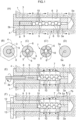
- An expansion anchor includes a hollow shaft 3 to be inserted into a pre-formed hole 2 in an installation region 1 made of concrete.
- an end that will enter the pre-formed hole 2 is defined as a tip end 3a, and an opposite end is defined as a base end 3b.
- the base end 3b of the hollow shaft 3 is provided with a flange (or head) 4 having a hexagonal shape or a circular shape.
- the hollow shaft 3 is formed with a hole 5 over the entire length thereof, and the hole 5 has a small-diameter portion 5a within a certain range from the tip end 3a.
- the tip end 3a may have a solid structure in which the small-diameter portion 5a of the hole 5 is eliminated.
- the hole 5 may have a constant diameter over the entire length thereof, and the tip end 3a is closed with a plug.
- the hollow shaft 3 may also be formed by stretching a hollow coil pipe with a small-diameter hole. In this case, the inner diameter of the material coil pipe remains as the diameter of the small-diameter portion 5a, whereas the other portion of the hollow shaft is diametrically enlarged by drilling or the like.
- the material of the hollow shaft 3 may be selected as needed. When high durability and rust-resistance are required as in the case of anchors for tunnels, it is preferable to use a hollow shaft made of stainless steel. Steel that has undergone surface treatment such as plating is also preferable
- the hollow shaft 3 short of the tip end 3a there are formed four axially elongated slits 6 at regular circumferential intervals.
- the portion of the hollow shaft in which the slits 6 are formed serves as an radially expansive portion 7 that is bulgeable in a direction orthogonal to the axis. Therefore, the slits 6 do not extend into the tip end 3a of the hollow shaft 3. Further, the slits 6 communicate with the inside and outside of the hollow shaft 3.
- the slits 6 may be machined using a milling cutter, for example.
- the number of the slits 6 can be selected as desired. In the example shown in FIG. 1 (C'), six slits 6 are formed.
- the axial length of the radially expansive portion 7 is set to be about twice the outer diameter of the hollow shaft 3. When the radially expansive portion 7 has a small thickness, the radially expansive portion 7 can be easily deformed even if its length is shorter than twice the outer diameter of the hollow shaft 3.
- the hole 5 of the hollow shaft 3 is formed with a female screw 8 in a portion (toward the base end 3b) short of the radially expansive portion 7, and a hexagonal-socket bolt 9 is screwed into the female screw 8 from the outside (the female screw 8 may extend into the radially expansive portion 7).
- a multiplicity of metal balls (steel balls) 10 as an example of radially expanding action member, are accommodated between the bolt 9 and the tip end 3a.
- the outer diameters of the balls 10 are set to be slightly smaller than the inner diameter of the hole 5, and in the illustrated example, the balls 10 have an equal outer diameter. It will be appreciated that the outer diameter of the balls 10 may be set to be substantially equal to the inner diameter of the hole 5.
- the outer diameter of the hollow shaft 3 and the inner diameter of the hole 5 may be set as desired. In other words, the thickness of the hollow shaft 3 may be set as desired.
- a method of using the expansion anchor is similar to a conventional method. As shown in FIG. 1(E) , the hollow shaft 3 is fitted into the pre-formed hole 2 in the installation region 1, and then the bolt 9 is screwed thereinto using a hexagonal bit 11. This causes the group of balls 9 to be moved in a chain reaction manner. The adjacent balls 10 are in contact with each other, and therefore, the balls 10 also tend to move radially of the hollow shaft 3. As a result, the radially expansive portion 7 deforms expansively over a long range and engages with the pre-formed hole 2 in the installation region 1.
- the radially expansive portion 7 is shown to expand into a plateau shape by solid lines in FIGS. 1(E) and 1(F) .
- the radially expansive portion 7 is more likely to bulge in a mountain-like shape (or a bow shape) as indicated by a chain line in FIG. 1(E) because the balls 10 pressing against one another act such that the balls 10 located at weaker portions are pressed more strongly.
- the balls 10 come into point contact with the radially expansive portion 7
- the ball 10 that comes into contact with the weakest portion of the radially expansive portion 7 is most strongly pressed by the other balls 10, so that the radially expansive portion 7 is deformed in a mountain-like shape.
- the radially expansive portion 7 When the length of the radially expansive portion 7 is reduced, the radially expansive portion 7 inevitably bulges in a mountain-like shape or a bow shape.
- the radially expansive portion 7 is divided into a plurality of sections by the slits 6. It is more likely that the weakest one of these sections is concentratively bulged rather than all sections bulging uniformly. Therefore, in general, bulging may occur only at one circumferential position of the radially expansive portion 7.
- a radially expansive portion is denoted by a reference numeral 7a.
- the leading end of the radially expansive portion 7' moves as indicated by an arrow 7b, and a pressing force (compressive load) acts on the installation region 1 made of concrete as indicated by the arrow 7b.
- a boundary may be generated in the installation region 1 made of concrete between a portion pressed strongly by the radially expansive portion 7a and a portion not so pressed.
- the radially expansive portion 7a applies a pressing force in the direction 7b which is inclined relative to the anchor axis, and it is also speculated that the boundary is likely to form a conical surface, which may promote cone-type failure.
- the radially expansive portion 7 is deformed into a mountain-like shape or the like. It is thus speculated that the radially expansive portion 7 engages with the installation region 1 while biting into the structural material instead of strongly pressing against the installation region 1. In other words, it is considered that the expansion anchor is hooked to the pre-formed hole due to biting rather than staying in the pre-formed hole due to friction. This makes it possible to achieve a high withdrawal resistance while preventing cone-type failure.
- the radially expansive portion 7 bulges in a direction orthogonal to the axis of the hollow shaft 3, so that a boundary may not be formed in the installation region 1 between a portion subjected to a strong pressing force and a portion not subjected to a strong pressing force. Instead, the pressing force (compressive stress) acting on the installation region 1 changes gradually in the axial direction, thereby contributing greatly to the prevention of cone-type failure.
- the hexagonal bit 11 is attached to a torque wrench.
- the pushing force of the radially expansive portion 7 against the pre-formed hole 2 is proportional to the screwing torque of the bolt 9. Therefore, when a predetermined screwing torque is reached by screwing the bolt 9 with a torque wrench, rotation of the bolt is stopped.
- the bolt 9 has deeply entered into the female screw hole 8 when the radially expansive portion 7 is bulged. Therefore, a member 13 can be fixed to the base end surface of the hollow shaft 3 by screwing a fastening bolt 12 into the female screw hole 8. Accordingly, a state has to be achieved in which the bolt 9 enters entirely into the female screw hole 8 to allow another bolt to be further screwed into the female screw hole 8 from the outside.
- the use mode of the expansion anchor may be set as desired depending on the conditions of the installation region.
- a suspension bolt is screwed into the hollow shaft 3 from below, and various members such as a ceiling panel is suspended by the suspension bolt (this example will be described later).
- the length of the radially expansive portion 7 is set as desired depending on the length of the hollow shaft 3, required withdrawal resistance, or the like.
- the base end 3a of the hollow shaft 3 is provided with no flange, but the second expansion anchor has otherwise the same structure as the first expansion anchor.
- the radially expansive portion 7 is shown to bulge in a trapezoidal shape. In reality, however, the radially expansive portion 7 is more likely to bulge in a mountain-like shape as indicated by the chain line in FIG. 1(E) .
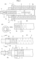
- the third expansion anchor shown in FIG. 2(B) and the fourth expansion anchor shown in FIG. 2(C) share a common structure in which the outer circumference of the hollow shaft 3 is formed with an engaging male screw 15 for engagement with the pre-formed hole.
- a flange 4 is formed at the base end 3b of the hollow shaft 3, whereas a straight structure of the hollow shaft without a flange 4 is obtained in the example shown in FIG. 2(C) .
- the engaging male screw 15 may have a pitch that is plural times larger than the thread width for facilitating the inserting engagement into the pre-formed hole 2 in the installation region 1.
- a plurality of threads having different heights may also be formed.
- the engaging male screw 15 when the flange 4 as shown in FIG. 2(B) is formed in a polygonal shape such as a hexagonal shape that can be rotated using a spanner (wrench), the hollow shaft 3 can be easily screwed into the pre-formed hole 2.
- the engaging male screw 15 is formed only up to a position short of the radially expansive portion 7.
- the engaging male screw 15 may be formed to extend also over the entirety of the radially expansive portion 7.
- the engaging male screw 15 formed to extend over the radially expansive portion 7 is expected to remarkably improve the withdrawal resistance because the engaging male screw 15 comes into strong biting engagement with the pre-formed hole 2 due to bulging of the radially expansive portion 7.
- each annular projection 16 has a crosssectional shape of a right-angled triangle with its inclined surface oriented toward the tip end 3a, consequently providing a high withdrawal resistance.
- the annular projections 16A may be replaced with a spiral projection.
- the outer circumference of the radially expansive portion 7 may be knurled.
- a fixing male screw 16 for screwing engagement with a nut 17 is formed within a certain range on the base end side of the hollow shaft 3. Therefore, the fixing male screw 18 serves as a metric screw thread.
- a member 13 is formed with an attachment hole 19 in which the fixing male screw portion 16 is fitted, and the member 13 is pressed against and fixed to the surface of the installation region 1 using the nut 17. It is unnecessary to insert the bolt 9 entirely into the hollow shaft 3, so that a bolt with a head can be used as the bolt 9. Moreover, the radially expansive portion 7 may be made to bulge in response to operating the bolt 9 while the member 13 is fixed.
- the seventh expansion anchor shown in FIG.3 (B) is a modified example of the sixth expansion anchor.
- a flange 4 is provided on the hollow shaft 3
- a fixing male screw 16 is formed outwardly from the flange 4
- an engaging male screw 15 is formed on a side opposite to the fixing male screw 16.
- the flange 4 may preferably have a polygonal shape such as a hexagonal shape.
- an engaging male screw 15 is formed on the outer circumference of the hollow shaft 3, and an engaging hole 20 for fitting engagement with a polygonal bit 11 having a hexagonal shape or the like is formed at the base end of the hollow shaft 3. Therefore, a flange 4 may be unnecessary.
- the bolt 9 for bulging the radially expansive portion 7a has a hexagonal socket, and the bolt 9 is set to be exposed to the outside of the hollow shaft 3 even in the state where the radially expansive portion 7 is bulged.
- the member 13 is fitted over the bolt 9 and fixed thereto using a nut 17. Therefore, in this expansion anchor, the bolt 9 for bulging the radially expansive portion 7 is used to attach (fix) the member 13. Further, a rotational operation (torque adjustment) of the bolt 9 can be easily performed by loosening the nut 17.
- the nut 17 also serves to prevent the bolt 9 from loosening.
- a hole 5 is formed in the hollow shaft 3 over the entire length thereof, and a female screw 8 is formed in the hole 5 over the entire length thereof, and a stopper bolt 21 is screwed into the hollow shaft from the tip end thereof.
- this expansion anchor use may be made of a pipe for forming the hollow shaft 3, thus contributing to a cost reduction.
- Female screws 8 may be formed only on two sides flanking the radially expansive portion 7.
- a milling cutter 22 that is machining the slits 6. Although the milling cutter 22 is shown to be moved in the figure, the hollow shaft 3 may be moved instead.
- a fixing male screw 16 such as shown in FIG. 3(A) may be formed at the base end 3b of the hollow shaft 3 in this expansion anchor as well.
- Punching press may be used as a means for forming the slits 6. More specifically, the slits 6 can be formed through punching by inserting a grooved rod into the hollow pipe 3 and moving a punch toward the groove of the rod from the outside. The tip end of the hollow pipe 3 may be closed by crushing or squeezing deformation instead of screwing a stopper bolt 21.
- the outer circumferential surface of the radially expansive portion 7a is formed with wavy irregularities at a fine pitch.
- This expansion anchor is similar to the expansion anchor shown in FIG. 2(D) , but differs from the expansion anchor shown in FIG. 2(D) in that the irregularities are provided by forming a multiplicity of grooves on the radially expansive portion 7. Therefore, the projections of the irregularities does not provide resistance to insertion of the hollow pipe into the pre-formed hole 2. Nevertheless, the projections come into biting engagement with the pre-formed hole 2 when the radially expansive portion 7 bulges, thereby providing a high withdrawal resistance.
- two radially expansive portions 7 are formed as axially separated from each other. With this configuration, the two radially expansive portions 7 press against the pre-formed hole 2 as axially spaced from each other. Therefore, a very high withdrawal resistance may be expected. Three or more radially expansive portions 7 may be formed at positions that are axially separated from one another. Further, the plurality of radially expansive portions 7 may differ from each other in length.
- diametrically different balls 10 are used as the radially expanding action member.
- the group of the balls 10 can be caused to press against the inner surface of the radially expansive portion 7 in a distributed manner as much as possible, so that the plurality of sections divided by the slits 6 are easy to bulge individually.
- a multiplicity of (a plurality of) bowl-shaped elements 24 that overlap one another are used as the radially expanding action member.
- the outer circumference and inner circumference of the bowl-shaped element 24 are respectively formed into tapered surfaces 25 and 26 that are both inclined in the same direction.
- the inclination angle of the inner tapered surface 25 is smaller than the inclination angle of the outer tapered surface 26.
- a portion other than the central portion is divided by a plurality of (four) slits that extend radially. Therefore, the bowl-shaped elements 24 are bulgeable to increase its outer diameter.
- each of the bowl-shaped elements 24 deforms expansively, thereby causing the radially expansive portion 7 to bulge.
- the outer circumference of each of the bowl-shaped elements 24 is convexly curved in cross section to come into line contact with the radially expansive portion 7.
- the radially expanding action member comprises a group of discontinuous rings 27 each bent into an annular shape, and balls (steel balls) 28 each arranged between the adjacent rings 27.
- the rings 27 are formed by bending a wire having a circular cross section substantially into a circular form. However, since one end of the wire is not connected to the other end, the ring 27 deforms expansively under pressure from the balls 28.
- the radially expansive portion 7 can be expanded uniformly in the circumferential direction by the rings 27. Therefore, it is expected that the radially expansive portion 7 is prevented from coming into localized contact with the pre-formed hole 2, consequently providing a very high withdrawal resistance.
- a rod 19 is arranged between the bolt 9 and the balls 10. Therefore, the bolt 9 may be shortened, and the time needed for machining the female screw hole 8 can be reduced.
- a wavy element 30 that is bent into a zigzag manner in the axial direction is used as the radially expanding action member.
- the wavy element 30 is divided into four equal sections in the circumferential direction (or may be divided into three equal sections or five or more equal sections). Therefore, when the wavy element 30 is pressed by the bolt 9, its outer diameter increases due to a reduction of its length, consequently causing the radially expansive portion 7 to bulge.
- a stopper rod 31 is provided in a portion surrounded by the wavy element 30. Due to the presence of this stopper rod 31, the wavy element 30 deforms to increase its outer diameter.
- the stopper rod 31 is integrally or separately formed on the bolt 9, and slides in a hole 32 formed in the tip end 3a of the hollow shaft 3 when the bolt 9 is screwed in. In this expansion anchor as well, the sections divided by the slits 6 can be bulged uniformly.
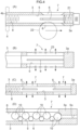
- FIG. 6 specifically shows an exemplary use of the expansion anchor shown in FIG. 3 (A) .
- the expansion anchor is applied to a ceiling portion 1' of a tunnel, for example, and the fixing male screw 16 provided at the base end of the hollow shaft 3 is exposed downward from the ceiling surface.
- An upper piece 33a of a channel suspension fitting 33 is fixed to the ceiling surface using the nut 17, and a suspension bolt 34 is attached to the lower piece 33b of the suspension fitting 33.
- the suspension bolt 34 is used to suspend a ceiling panel or a ceiling frame.
- a socket bolt in which a hexagonal hole is formed in its head is used as the bolt 9 for expanding the radially expansive portion 7, and the head is exposed downward from the ceiling surface (a bolt with a polygonal head can also be used) . It is possible to determine, by rotating the bolt 9 with a torque wrench 35, whether or not the hollow shaft 3 retains an appropriate withdrawal resistance. In this case, when the torque wrench 35 indicates a predetermined value of measurement with the bolt 9 kept non-rotated, an appropriate withdrawal resistance is still retained, so that it is not necessary to take any specific countermeasure.
- the bolt 9 rotates before the measurement of the torque wrench 35 reaches the predetermined value, the biting force of the radially expansive portion 7 against the installation region 1 may have decreased. Therefore, the bolt 9 is rotated until the measurement of the torque wrench increases to the predetermined value.
- the provision of the fixing male screw 16 at the base end of the hollow shaft 3 enables the maintenance of the expansion anchor (adjustment of withdrawal resistance) without removing the suspension fitting 33. Therefore, the maintenance can be performed easily and efficiently.
- a bolt 9 for expanding the radially expansive portion 7 use may be made of a hexagonal-socket bolt having no enlarged head or a bolt with a quadrangular head the circumcircle of which has a diameter equal to or smaller than the outer diameter of the screw thread.
- the use of such a bolt is advantageous in that it does not affect screwing of the nut 17.
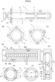
- FIG. 7 shows the test.
- FIGS. 7(A) and 7(B) show samples that were used in the test. The samples were similar to the first expansion anchor.
- the outer diameter was 10 mm
- the entire length was 60 mm
- the inner diameter of the hollow shaft was about 6 mm
- a 8-mm bolt was used as the bolt 9 (the inner diameter of the pre-formed hole of a 8-mm female screw corresponded to the inner diameter of the hollow shaft).
- the radially expansive portion 7 had a length of about 25 mm, the hollow shaft 3 had a constant diameter over the entire length thereof, and the tip end was closed.
- a portion of about 8 mm at the tip end was squeezed, and therefore, the radially expansive portion 7 was shorter than that of the A type.
- a plurality of diametrically different steel balls were used as the radially expanding action member. More specifically, one ball having an outer diameter of 6 mm, three balls having an outer diameter of 4.5 mm, three balls having an outer diameter of 5 mm, and one ball having an outer diameter of 6 mm were arranged in this order from the bolt 9 side.
- a conventional product (commercially available product) C shown in FIG. 7(C) was used as a comparative example.
- this conventional product C the entire length and outer diameter were the same as those of the two samples (60 mm, 10 mm), and four slits C2 were formed in the tip end side of a hollow shaft C1 to be open at the tip end face.
- a portion in which the slits were formed was an radially expansive portion C3 to be expanded into a flaring manner.
- a pin C4 was inserted into the hollow shaft C1 from the base end.
- the pin C4 had a tapering tip end. When the pin C4 was hit into the radially expansive portion C3, the radially expansive portion C3 was expanded. Therefore, the withdrawal resistance of this comparative example C became constant.
- FIG. 7(E) shows the results. Specifically, in FIG. 7(E) , the horizontal axis F indicates the screwing torque of the bolt 9, whereas the vertical axis S indicates the withdrawal resistance.
- a concrete block was used as a target product serving as the installation region.
- A1 was an A type in which the outer circumference of the radially expansive portion 7 was knurled, and A2 was an noraml A type in which the outer circumference of the radially expansive portion 7 was smooth.
- B1 was a B type in which the outer circumference of the radially expansive portion 7 was knurled, whereas B2 was a normal B type in which the outer circumference of the radially expansive portion 7 was smooth. Knurling was performed in an inclined lattice pattern with a fine pitch.
- the graph in FIG. 7(E) clearly shows that the withdrawal resistance increases with an increase in the screwing torque of the bolt 9. It can be understood from these results that the withdrawal strength can be controlled to a desired level by controlling the torque of the bolt 9. It can also be understood that the withdrawal resistance increased due to knurling, and there was no significant difference between the A type and the B type.
- the graph in FIG. 7(D) shows relationship between the amount of shift of the expansion anchor and the withdrawal resistance when the expansion anchor was pulled using a drawing test machine. Specifically, in the graph in FIG. 7(D) , the horizontal axis indicates an axial shift, while the vertical axis indicates a withdrawal resistance.
- the test used an A1 type bolt 9 that was screwed at 20 KNm, an A1 type bolt 9 that was screwed at 8 KNm, and a comparative example C.
- the withdrawal resistance of the anchor had a peak value, and the withdrawal resistance decreased with an increase of drawn amount after exceeding the peak value. Such a result was predictable.
- a multiplicity of diametrically larger balls having substantially the same diameter as the inner diameter of the radially expansive portion 7 are arranged, and a plurality of (e.g., four to six) diametrically smaller balls are arranged between adjacent ones of the diametrically larger balls generally at an axial center of the radially expansive portion 7.
- a plurality of diametrically smaller balls are arranged between adjacent ones of the diametrically larger balls generally at an axial center of the radially expansive portion 7.
- auxiliary members 36 are inserted into the radially expansive portion 7, so that the radially expansive portion 7 is caused to bulge via the auxiliary members 36.
- the auxiliary members 36 are arranged in corresponding relation to and without any circumferential shift from the sections of the radially expansive portion 7 divided by the slits, and outward protrusions 36a are provided at axially shifted positions on the auxiliary members 36 respectively.
- the auxiliary members 36 have such a strength that they do not easily deform. When the group of the balls 10 are pushed by a bolt, the auxiliary members 36 are radially pushed, and the respective sections of the radially expansive portion 7 are bulged due to the protrusions 36a of the auxiliary members 36.
- a nineteenth expansion anchor shown in FIG. 8(E) at least the radially expansive portion 7 is formed in an elliptic shape, and four slits 6 are formed to circumferentially separate thin portions and thick portions.
- the thin portions are concentratively deformed, so that the radially expansive portion 7 can be easily bulged in a symmetrical manner.
- the balls come into contact with the thin portions at axially separated positions. Therefore, even when the radially expansive portion 7 is bulged in a symmetrical manner, the bulges are shifted in the axis direction.
- the slits 6 are formed at uneven intervals in the radially expansive portion 7 which is perfectly circular, thereby providing easily deformable zones in the radially expansive portion 7. In this case as well, so that the radially expansive portion 7 can be easily bulged in a symmetrical manner.
- a twenty-first expansion anchor shown in FIG. 8(G) two pins 37m 38 are inserted into the hollow shaft 3 at a forward position and a rearward position, respectively, and a plurality of balls 10 are arranged between the two pins.
- the pins 37, 38 are formed into a bullet shape having a tapering tip end, and they are arranged such that their tip ends face each other. Therefore, when the rear side pin 38 is pushed using a bolt, the balls 10 are rearranged into a circumferential array due to the clamping action of the pins 37, 38 while moving outward orthogonally to the axis in such an array. Accordingly, the radially expansive portion 7 can be made to bulge accurately at a predetermined position.
- the number of the balls 10 may be set to be three to ten, for example.
- the bolt 9 cannot be further screwed, consequently preventing the radially expansive portion 7 from bulging excessively.
- the maximum screwing torque of the bolt 9 can also be controlled.
- the tip ends of the pins 37, 38 may be conical or frustoconical, or may be curved to be outwardly concave as opposed to the illustrated expansion anchor.
- FIG. 8(G) and the features shown in FIG. 8(E) or 8(F) may be combined for causing the radially expansive portion 7 to readily bulge at two opposite positions that are separated by 180 degrees. It is also possible to use three pins and arrange balls 10 between the adjacent pins. In this case, two radially expansive portions 7 are provided as axially separated from each other, so that the two radially expansive portions 7 are separaly expansive using the balls. Therefore, the expansion anchor shown in FIG. 8(A) may be realized easily. Use may be made of four or more pins for bulging at three or more axially different portions.
- an annular groove 39 is formed in the outer circumferential surface of the pin 38 at an rear end portion, and an O-ring (or a rubber ring) 40, which is an example of a removal restraining means, is fitted in the annular groove 39.
- the O-ring 40 is fitted into the hollow shaft 3 in an elastically deformed state, so that it does not remove easily. Therefore, the balls 10 are prevented from falling out due to careless handling during assembly. Even when the bolt 0 is removed after the installation, the pins 37, 38 and the balls 10 do not fall out.
- the present invention may provide various other expansion anchors in addition to the above-described expansion anchors.
- the outer circumferential surface of the radially expansive portion may be provided with a multiplicity of projections.
- a member such as a suspension fitting may be welded in advance to the hollow shaft.
- the hollow shaft, the radially expanding action member and the bolt may be made of a resin if there is no problem with respect to thermal resistance.
- a plug made of a soft material such as rubber, for example may be inserted into the hollow shaft.
- the plug is crushed by the bolt, so that it does not pose any problem with respect to the function of pressing against the balls.
- the plug is held inside the hollow shaft, so that the radially expanding action member namely the balls can be prevented from falling out.
- a metal plug formed on its outer circumference with an annular groove for fitting an elastic ring such as an O-ring.
- an elastic ring such as an O-ring.
- the present invention can be practically embodied as an expansion anchor. Therefore, the present invention is industrially applicable.
Landscapes
- Engineering & Computer Science (AREA)
- General Engineering & Computer Science (AREA)
- Mechanical Engineering (AREA)
- Dowels (AREA)
- Joining Of Building Structures In Genera (AREA)
Claims (3)
- Elément d'ancrage par expansion comprenant :un arbre creux (3) pouvant être inséré, à partir de son extrémité en pointe (3a), dans un orifice préformé (2), formé dans une zone d'installation (1), une vis (9) destinée à être vissée dans l'arbre creux (3) à partir de l'extérieur de la zone d'installation (1), et une multiplicité de billes métalliques (10) en tant qu'éléments d'action d'expansion radiale reçue dans un orifice (5) de l'arbre creux (3), entre la vis (9) et l'extrémité en pointe (3a) de l'arbre creux (3) ;dans lequel l'arbre creux (3) comporte une partie radialement expansible (7) qui est déformée de manière expansive par les billes (10) se déplaçant radialement en groupe vers l'extérieur en réponse à une poussée à partir du vissage de la vis (9) dans l'arbre creux (3) ;dans lequel la partie radialement expansible (7) de l'arbre creux (3) comporte une pluralité de fentes allongées axialement (6) qui sont espacées circonférentiellement les unes des autres ; etcaractérisé en ce que l'arbre creux (3) est configuré de telle sorte que l'autre extrémité de l'arbre creux opposée à l'extrémité en pointe (3a) est exposée à l'extérieur de la zone d'installation (1), au moins une partie de l'arbre creux (3) qui est exposée à l'extérieur de la zone d'installation (1) comporte des filets de fixation mâles (16) et les filets de fixation mâles (16) peuvent être couplés à un écrou (17) afin d'assurer le montage d'un autre élément (13).
- Elément d'ancrage par expansion selon la revendication 1,
dans lequel la partie radialement expansible (7) présente une longueur axiale qui est supérieure ou égale à deux fois un diamètre externe de l'arbre creux (3). - Elément d'ancrage par expansion selon la revendication 1 ou 2,
dans lequel les billes (10) comportent des billes de différents diamètres.
Applications Claiming Priority (3)
| Application Number | Priority Date | Filing Date | Title |
|---|---|---|---|
| JP2015017018 | 2015-01-30 | ||
| EP16743596.5A EP3252243B1 (fr) | 2015-01-30 | 2016-01-29 | Ancrage d'expansion |
| PCT/JP2016/052833 WO2016121993A1 (fr) | 2015-01-30 | 2016-01-29 | Ancrage d'expansion |
Related Parent Applications (2)
| Application Number | Title | Priority Date | Filing Date |
|---|---|---|---|
| EP16743596.5A Division EP3252243B1 (fr) | 2015-01-30 | 2016-01-29 | Ancrage d'expansion |
| EP16743596.5A Division-Into EP3252243B1 (fr) | 2015-01-30 | 2016-01-29 | Ancrage d'expansion |
Publications (2)
| Publication Number | Publication Date |
|---|---|
| EP4137708A1 EP4137708A1 (fr) | 2023-02-22 |
| EP4137708B1 true EP4137708B1 (fr) | 2023-11-22 |
Family
ID=56543595
Family Applications (2)
| Application Number | Title | Priority Date | Filing Date |
|---|---|---|---|
| EP22200871.6A Active EP4137708B1 (fr) | 2015-01-30 | 2016-01-29 | Ancre extensible |
| EP16743596.5A Active EP3252243B1 (fr) | 2015-01-30 | 2016-01-29 | Ancrage d'expansion |
Family Applications After (1)
| Application Number | Title | Priority Date | Filing Date |
|---|---|---|---|
| EP16743596.5A Active EP3252243B1 (fr) | 2015-01-30 | 2016-01-29 | Ancrage d'expansion |
Country Status (7)
| Country | Link |
|---|---|
| US (1) | US10415620B2 (fr) |
| EP (2) | EP4137708B1 (fr) |
| JP (2) | JP6272513B2 (fr) |
| CN (1) | CN107429513B (fr) |
| AU (1) | AU2016212997B2 (fr) |
| SG (1) | SG11201706163YA (fr) |
| WO (1) | WO2016121993A1 (fr) |
Families Citing this family (7)
| Publication number | Priority date | Publication date | Assignee | Title |
|---|---|---|---|---|
| JP6972104B2 (ja) * | 2017-02-28 | 2021-11-24 | 土肥 雄治 | 拡張式アンカー及びこれに使用する拡張装置 |
| JP7418676B2 (ja) * | 2018-08-27 | 2024-01-22 | 雄治 土肥 | 拡開式アンカー |
| JP2020084476A (ja) * | 2018-11-20 | 2020-06-04 | 敏次 浜田 | 自己穿孔型拡張式アンカー及びこれに使用するドライバビット |
| JP7304613B2 (ja) * | 2019-03-07 | 2023-07-07 | 日本パワーファスニング株式会社 | 拡張式アンカーの抜去装置 |
| US11274695B2 (en) * | 2020-01-14 | 2022-03-15 | Eve Ventures Llc | Expanding, anchoring screw |
| JP7601533B2 (ja) * | 2020-01-24 | 2024-12-17 | 雄治 土肥 | ボール拡開式アンカー |
| JP6967307B1 (ja) * | 2020-09-02 | 2021-11-17 | 日本パワーファスニング株式会社 | 拡張式アンカーの抜去装置 |
Family Cites Families (26)
| Publication number | Priority date | Publication date | Assignee | Title |
|---|---|---|---|---|
| US734326A (en) * | 1902-10-20 | 1903-07-21 | Thomas P Hicks | Device for fastening metal, &c., to stone. |
| US754764A (en) * | 1903-04-22 | 1904-03-15 | John Orr | Expansion-bolt. |
| US1630499A (en) * | 1921-06-09 | 1927-05-31 | Stewart Warner Speedometer | Expansible shackle bolt and the like |
| USRE16062E (en) * | 1921-08-11 | 1925-05-05 | Bolt anchor | |
| US2535079A (en) * | 1944-05-02 | 1950-12-26 | United Air Lines Inc | Method of upsetting a hollow rivet |
| US2872838A (en) * | 1954-05-24 | 1959-02-10 | Alvin R Vogel | Controllably expandable and removable fastener |
| US2950602A (en) * | 1956-11-20 | 1960-08-30 | Joseph C Lang | Expansion device |
| DK125488B (da) * | 1969-05-30 | 1973-02-26 | L Mortensen | Rørformet ekspansionsdybellegeme eller lignende befæstigelsesorgan og fremgangsmåde til fremstilling af dette. |
| IL40658A (en) * | 1972-10-25 | 1974-11-29 | Doriel J | Modular building method and building elements |
| DE2421258A1 (de) * | 1974-05-02 | 1975-11-13 | Hilti Ag | Duebel |
| US3945294A (en) * | 1974-05-28 | 1976-03-23 | Virgil Hinson | Expandable anchor bolt |
| JPS526970U (fr) | 1975-07-03 | 1977-01-18 | ||
| JPS526970A (en) | 1975-07-07 | 1977-01-19 | Fujitsu Ltd | Surface coating of high density terminal plate |
| US4954017A (en) * | 1980-11-10 | 1990-09-04 | The Curators Of The University Of Missouri | Expansion bolt and mine roof reinforcement |
| US5271700A (en) * | 1989-05-16 | 1993-12-21 | Acb | Fixing member |
| JPH0427209U (fr) | 1990-06-29 | 1992-03-04 | ||
| JP3007126U (ja) | 1994-07-22 | 1995-02-07 | 日本ドライブイット株式会社 | コンクリート用拡開アンカ |
| US5975788A (en) * | 1998-07-20 | 1999-11-02 | Cousins; Joseph Russell | Locating apparatus |
| TW577493U (en) | 2003-01-09 | 2004-02-21 | Great Asia Machinery Co Ltd | Internal driving type expansion bolt |
| JP2004218421A (ja) | 2003-01-09 | 2004-08-05 | Kyoa Kikai Kofun Yugenkoshi | ボール圧迫式拡張アンカー |
| CN2898168Y (zh) * | 2006-04-16 | 2007-05-09 | 泓泰复合材料(江阴)有限公司 | 复合保温板侧面隐形锚固件 |
| CN201043342Y (zh) * | 2007-02-15 | 2008-04-02 | 慧鱼(太仓)建筑锚栓有限公司 | 可膨胀及打结的保温系统锚栓 |
| CN201172939Y (zh) * | 2008-04-08 | 2008-12-31 | 刘建康 | 用于空心砌块的紧固件 |
| DE102009049920A1 (de) * | 2008-10-20 | 2010-04-29 | Ludwig Demmeler | Spannvorrichtung |
| JP2013108544A (ja) * | 2011-11-18 | 2013-06-06 | Marutaka Kogyo:Kk | ボルト |
| DE202013010334U1 (de) * | 2013-11-15 | 2014-03-06 | Joachim Müller | Spannbolzen mit Kugeln und Federspannbügeln |
-
2016
- 2016-01-29 JP JP2016572212A patent/JP6272513B2/ja active Active
- 2016-01-29 SG SG11201706163YA patent/SG11201706163YA/en unknown
- 2016-01-29 WO PCT/JP2016/052833 patent/WO2016121993A1/fr not_active Ceased
- 2016-01-29 US US15/547,349 patent/US10415620B2/en active Active
- 2016-01-29 AU AU2016212997A patent/AU2016212997B2/en active Active
- 2016-01-29 EP EP22200871.6A patent/EP4137708B1/fr active Active
- 2016-01-29 EP EP16743596.5A patent/EP3252243B1/fr active Active
- 2016-01-29 CN CN201680007924.1A patent/CN107429513B/zh active Active
-
2017
- 2017-12-28 JP JP2017253002A patent/JP2018080839A/ja active Pending
Also Published As
| Publication number | Publication date |
|---|---|
| WO2016121993A1 (fr) | 2016-08-04 |
| AU2016212997B2 (en) | 2020-11-12 |
| SG11201706163YA (en) | 2017-09-28 |
| JP6272513B2 (ja) | 2018-01-31 |
| JP2018080839A (ja) | 2018-05-24 |
| AU2016212997A1 (en) | 2017-08-17 |
| US10415620B2 (en) | 2019-09-17 |
| EP4137708A1 (fr) | 2023-02-22 |
| EP3252243A1 (fr) | 2017-12-06 |
| US20180023606A1 (en) | 2018-01-25 |
| CN107429513B (zh) | 2021-02-12 |
| CN107429513A (zh) | 2017-12-01 |
| EP3252243B1 (fr) | 2022-11-30 |
| JPWO2016121993A1 (ja) | 2017-12-14 |
| EP3252243A4 (fr) | 2018-11-07 |
Similar Documents
| Publication | Publication Date | Title |
|---|---|---|
| EP4137708B1 (fr) | Ancre extensible | |
| US8974163B2 (en) | Wedge-type drop-in anchor assembly | |
| AU695102B1 (en) | Expansion anchor and method therefor | |
| US8496421B1 (en) | Ferrule lock nuts | |
| CN102859208B (zh) | 膨胀锚栓 | |
| KR102023209B1 (ko) | 스플라인이 형성된 체결구 | |
| EP2065601B1 (fr) | Coquille d'expansion | |
| US20130097845A1 (en) | Expansion plug | |
| JP4133826B2 (ja) | 締結方法 | |
| EP1357302B1 (fr) | L'ancre profond applicable et démontable | |
| US6835036B2 (en) | Concrete anchor | |
| EP2522862A1 (fr) | Ensemble de fixation | |
| AU2018226614B2 (en) | Anchor bolt | |
| US6447227B1 (en) | Threaded fastener | |
| EP2034197A1 (fr) | Dispositif de fixation | |
| EP4425031B1 (fr) | Ensemble bouchon d'étanchéité, son procédé de fabrication et procédé de scellement d'un trou dans une pièce avec un ensemble bouchon d'étanchéité | |
| GB2153475A (en) | Anchoring of rock bolts |
Legal Events
| Date | Code | Title | Description |
|---|---|---|---|
| PUAI | Public reference made under article 153(3) epc to a published international application that has entered the european phase |
Free format text: ORIGINAL CODE: 0009012 |
|
| STAA | Information on the status of an ep patent application or granted ep patent |
Free format text: STATUS: THE APPLICATION HAS BEEN PUBLISHED |
|
| AC | Divisional application: reference to earlier application |
Ref document number: 3252243 Country of ref document: EP Kind code of ref document: P |
|
| AK | Designated contracting states |
Kind code of ref document: A1 Designated state(s): AL AT BE BG CH CY CZ DE DK EE ES FI FR GB GR HR HU IE IS IT LI LT LU LV MC MK MT NL NO PL PT RO RS SE SI SK SM TR |
|
| STAA | Information on the status of an ep patent application or granted ep patent |
Free format text: STATUS: REQUEST FOR EXAMINATION WAS MADE |
|
| 17P | Request for examination filed |
Effective date: 20230330 |
|
| RBV | Designated contracting states (corrected) |
Designated state(s): AL AT BE BG CH CY CZ DE DK EE ES FI FR GB GR HR HU IE IS IT LI LT LU LV MC MK MT NL NO PL PT RO RS SE SI SK SM TR |
|
| GRAP | Despatch of communication of intention to grant a patent |
Free format text: ORIGINAL CODE: EPIDOSNIGR1 |
|
| STAA | Information on the status of an ep patent application or granted ep patent |
Free format text: STATUS: GRANT OF PATENT IS INTENDED |
|
| RIC1 | Information provided on ipc code assigned before grant |
Ipc: F16B 37/12 20060101ALN20230703BHEP Ipc: F16B 35/00 20060101ALN20230703BHEP Ipc: F16B 13/12 20060101ALI20230703BHEP Ipc: F16B 13/08 20060101AFI20230703BHEP |
|
| INTG | Intention to grant announced |
Effective date: 20230718 |
|
| P01 | Opt-out of the competence of the unified patent court (upc) registered |
Effective date: 20230829 |
|
| GRAS | Grant fee paid |
Free format text: ORIGINAL CODE: EPIDOSNIGR3 |
|
| GRAA | (expected) grant |
Free format text: ORIGINAL CODE: 0009210 |
|
| STAA | Information on the status of an ep patent application or granted ep patent |
Free format text: STATUS: THE PATENT HAS BEEN GRANTED |
|
| AC | Divisional application: reference to earlier application |
Ref document number: 3252243 Country of ref document: EP Kind code of ref document: P |
|
| AK | Designated contracting states |
Kind code of ref document: B1 Designated state(s): AL AT BE BG CH CY CZ DE DK EE ES FI FR GB GR HR HU IE IS IT LI LT LU LV MC MK MT NL NO PL PT RO RS SE SI SK SM TR |
|
| REG | Reference to a national code |
Ref country code: GB Ref legal event code: FG4D |
|
| REG | Reference to a national code |
Ref country code: CH Ref legal event code: EP Ref country code: DE Ref legal event code: R096 Ref document number: 602016084356 Country of ref document: DE |
|
| REG | Reference to a national code |
Ref country code: IE Ref legal event code: FG4D |
|
| REG | Reference to a national code |
Ref country code: LT Ref legal event code: MG9D |
|
| REG | Reference to a national code |
Ref country code: NL Ref legal event code: MP Effective date: 20231122 |
|
| PG25 | Lapsed in a contracting state [announced via postgrant information from national office to epo] |
Ref country code: GR Free format text: LAPSE BECAUSE OF FAILURE TO SUBMIT A TRANSLATION OF THE DESCRIPTION OR TO PAY THE FEE WITHIN THE PRESCRIBED TIME-LIMIT Effective date: 20240223 |
|
| PG25 | Lapsed in a contracting state [announced via postgrant information from national office to epo] |
Ref country code: IS Free format text: LAPSE BECAUSE OF FAILURE TO SUBMIT A TRANSLATION OF THE DESCRIPTION OR TO PAY THE FEE WITHIN THE PRESCRIBED TIME-LIMIT Effective date: 20240322 |
|
| PG25 | Lapsed in a contracting state [announced via postgrant information from national office to epo] |
Ref country code: LT Free format text: LAPSE BECAUSE OF FAILURE TO SUBMIT A TRANSLATION OF THE DESCRIPTION OR TO PAY THE FEE WITHIN THE PRESCRIBED TIME-LIMIT Effective date: 20231122 |
|
| REG | Reference to a national code |
Ref country code: AT Ref legal event code: MK05 Ref document number: 1634094 Country of ref document: AT Kind code of ref document: T Effective date: 20231122 |
|
| PG25 | Lapsed in a contracting state [announced via postgrant information from national office to epo] |
Ref country code: NL Free format text: LAPSE BECAUSE OF FAILURE TO SUBMIT A TRANSLATION OF THE DESCRIPTION OR TO PAY THE FEE WITHIN THE PRESCRIBED TIME-LIMIT Effective date: 20231122 |
|
| PG25 | Lapsed in a contracting state [announced via postgrant information from national office to epo] |
Ref country code: AT Free format text: LAPSE BECAUSE OF FAILURE TO SUBMIT A TRANSLATION OF THE DESCRIPTION OR TO PAY THE FEE WITHIN THE PRESCRIBED TIME-LIMIT Effective date: 20231122 |
|
| PG25 | Lapsed in a contracting state [announced via postgrant information from national office to epo] |
Ref country code: ES Free format text: LAPSE BECAUSE OF FAILURE TO SUBMIT A TRANSLATION OF THE DESCRIPTION OR TO PAY THE FEE WITHIN THE PRESCRIBED TIME-LIMIT Effective date: 20231122 |
|
| PG25 | Lapsed in a contracting state [announced via postgrant information from national office to epo] |
Ref country code: NL Free format text: LAPSE BECAUSE OF FAILURE TO SUBMIT A TRANSLATION OF THE DESCRIPTION OR TO PAY THE FEE WITHIN THE PRESCRIBED TIME-LIMIT Effective date: 20231122 Ref country code: LT Free format text: LAPSE BECAUSE OF FAILURE TO SUBMIT A TRANSLATION OF THE DESCRIPTION OR TO PAY THE FEE WITHIN THE PRESCRIBED TIME-LIMIT Effective date: 20231122 Ref country code: IS Free format text: LAPSE BECAUSE OF FAILURE TO SUBMIT A TRANSLATION OF THE DESCRIPTION OR TO PAY THE FEE WITHIN THE PRESCRIBED TIME-LIMIT Effective date: 20240322 Ref country code: GR Free format text: LAPSE BECAUSE OF FAILURE TO SUBMIT A TRANSLATION OF THE DESCRIPTION OR TO PAY THE FEE WITHIN THE PRESCRIBED TIME-LIMIT Effective date: 20240223 Ref country code: ES Free format text: LAPSE BECAUSE OF FAILURE TO SUBMIT A TRANSLATION OF THE DESCRIPTION OR TO PAY THE FEE WITHIN THE PRESCRIBED TIME-LIMIT Effective date: 20231122 Ref country code: BG Free format text: LAPSE BECAUSE OF FAILURE TO SUBMIT A TRANSLATION OF THE DESCRIPTION OR TO PAY THE FEE WITHIN THE PRESCRIBED TIME-LIMIT Effective date: 20240222 Ref country code: AT Free format text: LAPSE BECAUSE OF FAILURE TO SUBMIT A TRANSLATION OF THE DESCRIPTION OR TO PAY THE FEE WITHIN THE PRESCRIBED TIME-LIMIT Effective date: 20231122 Ref country code: PT Free format text: LAPSE BECAUSE OF FAILURE TO SUBMIT A TRANSLATION OF THE DESCRIPTION OR TO PAY THE FEE WITHIN THE PRESCRIBED TIME-LIMIT Effective date: 20240322 |
|
| PG25 | Lapsed in a contracting state [announced via postgrant information from national office to epo] |
Ref country code: SE Free format text: LAPSE BECAUSE OF FAILURE TO SUBMIT A TRANSLATION OF THE DESCRIPTION OR TO PAY THE FEE WITHIN THE PRESCRIBED TIME-LIMIT Effective date: 20231122 Ref country code: RS Free format text: LAPSE BECAUSE OF FAILURE TO SUBMIT A TRANSLATION OF THE DESCRIPTION OR TO PAY THE FEE WITHIN THE PRESCRIBED TIME-LIMIT Effective date: 20231122 Ref country code: PL Free format text: LAPSE BECAUSE OF FAILURE TO SUBMIT A TRANSLATION OF THE DESCRIPTION OR TO PAY THE FEE WITHIN THE PRESCRIBED TIME-LIMIT Effective date: 20231122 Ref country code: NO Free format text: LAPSE BECAUSE OF FAILURE TO SUBMIT A TRANSLATION OF THE DESCRIPTION OR TO PAY THE FEE WITHIN THE PRESCRIBED TIME-LIMIT Effective date: 20240222 Ref country code: LV Free format text: LAPSE BECAUSE OF FAILURE TO SUBMIT A TRANSLATION OF THE DESCRIPTION OR TO PAY THE FEE WITHIN THE PRESCRIBED TIME-LIMIT Effective date: 20231122 Ref country code: HR Free format text: LAPSE BECAUSE OF FAILURE TO SUBMIT A TRANSLATION OF THE DESCRIPTION OR TO PAY THE FEE WITHIN THE PRESCRIBED TIME-LIMIT Effective date: 20231122 |
|
| PG25 | Lapsed in a contracting state [announced via postgrant information from national office to epo] |
Ref country code: DK Free format text: LAPSE BECAUSE OF FAILURE TO SUBMIT A TRANSLATION OF THE DESCRIPTION OR TO PAY THE FEE WITHIN THE PRESCRIBED TIME-LIMIT Effective date: 20231122 |
|
| PG25 | Lapsed in a contracting state [announced via postgrant information from national office to epo] |
Ref country code: CZ Free format text: LAPSE BECAUSE OF FAILURE TO SUBMIT A TRANSLATION OF THE DESCRIPTION OR TO PAY THE FEE WITHIN THE PRESCRIBED TIME-LIMIT Effective date: 20231122 |
|
| PG25 | Lapsed in a contracting state [announced via postgrant information from national office to epo] |
Ref country code: SK Free format text: LAPSE BECAUSE OF FAILURE TO SUBMIT A TRANSLATION OF THE DESCRIPTION OR TO PAY THE FEE WITHIN THE PRESCRIBED TIME-LIMIT Effective date: 20231122 |
|
| PG25 | Lapsed in a contracting state [announced via postgrant information from national office to epo] |
Ref country code: SM Free format text: LAPSE BECAUSE OF FAILURE TO SUBMIT A TRANSLATION OF THE DESCRIPTION OR TO PAY THE FEE WITHIN THE PRESCRIBED TIME-LIMIT Effective date: 20231122 Ref country code: SK Free format text: LAPSE BECAUSE OF FAILURE TO SUBMIT A TRANSLATION OF THE DESCRIPTION OR TO PAY THE FEE WITHIN THE PRESCRIBED TIME-LIMIT Effective date: 20231122 Ref country code: RO Free format text: LAPSE BECAUSE OF FAILURE TO SUBMIT A TRANSLATION OF THE DESCRIPTION OR TO PAY THE FEE WITHIN THE PRESCRIBED TIME-LIMIT Effective date: 20231122 Ref country code: IT Free format text: LAPSE BECAUSE OF FAILURE TO SUBMIT A TRANSLATION OF THE DESCRIPTION OR TO PAY THE FEE WITHIN THE PRESCRIBED TIME-LIMIT Effective date: 20231122 Ref country code: EE Free format text: LAPSE BECAUSE OF FAILURE TO SUBMIT A TRANSLATION OF THE DESCRIPTION OR TO PAY THE FEE WITHIN THE PRESCRIBED TIME-LIMIT Effective date: 20231122 Ref country code: DK Free format text: LAPSE BECAUSE OF FAILURE TO SUBMIT A TRANSLATION OF THE DESCRIPTION OR TO PAY THE FEE WITHIN THE PRESCRIBED TIME-LIMIT Effective date: 20231122 Ref country code: CZ Free format text: LAPSE BECAUSE OF FAILURE TO SUBMIT A TRANSLATION OF THE DESCRIPTION OR TO PAY THE FEE WITHIN THE PRESCRIBED TIME-LIMIT Effective date: 20231122 |
|
| REG | Reference to a national code |
Ref country code: DE Ref legal event code: R097 Ref document number: 602016084356 Country of ref document: DE |
|
| PG25 | Lapsed in a contracting state [announced via postgrant information from national office to epo] |
Ref country code: MC Free format text: LAPSE BECAUSE OF FAILURE TO SUBMIT A TRANSLATION OF THE DESCRIPTION OR TO PAY THE FEE WITHIN THE PRESCRIBED TIME-LIMIT Effective date: 20231122 |
|
| PG25 | Lapsed in a contracting state [announced via postgrant information from national office to epo] |
Ref country code: MC Free format text: LAPSE BECAUSE OF FAILURE TO SUBMIT A TRANSLATION OF THE DESCRIPTION OR TO PAY THE FEE WITHIN THE PRESCRIBED TIME-LIMIT Effective date: 20231122 |
|
| REG | Reference to a national code |
Ref country code: CH Ref legal event code: PL |
|
| PG25 | Lapsed in a contracting state [announced via postgrant information from national office to epo] |
Ref country code: LU Free format text: LAPSE BECAUSE OF NON-PAYMENT OF DUE FEES Effective date: 20240129 |
|
| PLBE | No opposition filed within time limit |
Free format text: ORIGINAL CODE: 0009261 |
|
| STAA | Information on the status of an ep patent application or granted ep patent |
Free format text: STATUS: NO OPPOSITION FILED WITHIN TIME LIMIT |
|
| PG25 | Lapsed in a contracting state [announced via postgrant information from national office to epo] |
Ref country code: LU Free format text: LAPSE BECAUSE OF NON-PAYMENT OF DUE FEES Effective date: 20240129 |
|
| PG25 | Lapsed in a contracting state [announced via postgrant information from national office to epo] |
Ref country code: BE Free format text: LAPSE BECAUSE OF NON-PAYMENT OF DUE FEES Effective date: 20240131 |
|
| PG25 | Lapsed in a contracting state [announced via postgrant information from national office to epo] |
Ref country code: CH Free format text: LAPSE BECAUSE OF NON-PAYMENT OF DUE FEES Effective date: 20240131 |
|
| PG25 | Lapsed in a contracting state [announced via postgrant information from national office to epo] |
Ref country code: SI Free format text: LAPSE BECAUSE OF FAILURE TO SUBMIT A TRANSLATION OF THE DESCRIPTION OR TO PAY THE FEE WITHIN THE PRESCRIBED TIME-LIMIT Effective date: 20231122 |
|
| 26N | No opposition filed |
Effective date: 20240823 |
|
| PG25 | Lapsed in a contracting state [announced via postgrant information from national office to epo] |
Ref country code: SI Free format text: LAPSE BECAUSE OF FAILURE TO SUBMIT A TRANSLATION OF THE DESCRIPTION OR TO PAY THE FEE WITHIN THE PRESCRIBED TIME-LIMIT Effective date: 20231122 Ref country code: CH Free format text: LAPSE BECAUSE OF NON-PAYMENT OF DUE FEES Effective date: 20240131 Ref country code: BE Free format text: LAPSE BECAUSE OF NON-PAYMENT OF DUE FEES Effective date: 20240131 |
|
| REG | Reference to a national code |
Ref country code: BE Ref legal event code: MM Effective date: 20240131 |
|
| PG25 | Lapsed in a contracting state [announced via postgrant information from national office to epo] |
Ref country code: IE Free format text: LAPSE BECAUSE OF NON-PAYMENT OF DUE FEES Effective date: 20240129 |
|
| PG25 | Lapsed in a contracting state [announced via postgrant information from national office to epo] |
Ref country code: IE Free format text: LAPSE BECAUSE OF NON-PAYMENT OF DUE FEES Effective date: 20240129 |
|
| PG25 | Lapsed in a contracting state [announced via postgrant information from national office to epo] |
Ref country code: CY Free format text: LAPSE BECAUSE OF FAILURE TO SUBMIT A TRANSLATION OF THE DESCRIPTION OR TO PAY THE FEE WITHIN THE PRESCRIBED TIME-LIMIT; INVALID AB INITIO Effective date: 20160129 |
|
| PG25 | Lapsed in a contracting state [announced via postgrant information from national office to epo] |
Ref country code: HU Free format text: LAPSE BECAUSE OF FAILURE TO SUBMIT A TRANSLATION OF THE DESCRIPTION OR TO PAY THE FEE WITHIN THE PRESCRIBED TIME-LIMIT; INVALID AB INITIO Effective date: 20160129 |
|
| PG25 | Lapsed in a contracting state [announced via postgrant information from national office to epo] |
Ref country code: FI Free format text: LAPSE BECAUSE OF FAILURE TO SUBMIT A TRANSLATION OF THE DESCRIPTION OR TO PAY THE FEE WITHIN THE PRESCRIBED TIME-LIMIT Effective date: 20231122 |
|
| PG25 | Lapsed in a contracting state [announced via postgrant information from national office to epo] |
Ref country code: TR Free format text: LAPSE BECAUSE OF FAILURE TO SUBMIT A TRANSLATION OF THE DESCRIPTION OR TO PAY THE FEE WITHIN THE PRESCRIBED TIME-LIMIT Effective date: 20231122 |
|
| PGFP | Annual fee paid to national office [announced via postgrant information from national office to epo] |
Ref country code: GB Payment date: 20260123 Year of fee payment: 11 |
|
| PGFP | Annual fee paid to national office [announced via postgrant information from national office to epo] |
Ref country code: DE Payment date: 20260121 Year of fee payment: 11 |
|
| PGFP | Annual fee paid to national office [announced via postgrant information from national office to epo] |
Ref country code: FR Payment date: 20260123 Year of fee payment: 11 |