EP4137745A1 - Procédé permettant de faire fonctionner un chauffage, programme informatique, support d'enregistrement, appareil de régulation et de commande, appareil chauffant et utilisation d'un signal - Google Patents
Procédé permettant de faire fonctionner un chauffage, programme informatique, support d'enregistrement, appareil de régulation et de commande, appareil chauffant et utilisation d'un signal Download PDFInfo
- Publication number
- EP4137745A1 EP4137745A1 EP22188991.8A EP22188991A EP4137745A1 EP 4137745 A1 EP4137745 A1 EP 4137745A1 EP 22188991 A EP22188991 A EP 22188991A EP 4137745 A1 EP4137745 A1 EP 4137745A1
- Authority
- EP
- European Patent Office
- Prior art keywords
- temperature sensor
- heater
- temperature
- signal
- heating device
- Prior art date
- Legal status (The legal status is an assumption and is not a legal conclusion. Google has not performed a legal analysis and makes no representation as to the accuracy of the status listed.)
- Granted
Links
Images
Classifications
-
- F—MECHANICAL ENGINEERING; LIGHTING; HEATING; WEAPONS; BLASTING
- F23—COMBUSTION APPARATUS; COMBUSTION PROCESSES
- F23N—REGULATING OR CONTROLLING COMBUSTION
- F23N5/00—Systems for controlling combustion
- F23N5/02—Systems for controlling combustion using devices responsive to thermal changes or to thermal expansion of a medium
- F23N5/14—Systems for controlling combustion using devices responsive to thermal changes or to thermal expansion of a medium using thermo-sensitive resistors
- F23N5/143—Systems for controlling combustion using devices responsive to thermal changes or to thermal expansion of a medium using thermo-sensitive resistors using electronic means
-
- F—MECHANICAL ENGINEERING; LIGHTING; HEATING; WEAPONS; BLASTING
- F23—COMBUSTION APPARATUS; COMBUSTION PROCESSES
- F23D—BURNERS
- F23D14/00—Burners for combustion of a gas, e.g. of a gas stored under pressure as a liquid
- F23D14/02—Premix gas burners, i.e. in which gaseous fuel is mixed with combustion air upstream of the combustion zone
-
- F—MECHANICAL ENGINEERING; LIGHTING; HEATING; WEAPONS; BLASTING
- F23—COMBUSTION APPARATUS; COMBUSTION PROCESSES
- F23N—REGULATING OR CONTROLLING COMBUSTION
- F23N1/00—Regulating fuel supply
- F23N1/02—Regulating fuel supply conjointly with air supply
- F23N1/022—Regulating fuel supply conjointly with air supply using electronic means
-
- F—MECHANICAL ENGINEERING; LIGHTING; HEATING; WEAPONS; BLASTING
- F23—COMBUSTION APPARATUS; COMBUSTION PROCESSES
- F23N—REGULATING OR CONTROLLING COMBUSTION
- F23N5/00—Systems for controlling combustion
- F23N5/24—Preventing development of abnormal or undesired conditions, i.e. safety arrangements
- F23N5/242—Preventing development of abnormal or undesired conditions, i.e. safety arrangements using electronic means
-
- F—MECHANICAL ENGINEERING; LIGHTING; HEATING; WEAPONS; BLASTING
- F23—COMBUSTION APPARATUS; COMBUSTION PROCESSES
- F23Q—IGNITION; EXTINGUISHING-DEVICES
- F23Q7/00—Incandescent ignition; Igniters using electrically-produced heat, e.g. lighters for cigarettes; Electrically-heated glowing plugs
- F23Q7/06—Incandescent ignition; Igniters using electrically-produced heat, e.g. lighters for cigarettes; Electrically-heated glowing plugs structurally associated with fluid-fuel burners
- F23Q7/10—Incandescent ignition; Igniters using electrically-produced heat, e.g. lighters for cigarettes; Electrically-heated glowing plugs structurally associated with fluid-fuel burners for gaseous fuel, e.g. in welding appliances
-
- F—MECHANICAL ENGINEERING; LIGHTING; HEATING; WEAPONS; BLASTING
- F24—HEATING; RANGES; VENTILATING
- F24C—DOMESTIC STOVES OR RANGES ; DETAILS OF DOMESTIC STOVES OR RANGES, OF GENERAL APPLICATION
- F24C3/00—Stoves or ranges for gaseous fuels
- F24C3/10—Arrangement or mounting of ignition devices
- F24C3/103—Arrangement or mounting of ignition devices of electric ignition devices
-
- F—MECHANICAL ENGINEERING; LIGHTING; HEATING; WEAPONS; BLASTING
- F23—COMBUSTION APPARATUS; COMBUSTION PROCESSES
- F23C—METHODS OR APPARATUS FOR COMBUSTION USING FLUID FUEL OR SOLID FUEL SUSPENDED IN A CARRIER GAS OR AIR
- F23C2900/00—Special features of, or arrangements for combustion apparatus using fluid fuels or solid fuels suspended in air; Combustion processes therefor
- F23C2900/9901—Combustion process using hydrogen, hydrogen peroxide water or brown gas as fuel
-
- F—MECHANICAL ENGINEERING; LIGHTING; HEATING; WEAPONS; BLASTING
- F23—COMBUSTION APPARATUS; COMBUSTION PROCESSES
- F23N—REGULATING OR CONTROLLING COMBUSTION
- F23N2227/00—Ignition or checking
- F23N2227/02—Starting or ignition cycles
-
- F—MECHANICAL ENGINEERING; LIGHTING; HEATING; WEAPONS; BLASTING
- F23—COMBUSTION APPARATUS; COMBUSTION PROCESSES
- F23N—REGULATING OR CONTROLLING COMBUSTION
- F23N2227/00—Ignition or checking
- F23N2227/38—Electrical resistance ignition
-
- F—MECHANICAL ENGINEERING; LIGHTING; HEATING; WEAPONS; BLASTING
- F23—COMBUSTION APPARATUS; COMBUSTION PROCESSES
- F23N—REGULATING OR CONTROLLING COMBUSTION
- F23N2231/00—Fail safe
- F23N2231/06—Fail safe for flame failures
-
- F—MECHANICAL ENGINEERING; LIGHTING; HEATING; WEAPONS; BLASTING
- F23—COMBUSTION APPARATUS; COMBUSTION PROCESSES
- F23N—REGULATING OR CONTROLLING COMBUSTION
- F23N2231/00—Fail safe
- F23N2231/12—Fail safe for ignition failures
Definitions
- the invention relates to a method for operating a heating device, a computer program, a storage medium, a regulation and control unit, a heating device and the use of a signal.
- heaters that are set up to burn gas for example natural gas, as fuel
- an ionization effect of the flame to control a mixture of fuel and combustion air.
- the ionization effect is based on a change in the electrical flame resistance based on the free charge carriers that are released during combustion.
- DE 10 2004 055 716 C5 proposed to include a temperature generated by a firing device in the regulation of the firing device.
- a control system for a gas burner is specified, with a burner temperature being used to regulate an air conveying device of the heater.
- a firing device and a method for controlling the same is proposed, with a fuel-air ratio and a volume flow of a fuel-air mixture using a signal from a temperature sensor, which is arranged in an area of the burner, indicating that this is completely in the main reaction zone of a flame that is forming located.
- the object of the invention to propose a method for operating a heating device and a heating device which at least partially overcomes the problems of the prior art described.
- the method to be proposed is intended to enable reliable and rapidly reacting regulation of a heating device.
- the invention should also not increase the complexity of a heating device, at least not significantly, require only minor structural changes to a heating device and enable simple integration into an existing production process.
- Steps a), b) and c) can be carried out at least once in the specified sequence in a regular operating procedure. It is also possible to carry out steps a) and b) at least partially at the same time or in parallel. Advantageously, steps a), b) and c) can also be repeated at regular intervals in order to enable reliable and precise control of the heater. As a rule, step a) can also be carried out only once at the beginning of the process implementation and the temperature sensor can then be kept at a temperature corresponding to the desired temperature value.
- a method proposed here can advantageously be carried out on a heating device and/or in particular on a regulation and control unit of a heating device.
- the heater is in particular a gas heater that is set up to burn a fuel gas, in particular hydrogen, with the supply of ambient air and thermal energy, for example to heat a heat transfer medium To generate heating circuit or to provide a hot water supply.
- the heater can be a condensing boiler.
- the heater generally has a combustion chamber and a delivery device that can deliver a mixture of fuel gas and combustion air into a combustion chamber. The combustion products can then be discharged through an exhaust system.
- the heater can have a temperature sensor which is arranged in such a way that a flame temperature of the heater can be detected.
- the temperature sensor can be arranged in the combustion chamber of the heating device, in particular in an area of the combustion chamber in which a flame develops during regular use.
- the temperature sensor When the burner is in operation, the temperature sensor can be arranged in the area of the core of the flame, in the area of the foot of the flame or the tip of the flame. Alternatively, an arrangement at a distance from the flame is also possible.
- the temperature sensor could be fastened or arranged on the burner itself or on a burner door; such a design can advantageously be easily integrated into existing assembly processes.
- the temperatures to be measured by the temperature sensor can be in a range between 100° C. (degrees Celsius) and 1,500° C., for example.
- the temperature sensor can be any temperature sensor (temperature sensor), in particular a temperature sensor that delivers or makes available an electrical signal as a measure of its temperature.
- the signal can consist, for example, of a measurable electrical resistance, for example a measuring resistor such as a platinum or silicon measuring resistor, a thermistor (NTC) or a PTC thermistor (PTC) as a temperature sensor.
- the temperature sensor can also be a semiconductor temperature sensor that can provide an electrical signal that is representative of the temperature and can be processed directly.
- the temperature sensor can also be a temperature sensor having a quartz oscillator, a thermocouple, pyroelectric materials, a pyrometer or a thermal imaging camera for measuring the heat radiation and/or a fiber optic temperature sensor can be provided.
- the invention can be used in particular to operate a heater; for example, by using the invention, an alternative for controlling a mixture composition based on the ionization effect of the flame can advantageously be specified, which cannot be used, for example, when hydrogen is burned.
- a method to be proposed here is fundamentally suitable for heaters that are set up to burn a fuel.
- the temperature sensor is heated to a target temperature value.
- the heating can preferably be carried out by an active or specifically activatable and deactivatable heat source which is suitably arranged for this purpose.
- the heat source can in particular be an electric heater. Heat can be transferred from the heat source to the temperature sensor, for example, by means of thermal radiation and/or thermal conduction.
- the temperature sensor can be kept (largely) constant at the target temperature value even after the temperature sensor has been heated as part of the implementation of step a).
- An essential idea of the invention is to permanently heat the temperature sensor when the heating device is in operation and thus to reduce the influence of the thermal mass of the temperature sensor.
- the temperature sensor can be heated to a target temperature value according to step a), for example, by operating an active heat source with a defined (electrical) power, which means that a defined temperature (target temperature value) of the temperature sensor can be set.
- the active heat source can be a heating device arranged adjacent to or in the immediate vicinity of the temperature sensor.
- the temperature sensor itself can also be the heat source.
- a current flow through the temperature sensor can cause the same to heat up.
- an additional heating device can be dispensed with in this configuration.
- the setpoint temperature value can be reached and maintained as a controlled variable by a controller (control circuit).
- the target temperature value can largely correspond to the temperature of the flame to be expected. It is preferred that the setpoint temperature value remains constant over the entire operating range (lambda, power) of the device and in particular is just above that of the highest idle position temperature of the entire operating field. With a view to component aging and/or the electrical energy consumption, a setpoint temperature value that is (variably) adjusted over the operating field and is just above the resting position temperature of this operating point can be useful.
- a signal from the temperature sensor is detected.
- the signal to be detected can be any detectable signal from the temperature sensor that allows the temperature of a flame of the heater to be inferred. Knowing the temperature of the flame advantageously allows conclusions to be drawn about the quality of the combustion. For example, based on the temperature of the flame, a possibly extinguished flame of the heating device can be quickly identified and appropriate measures, such as a renewed ignition process or switching off the gas supply, can be initiated.
- the signal from the temperature sensor can also be a parameter or control signal from a controller (control circuit) for controlling a target temperature value of the temperature sensor.
- the actuating signal can in particular be an electrical output or an applied electrical voltage and/or an electrical current of the heating device flowing through the heating device.
- step b when carrying out step b), several (different) signals from the temperature sensor can also be detected and included in an operation of the heating device according to step c).
- a controller for controlling the setpoint temperature value can be, in particular, a P-controller, which offers a fast reaction speed for the controller.
- Other controllers can also be used, in particular a PI controller, in order, for example, to achieve not only the fast reaction speed but also a stationary, precisely controlled temperature sensor.
- the heater is operated taking into account the signal of the temperature sensor recorded in step b).
- the signal from the temperature sensor can be included in the regulation of a mixture composition of fuel and combustion air.
- further parameters can be included in the operation of the heater or in the regulation of the composition of the mixture, such as at least one, preferably several, from the following group: the supplied mass flow of the mixture of fuel and combustion air; a flow and return temperature and / or a flow rate with the heater connected heating circuit; an outside temperature; a fan speed; a temperature of the air mass flow supplied; a temperature of the supplied gas-air mixture.
- the sensor system is also adapted accordingly, for example there are also combined sensors that deliver multiple signals/data.
- a temperature signal can also be provided by the mass flow (temperature) sensor of the combustion air.
- step c) The inclusion in an operation of the heater according to step c) can take place, for example, by comparing the signal detected in step b), which allows conclusions to be drawn about the temperature of the flame of the heater, with a reference value. If the signal detected in step b) is above the reference value, this can indicate that the flame temperature is too high, which can be associated with too high a proportion of fuel in the mixture composition. As part of controlling the composition of the mixture, the proportion of fuel in the composition of the mixture can be reduced as a reaction, as a result of which the signal detected in step b) can drop in the direction of the reference value. Analogously, a signal detected in step b) that is smaller than the reference value can indicate that the proportion of fuel in the mixture composition is too low. This can be countered accordingly by increasing the proportion of fuel in the mixture composition.
- the heater when the heater is operated according to step c), the heater can be ignited by the temperature sensor.
- the temperature sensor can be designed, for example, as a hot-surface igniter, ie as a resistance heater that can be heated to a temperature above an ignition temperature of the mixture of fuel and combustion air.
- the complexity of a heating device to be proposed here can be reduced in an advantageous manner, since the ignition device and temperature sensor and a device for heating the temperature sensor consist of only one component can be realized.
- the temperature sensor can be a silicon nitride or a silicon carbide hot surface igniter.
- the signal of the temperature sensor can be checked in a step d).
- the signal from the temperature sensor can be checked (plausibility checked), for example, by comparing a heating output with a temperature signal from the temperature sensor. This can occur above all if there is no flame after the end of operation and/or before ignition, because only environmental influences occur here (ambient temperature of the temperature sensor).
- ambient temperature of the temperature sensor During operation, by briefly increasing the heating power of the temperature sensor, it can be checked that the signal path from the heating to the measuring signal reacts to the change in heating power to the correct extent and that the control loop is still closed (test process).
- the temperature sensor at an operating point of the heating device can be heated to different target temperature values and, in accordance with step b), a signal from the temperature sensor can be detected.
- the data recorded in this way can advantageously be used to control the heater and allow, for example, tolerances such as sensor drift to be compensated, or the mass flow of the mixture of fuel and combustion air flowing into the combustion chamber to be estimated.
- a sensor drift is understood as a (slow) change in the sensor signal at a constant temperature of the temperature sensor.
- the determined pairs of signals (1. target temperature, 2. required heat output of the temperature sensor to reach the target temperature) can be used in conjunction with signals that describe the operating point (all signals/parameters of the heater operation as specified above), in particular the fan speed and/or or mass flow of the combustion air and/or mass flow of the gas-air mixture) are compared with calibration data in order to carry out a compensation.
- the temperature sensor can be kept permanently at a temperature greater than the ignition temperature of the heater (or the mixture of fuel and combustion air).
- the safety of the heater can be significantly improved in this way, since ignition conditions are constantly present and if the flame goes out, it can immediately ignite again and the escape of unburned fuel can thus be effectively prevented.
- the ignition temperature can regularly be in a range above 500 °C (degrees Celsius) or 600 °C.
- the temperature sensor can be heated to a temperature above an ignition temperature of the combustion mixture for a starting process of the heater and then the temperature of the temperature sensor, after detection of a flame of the heater, can be set to a setpoint temperature below the ignition temperature.
- a computer program is also proposed which is set up to (at least partially) carry out a method presented here.
- this relates in particular to a computer program (product), comprising instructions which, when the program is executed by a computer, cause the latter to execute a method described here.
- a machine-readable storage medium is also proposed, on which the computer program is stored.
- the machine-readable storage medium is usually a computer-readable data carrier.
- a regulation and control device for a heating device is also proposed, set up to carry out a method presented here.
- the regulating and control unit can have a processor, for example, or have it at its disposal.
- the processor can, for example, execute the method stored in a memory (of the regulation and control device).
- a heater with a closed-loop and open-loop control unit presented here is also proposed.
- the heater is, in particular, a gas heater with a gas burner and a delivery device that can deliver a mixture of fuel gas and combustion air to the gas burner.
- the heater can be set up to burn hydrogen as fuel gas.
- a heater having a temperature sensor which is arranged in such a way that a flame temperature of the heater can be detected, the temperature sensor itself or a, in particular electrical, heating device being set up to heat the temperature sensor.
- the temperature sensor can be a resistance-based temperature sensor and can be heated by applying an electrical voltage.
- a regulator can be set up to regulate a parameter of the electrical energy supply of the temperature sensor.
- the parameter can be, in particular, the electrical voltage or the flowing electrical current, by means of which the temperature sensor can be regulated to a defined temperature (desired temperature value).
- the temperature sensor can be heated by applying an electrical voltage and a regulator is set up to regulate a parameter of the electrical energy supply of the temperature sensor.
- the parameter can in particular be the electrical voltage or the flowing electrical current, by means of which the temperature sensor can be regulated to a defined temperature (desired temperature value).
- a signal from an actively heated temperature sensor is used to determine a sensor drift of the temperature sensor or to determine a gas-air mass flow (mixture flow) of a heater.
- a method for operating a heater, a computer program, a storage medium, a heater and two uses of a signal from an actively heated temperature sensor are thus specified here, which at least partially solve the problems described with reference to the prior art.
- the method, the heater and the uses at least contribute to specifying a safe and sufficiently fast-reacting method for operating a heater, which can also be used in a heater that is set up for burning hydrogen.
- the influence of the thermal mass on the signal detection can be reduced and the reaction speed of the signal detection of the temperature sensor can thus be significantly increased.
- the method can be implemented in a simple manner.
- a heater for implementing the proposed method only needs to have a temperature sensor, which can be arranged in an area in which a flame regularly forms, and a possibility of actively heating it.
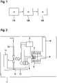
- FIG. 1 shows an exemplary and schematic sequence of a method proposed here.
- the method is used to operate a heater 2 and in particular allows a mixture composition (fuel and combustion air) to be regulated without using an ionization effect of a flame 6 of the heater 2.
- the blocks 110, 120 and 130 of steps a), b) and c) can occur in a regular procedure.
- a temperature sensor 1 is heated.
- the temperature sensor 1 can be a resistance-based temperature sensor, so that when a voltage is applied, a current flows through the temperature sensor 1, accompanied by a conversion of the electrical energy into thermal energy at the electrical resistance of the temperature sensor 1, and thus with a heating of the same.
- a heat source for example an electrical resistor through which current flows
- a heat source can also be arranged in the immediate vicinity of the temperature sensor 1 .
- a signal from the temperature sensor 1 is detected.
- the signal can be, for example, the electrical resistance of the temperature sensor 1, which can be determined and detected using the electrical voltage applied and the electrical current flowing.
- step c the heating device 2 is operated using the signal detected in block 120 (step b)).
- the heater 2 shows a schematic example of a heater 2 proposed here.
- the heater 2 can have a regulation and control device 8 that can be set up to carry out a method proposed here.
- the heater 2 (e.g. a gas condensing boiler) is equipped with a burner system arranged in a combustion chamber 9, in which gas from a gas supply duct 13 and combustion air are discharged in front of a blower, which here is an example of a conveyor device 5, via a valve 7 an air intake duct 12 in a mixture duct 11 (see mixture merging 14). This mixture is then transported by the conveyor 5 via the mixture channel 11 to the combustion chamber 9, where combustion then takes place.
- the exhaust gases produced by the combustion are routed through an internal exhaust pipe 10 to an exhaust system, not shown here.
- a temperature sensor 1 is arranged in the combustion chamber 9 in such a way that it can be positioned in or in the immediate vicinity of a flame 6 when the heater 2 is in operation.
- the temperature sensor 1 can be a resistance-based temperature sensor, which can be heated by applying an electrical voltage to carry out step a) (block 110).
- step b) (block 120)
- the signal of the temperature sensor 1 can be detected.
- step c) (block 130), it is then possible to operate the heating device 2 using the signal of the temperature sensor 1 detected in step b).
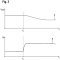
- FIG. 3 shows an example and a schematic of a parameter curve that can occur when a proposed method is implemented.
- figure 3 shows two diagrams that illustrate the advantages of a method proposed here.
- the abscissa of both diagrams represents the time t and is analogous to both diagrams.
- the upper diagram shows a temperature signal ⁇ sens 3 of a (not actively heated) temperature sensor according to the prior art arranged in the region of a flame 6 in a combustion chamber 9 of a heater 2 .
- a loss of flame 6 at time tv can be detected by a delayed reduction in detected temperature ⁇ sens .
- the diagram below shows an actuating signal 4 from a controller for the electrical output P el of an actively heated temperature sensor 1.
- the flame 6 is lost at time t V .
- the actuating signal 4 from the controller for the electrical output P el reacts immediately after the flame has been lost 6 at time tv, compared to the temperature signal ⁇ sens 3 of a (not actively heated) temperature sensor arranged in the region of a flame 6 in a combustion chamber 9 of a heater 2 .
- the significantly higher reaction speed of the actuating signal 4 of the regulator of the electrical power P el enables it to be used for regulating the heater 1, in particular for regulating the composition of the mixture of fuel and combustion air.
Landscapes
- Engineering & Computer Science (AREA)
- Chemical & Material Sciences (AREA)
- Combustion & Propulsion (AREA)
- Mechanical Engineering (AREA)
- General Engineering & Computer Science (AREA)
- Control Of Combustion (AREA)
Applications Claiming Priority (1)
| Application Number | Priority Date | Filing Date | Title |
|---|---|---|---|
| DE102021121093.3A DE102021121093A1 (de) | 2021-08-13 | 2021-08-13 | Verfahren zum Betreiben eines Heizgerätes, Computerprogramm, Speichermedium, Regel- und Steuergerät, Heizgerät und Verwendung eines Signals |
Publications (2)
| Publication Number | Publication Date |
|---|---|
| EP4137745A1 true EP4137745A1 (fr) | 2023-02-22 |
| EP4137745B1 EP4137745B1 (fr) | 2026-04-15 |
Family
ID=82846169
Family Applications (1)
| Application Number | Title | Priority Date | Filing Date |
|---|---|---|---|
| EP22188991.8A Active EP4137745B1 (fr) | 2021-08-13 | 2022-08-05 | Procédé permettant de faire fonctionner un chauffage, programme informatique, support d'enregistrement, appareil de régulation et de commande, appareil chauffant et utilisation d'un signal |
Country Status (2)
| Country | Link |
|---|---|
| EP (1) | EP4137745B1 (fr) |
| DE (1) | DE102021121093A1 (fr) |
Cited By (2)
| Publication number | Priority date | Publication date | Assignee | Title |
|---|---|---|---|---|
| EP4459183A1 (fr) * | 2023-05-03 | 2024-11-06 | Vaillant GmbH | Procédé de fonctionnement d'un appareil de chauffage, appareil de chauffage et programme informatique |
| EP4621292A1 (fr) * | 2024-03-22 | 2025-09-24 | Vaillant GmbH | Procédé de fonctionnement d'un appareil de chauffage, appareil de chauffage et programme informatique |
Citations (6)
| Publication number | Priority date | Publication date | Assignee | Title |
|---|---|---|---|---|
| DE1004270B (de) | 1954-03-12 | 1957-03-14 | Felten & Guilleaume Carlswerk | Einrichtung zur Kurztrennung von Leistungsschaltern mit zeitlich verzoegerter endgueltiger Abschaltung bei Verwendung von mechanischen Ausloeseorganen, wie Primaerrelais u. dgl. |
| US3282324A (en) * | 1965-10-11 | 1966-11-01 | Ram Domestic Products Company | Automatic fuel ignition and heat detection system |
| GB2270748A (en) | 1992-09-17 | 1994-03-23 | Caradon Heating Ltd | Burner control systems |
| DE19813313A1 (de) * | 1998-03-26 | 1999-04-15 | Bosch Gmbh Robert | Verfahren zur Regelung eines Brenners, insbesondere eines vormischenden Gasbrenners |
| WO2003052320A1 (fr) * | 2001-12-18 | 2003-06-26 | Nanogate Technologies Gmbh | Surveillance d'une flamme |
| DE102004055716C5 (de) | 2004-06-23 | 2010-02-11 | Ebm-Papst Landshut Gmbh | Verfahren zur Regelung einer Feuerungseinrichtung und Feuerungseinrichtung (Elektronischer Verbund I) |
Family Cites Families (2)
| Publication number | Priority date | Publication date | Assignee | Title |
|---|---|---|---|---|
| DE10045270C2 (de) | 2000-08-31 | 2002-11-21 | Heatec Thermotechnik Gmbh | Feuerungseinrichtung und Verfahren zum Regeln derselben |
| DE102008041026A1 (de) | 2008-08-06 | 2010-02-11 | Robert Bosch Gmbh | Verfahren zur Bestimmung der Temperatur und des Volumenstroms eines Fluids sowie Schaltungsanordnung und Motorsteuergerät |
-
2021
- 2021-08-13 DE DE102021121093.3A patent/DE102021121093A1/de active Pending
-
2022
- 2022-08-05 EP EP22188991.8A patent/EP4137745B1/fr active Active
Patent Citations (6)
| Publication number | Priority date | Publication date | Assignee | Title |
|---|---|---|---|---|
| DE1004270B (de) | 1954-03-12 | 1957-03-14 | Felten & Guilleaume Carlswerk | Einrichtung zur Kurztrennung von Leistungsschaltern mit zeitlich verzoegerter endgueltiger Abschaltung bei Verwendung von mechanischen Ausloeseorganen, wie Primaerrelais u. dgl. |
| US3282324A (en) * | 1965-10-11 | 1966-11-01 | Ram Domestic Products Company | Automatic fuel ignition and heat detection system |
| GB2270748A (en) | 1992-09-17 | 1994-03-23 | Caradon Heating Ltd | Burner control systems |
| DE19813313A1 (de) * | 1998-03-26 | 1999-04-15 | Bosch Gmbh Robert | Verfahren zur Regelung eines Brenners, insbesondere eines vormischenden Gasbrenners |
| WO2003052320A1 (fr) * | 2001-12-18 | 2003-06-26 | Nanogate Technologies Gmbh | Surveillance d'une flamme |
| DE102004055716C5 (de) | 2004-06-23 | 2010-02-11 | Ebm-Papst Landshut Gmbh | Verfahren zur Regelung einer Feuerungseinrichtung und Feuerungseinrichtung (Elektronischer Verbund I) |
Cited By (2)
| Publication number | Priority date | Publication date | Assignee | Title |
|---|---|---|---|---|
| EP4459183A1 (fr) * | 2023-05-03 | 2024-11-06 | Vaillant GmbH | Procédé de fonctionnement d'un appareil de chauffage, appareil de chauffage et programme informatique |
| EP4621292A1 (fr) * | 2024-03-22 | 2025-09-24 | Vaillant GmbH | Procédé de fonctionnement d'un appareil de chauffage, appareil de chauffage et programme informatique |
Also Published As
| Publication number | Publication date |
|---|---|
| DE102021121093A1 (de) | 2023-02-16 |
| EP4137745B1 (fr) | 2026-04-15 |
Similar Documents
| Publication | Publication Date | Title |
|---|---|---|
| DE102004055716B4 (de) | Verfahren zur Regelung einer Feuerungseinrichtung und Feuerungseinrichtung (Elektronischer Verbund I) | |
| US8721325B2 (en) | Method for starting a combustion device under unknown basic conditions | |
| EP4137745A1 (fr) | Procédé permettant de faire fonctionner un chauffage, programme informatique, support d'enregistrement, appareil de régulation et de commande, appareil chauffant et utilisation d'un signal | |
| EP1761728A1 (fr) | Procede de reglage du coefficient d'air sur un dispositif de chauffage et dispositif de chauffage | |
| EP0833106B1 (fr) | Procédé et dispositif d'optimisation du fonctionnement d'un brûleur à gaz | |
| DE69228198T2 (de) | Thermoelektrischer sensor | |
| EP3779280A1 (fr) | Appareil chauffant pour un bâtiment | |
| DE102020128611A1 (de) | Verfahren und Vorrichtung zum Zünden eines Brenners | |
| EP4279811B1 (fr) | Procédé de fonctionnement d'un appareil de chauffage, programme informatique, appareil de commande et de régulation, appareil de chauffage et utilisation d'une résistance électrique déterminée | |
| DE19734574B4 (de) | Verfahren und Vorrichtung zum Regeln eines Brenners, insbesondere eines vollvormischenden Gasbrenners | |
| DE10045272C2 (de) | Feuerungseinrichtung mit Überwachung der Flammenlänge und Verfahren zum Steuern oder Regeln dieser Einrichtung | |
| EP4339512B1 (fr) | Procédé de fonctionnement d'un appareil de chauffage, programme informatique, appareil de régulation et de commande, et appareil de chauffage pour la réalisation du procédé | |
| EP4345378B1 (fr) | Procédé de mise en service d'un appareil de chauffage, appareil de commande et de régulation, appareil de chauffage et programme informatique | |
| EP4174375B1 (fr) | Procédé de validation d'un signal d'un dispositif de surveillance de flamme d'un appareil de chauffage, programme informatique, support de stockage, appareil de commande et utilisation d'un capteur de température | |
| US3645511A (en) | Pilot for gas burner | |
| EP4414604B1 (fr) | Procédé de fonctionnement d'un appareil de chauffage fonctionnant à l'hydrogène, appareil de chauffage et logiciel | |
| EP4174376A1 (fr) | Procédé de fonctionnement d'un appareil de chauffage, programme informatique, support d'enregistrement, appareil de commande, appareil de chauffage et utilisation d'un courant d'ionisation détecté et d'une température détectée | |
| EP4459183B1 (fr) | Procédé de fonctionnement d'un appareil de chauffage, appareil de chauffage et programme informatique | |
| EP4462021B1 (fr) | Procédé de fonctionnement d'un appareil de chauffage, programme informatique, appareil de réglage et de commande et appareil de chauffage | |
| DE102022123091A1 (de) | Verfahren zum Betreiben eines Heizgerätes, Computerprogramm, Regel- und Steuergerät und Heizgerät | |
| EP4556795A1 (fr) | Procédé de fonctionnement d'un appareil de chauffage, programme informatique, appareil de régulation et de commande, et appareil de chauffage | |
| EP4421386B1 (fr) | Procédé de fonctionnement d'un appareil de chauffage, programme informatique, appareil de régulation et de commande et appareil de chauffage | |
| EP4174377A1 (fr) | Procédé de fonctionnement d'un appareil de chauffage, programme informatique, support d'enregistrement, appareil de régulation et de commande, appareil de chauffage et utilisation d'un signal | |
| DE202004017851U1 (de) | Feuerungseinrichtung | |
| EP4357671A1 (fr) | Procédé de mise en service d'un appareil de chauffage, programme informatique, appareil de commande et de régulation et appareil de chauffage |
Legal Events
| Date | Code | Title | Description |
|---|---|---|---|
| PUAI | Public reference made under article 153(3) epc to a published international application that has entered the european phase |
Free format text: ORIGINAL CODE: 0009012 |
|
| STAA | Information on the status of an ep patent application or granted ep patent |
Free format text: STATUS: THE APPLICATION HAS BEEN PUBLISHED |
|
| AK | Designated contracting states |
Kind code of ref document: A1 Designated state(s): AL AT BE BG CH CY CZ DE DK EE ES FI FR GB GR HR HU IE IS IT LI LT LU LV MC MK MT NL NO PL PT RO RS SE SI SK SM TR |
|
| STAA | Information on the status of an ep patent application or granted ep patent |
Free format text: STATUS: REQUEST FOR EXAMINATION WAS MADE |
|
| 17P | Request for examination filed |
Effective date: 20230817 |
|
| RBV | Designated contracting states (corrected) |
Designated state(s): AL AT BE BG CH CY CZ DE DK EE ES FI FR GB GR HR HU IE IS IT LI LT LU LV MC MK MT NL NO PL PT RO RS SE SI SK SM TR |
|
| STAA | Information on the status of an ep patent application or granted ep patent |
Free format text: STATUS: EXAMINATION IS IN PROGRESS |
|
| 17Q | First examination report despatched |
Effective date: 20240814 |
|
| GRAP | Despatch of communication of intention to grant a patent |
Free format text: ORIGINAL CODE: EPIDOSNIGR1 |
|
| STAA | Information on the status of an ep patent application or granted ep patent |
Free format text: STATUS: GRANT OF PATENT IS INTENDED |
|
| RIC1 | Information provided on ipc code assigned before grant |
Ipc: F23D 14/02 20060101AFI20251031BHEP Ipc: F23Q 7/10 20060101ALI20251031BHEP Ipc: F23N 5/24 20060101ALI20251031BHEP Ipc: F23N 5/14 20060101ALI20251031BHEP Ipc: F23N 1/02 20060101ALI20251031BHEP Ipc: F24C 3/10 20060101ALI20251031BHEP |
|
| INTG | Intention to grant announced |
Effective date: 20251118 |
|
| GRAS | Grant fee paid |
Free format text: ORIGINAL CODE: EPIDOSNIGR3 |
|
| GRAA | (expected) grant |
Free format text: ORIGINAL CODE: 0009210 |
|
| STAA | Information on the status of an ep patent application or granted ep patent |
Free format text: STATUS: THE PATENT HAS BEEN GRANTED |
|
| AK | Designated contracting states |
Kind code of ref document: B1 Designated state(s): AL AT BE BG CH CY CZ DE DK EE ES FI FR GB GR HR HU IE IS IT LI LT LU LV MC MK MT NL NO PL PT RO RS SE SI SK SM TR |
|
| REG | Reference to a national code |
Ref country code: CH Ref legal event code: F10 Free format text: ST27 STATUS EVENT CODE: U-0-0-F10-F00 (AS PROVIDED BY THE NATIONAL OFFICE) Effective date: 20260415 |