EP4137749A1 - Appareil de cuisson doté d'un système doté d'un récipient de liquide - Google Patents
Appareil de cuisson doté d'un système doté d'un récipient de liquide Download PDFInfo
- Publication number
- EP4137749A1 EP4137749A1 EP22188287.1A EP22188287A EP4137749A1 EP 4137749 A1 EP4137749 A1 EP 4137749A1 EP 22188287 A EP22188287 A EP 22188287A EP 4137749 A1 EP4137749 A1 EP 4137749A1
- Authority
- EP
- European Patent Office
- Prior art keywords
- liquid container
- connection
- opening
- cooking appliance
- connecting channel
- Prior art date
- Legal status (The legal status is an assumption and is not a legal conclusion. Google has not performed a legal analysis and makes no representation as to the accuracy of the status listed.)
- Withdrawn
Links
Images


Classifications
-
- F—MECHANICAL ENGINEERING; LIGHTING; HEATING; WEAPONS; BLASTING
- F24—HEATING; RANGES; VENTILATING
- F24C—DOMESTIC STOVES OR RANGES ; DETAILS OF DOMESTIC STOVES OR RANGES, OF GENERAL APPLICATION
- F24C15/00—Details
- F24C15/32—Arrangements of ducts for hot gases, e.g. in or around baking ovens
- F24C15/322—Arrangements of ducts for hot gases, e.g. in or around baking ovens with forced circulation
- F24C15/327—Arrangements of ducts for hot gases, e.g. in or around baking ovens with forced circulation with air moisturising
Definitions
- the invention relates to a cooking appliance with a system with a liquid container for the cooking appliance according to the preamble of patent claim 1.
- a household appliance with a control panel and with a liquid container designed as a tank for receiving a fluid is known.
- the tank In the operating position of the household appliance, the tank is arranged behind the control panel in the interior of the household appliance, the control panel being movable back and forth between a rest position without access to the tank and an exposed position with access to the tank.
- the tank has a connecting channel designed as an outlet valve, with the liquid container having a combined filling/emptying opening for filling and/or emptying the liquid container and a connection opening arranged below the filling/emptying opening for flow-conducting connection to the cooking appliance designed as a household appliance and on the other hand, the connecting channel has a connecting piece for the flow-conducting connection of the connecting channel with the connection opening and a dip connecting piece with a dip connecting-piece opening arranged below the connecting opening for the flow-conducting connection of the connecting channel with the liquid container.
- the invention therefore addresses the problem of improving a cooking appliance with a system having a liquid container for the cooking appliance.
- a cooking appliance with the features of patent claim 1, which is characterized in that the connecting channel additionally has a return opening arranged above the immersion nozzle opening for the flow-conducting connection of the connecting channel to the liquid container, the connecting channel being designed in such a way that an in the liquid rising from the dip fitting flows back through the return opening into the liquid container until the return opening is closed by liquid in the liquid container.
- the advantage that can be achieved with the invention is, in particular, that a system with a liquid container for a cooking appliance, a connecting channel and a cooking appliance are improved. Due to the inventive design of the system with a liquid container for a cooking appliance, the connecting channel for a system and the cooking appliance, it is possible, for example, to move the liquid container filled with a liquid more easily by means of the connecting channel from the cooking appliance to a drain for emptying the liquid stored in the liquid container To wear, for example, a condensate, without there being a risk that the liquid in an undesired manner from the connection opening of the liquid container out and runs down on or in the cooking appliance or drips onto a floor of a kitchen or the like.
- the system according to the invention can be freely selected in terms of type, mode of operation, material and dimensioning within wide, suitable limits. See, for example, the above statements, in which the system is used on the one hand for collecting and disposing of condensate from the cooking appliance and on the other hand for supplying the cooking chamber of the cooking appliance with water or the like. It is also conceivable that the system according to the invention can be used both for supplying the cooking appliance with liquid and for disposing of liquid from the cooking appliance. As already stated, the liquid can be water or any other suitable liquid. Purely as an example, only cleaning fluids or the like are referred to here.
- the system additionally has a fill level monitor for monitoring a maximum fill level in the liquid container in the connection position of the liquid container, the maximum fill level being arranged between the return flow opening and the dip nozzle opening. In this way it is possible to automatically monitor the maximum filling level in the liquid container for the proper functioning of the system. If the maximum fill level is exceeded, suitable actions can be triggered, for example an acoustic and/or visual warning to a user of the cooking appliance or the liquid being automatically pumped out of the liquid container.
- a further advantageous development of the system according to the invention provides that the filling/emptying opening is arranged on an upper side of the liquid container, preferably that the filling/emptying opening extends over a large part of the upper side of the liquid container, particularly preferably that the filling/emptying Drainage opening can be covered by a lid of the liquid container or is arranged in a lid of the liquid container. This enables easy handling of the liquid container when it is being filled with liquid or when it is being emptied. This applies in particular to the preferred and in particular to the particularly preferred embodiment of this development.
- the connecting channel is designed as a separate component that can be connected to the liquid container, the connecting channel being fixed in a flow-conducting manner in a mounting position of the connecting channel at the connection opening of the liquid container.
- the production of the connection channel is made possible independently of the production of the liquid container. Accordingly, there is greater design freedom in the production of the liquid container and the connecting channel.
- the liquid container on the one hand and the connecting channel on the other hand can be made of different materials, so that the choice of material can be better adapted to the functional requirements in each case.
- connection channel when the system is transferred into its connection position, the connection channel can be connected to a device connection piece of the cooking appliance that protrudes through the connection opening into the liquid container in the connection position for the flow-conducting connection of the liquid container to the cooking appliance, preferably that the connecting channel has at least one circumferential sealing lip on the device socket side, particularly preferably that the sealing lip engages in a groove of the device socket designed to correspond to the sealing lip in the connection position of the system.
- the at least one circumferential sealing lip also ensures that liquid adhering to the device connector when the system is transferred from its connection position to a non-connection position, i.e. to a position in which the system is no longer connected to the device connector in a flow-conducting manner, is not applied in an uncontrolled manner or runs down in the cooking appliance, but is stripped off by means of the sealing lip in such a way that the liquid can drain back into the liquid container.
- the device connector it is also possible for the device connector to have a drip flange on an outlet opening of the device connector on the connecting channel side.
- connection channel has at least one circumferential sealing lip on the connection piece side for sealing an appliance connection piece of the cooking appliance protruding through the connection opening into the liquid container in the connected position of the system.
- connection channel is designed as a one-piece silicone part, preferably as a silicone elastomer part or silicone rubber part. Silicone is particularly advantageous for the function of the connection channel according to the invention. This applies in particular to the design of the connecting channel as a silicone elastomer part or as a silicone rubber part.
- connection channel according to the invention provides that the connecting piece is designed for a positive connection, preferably for a locking connection, with an edge of the connection opening of the liquid container. In this way, the transfer of the connection channel according to the invention into its mounting position is made possible in a manner that is particularly simple in terms of design and production technology.
- connection channel has a spacer rib on the connection piece side for holding the connection channel at a predetermined distance from a wall of the liquid container having the connection opening. This makes it possible in a simple manner to set a distance of the connecting duct from the wall on which the connection opening is formed, which is required for the proper functioning of the connecting duct, when transferring the connecting duct into its installation position.
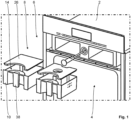
- the cooking appliance 2 is embodied as a steam cooker for the household sector and comprises a cooking chamber 4 for preparing the food to be cooked (not shown) and a liquid unit 6 for introducing a liquid (not shown), namely water, into and ejecting a liquid, namely condensate, from the Cooking chamber 4, wherein the liquid unit 6 comprises a system 8 with a liquid container 10 for the cooking device 2 for receiving a liquid, namely the condensate of the cooking device 2, and a connecting channel 12 for the flow-conducting connection of the liquid container 10 to the cooking device 2 in a 2 shown connection position of the system 8, in which the liquid container 10 is connected in a flow-conducting manner to the cooking appliance 2 by means of the connecting channel 12, and wherein on the one hand the liquid container 10 has a combined filling/emptying opening 14 for emptying the liquid container and one below the filling/emptying Drainage opening 14 arranged connection opening 16 for the flow-conducting connection to the cooking appliance 2 and on the other hand the connecting channel 12 has a
- the connecting channel 12 additionally has a return flow opening 24 for the flow-conducting connection of the connecting channel 12 to the liquid container 10, the connecting channel 12 being designed in such a way that a liquid rising in the dip fitting 20 is blocked by a liquid located in the liquid container 10 until the return flow opening 24 is closed Liquid flows back into the liquid container 10 through the return opening 24 .
- the combined filling/emptying opening 14 of the liquid container 10 is arranged on an upper side of the liquid container 10, with the filling/emptying opening 14 having a Most of the top of the liquid container 10 extends. How from the 1 As can be seen, the filling/emptying opening 14 can be covered by a cover 26 of the liquid container 10 . However, it is also conceivable that the combined filling/draining opening is arranged in a cover of the liquid container. See, for example, the one in the image plane 1 right next to the liquid container 10 shown liquid container with lid, which is designed in the present embodiment to supply the cooking appliance 2 with fresh water. In other embodiments of the invention, the last-mentioned liquid container can also be designed as a component of a system according to the invention as an alternative or in addition to the system 8 .
- the connecting channel 12 is formed here as a connectable to the liquid container 10 separate component, wherein the connecting channel 12 in a 2 and 3 illustrated assembly position of the connecting channel 12 is fixed in a flow-conducting manner at the connection opening 16 of the liquid container 10 .
- the connecting channel 12 thus has the connecting piece 18 for the flow-conducting connection of the connecting channel 12 with the connecting opening 16 and the dip connecting piece 20 with a dip connecting piece opening 22 arranged below the connecting opening 16 for the flow-conducting connection of the connecting channel 12 with the liquid container 10, the connecting channel 12 also having the return flow opening 24 for the flow-conducting connection of the connecting channel 12 to the liquid container 10, and wherein the connecting channel 12 is designed in such a way that the liquid rising in the dip fitting 20 flows through the return opening 24 into the Liquid container 10 flows back.
- the connecting channel 12 is designed as a one-piece silicone part, namely a silicone rubber part.
- the liquid container 10 and a receptacle of the cooking appliance 2 for the liquid container 10 in the connection position of the system 8 are each made of a hard plastic.
- connection channel 12 located in its mounting position is in the transfer of the system 8 in the 2
- the connection position shown can be connected to a device socket 28 of the cooking appliance 2 that protrudes through the connection opening 16 into the liquid container 10 in the connection position for the flow-conducting connection of the liquid container 10 to the cooking appliance 2, with the connection channel 12 having a circumferential sealing lip 30 on the device socket side, namely in such a way that the sealing lip 30 engages in the connection position of the system 8 in a groove 32 of the device socket 28 which is designed to correspond to the sealing lip 30 . See the 2 and 3 in a synopsis.
- the device socket 28 in which present embodiment of the cooking device according to the invention at a connecting channel side outlet opening of the device socket 28 a drip flange 33 on.
- the connecting piece 18 of the connecting channel 12 is designed for a positive connection, namely for a locking connection, with an edge 34 of the connection opening 16 of the liquid container 10 . So that the spacing of the connecting channel 12 from a wall of the liquid container 10 that has the connection opening 16, which is required for the proper functioning of the connecting channel 12, can be easily produced in terms of design and production technology, the connecting channel 12 has a spacer rib 36 on the connecting piece side for holding the connecting channel 12 at a predetermined distance the aforesaid wall of the liquid container 10. Accordingly, from the 2 and 3 visible wall thickness of the connecting channel 12 in the image planes of 2 and 3 in the area of the immersion socket 20 on the right side in each case about twice as thick as on the left side in each case.
- connection channel 12 In order to produce the system 8, it is only necessary for a fitter (not shown) to connect the connecting channel 12 to the liquid container 10 in such a way that the connecting channel 12 is flow-conducting with its dip nozzle opening 22 formed on the dip nozzle 20 and its return flow opening 24 arranged above the dip nozzle opening 22 with the liquid container 10 and on the other hand with its connecting piece 18 is connected in a flow-conducting manner to the connection opening 16 of the liquid container 10 .
- the fitter inserts the connection channel 12 with its connection piece 18 into the connection opening 16 of the liquid container 10 in such a way that the connection channel 12 is positively connected by means of its connection piece 18, namely in a snap-in manner, to the edge 34 delimiting the connection opening 16.
- the spacer rib 36 of the connecting channel 12 formed in the area of the immersion fitting 20 on the connecting piece side ensures the correct spacing of the connecting channel 12 from the wall of the liquid container 10 having the connection opening 16.
- the connecting channel 12 is then located in its in the 2 and 3 mounting position shown. The System 8 is now operational.
- the system is 8 in which in the 2 connection position shown, in which the connection channel 12 located in the mounting position the Liquid container 10 fluidly connected to the cooking appliance 2, namely the device nozzle 28 of the cooking appliance 2.
- the appliance connection piece 28 is fixed, that is to say immovable, on a receptacle of the cooking appliance 2 for the system 8 in its connection position. See the 2 and 3 .
- the fresh water from the aforementioned liquid container is supplied to the cooking chamber 4 of the cooking appliance 2 by means of the liquid unit 6, for example for Preparation of the food to be cooked, not shown, supplied in liquid form or in vapor form.
- condensate is formed, which must be discharged from the cooking chamber 4 by means of the liquid unit 6 at a predetermined program point in the program sequence of the automatic program.
- the condensate which is not shown, is not fed back into the aforementioned liquid container for the fresh water, but rather into the liquid container 10 by means of the liquid unit 6 .
- the condensate is introduced in a manner known per se to a person skilled in the art by means of the liquid unit 6 through the appliance socket 28 and its outlet opening from the cooking appliance 2 into the connecting channel 12 of the system 8 .
- the drip flange 33 ensures that there is as little condensate as possible adhering to the device socket 28.
- the condensate finally reaches the liquid container 10 through the dip socket 20 and its dip socket opening 22 of the device socket 28 engages, ensures a very good seal of the aforementioned flow-conducting connection to the free environment.
- a user of the cooking appliance 2 (not shown) has to empty the liquid container 10.
- the maximum fill level is located between the return flow opening 24 and the dip nozzle opening 22 .
- Such an emptying of the liquid container 10 can be provided, for example, after each use of the cooking appliance 2 . In this case it is not absolutely necessary for the system 2 to have an automatic filling level monitor.
- the system according to the invention in other embodiments of the invention additionally has a fill level monitor for monitoring the maximum fill level in the liquid container in the connection position of the liquid container, with the maximum fill level being arranged between the return flow opening and the dip nozzle opening.
- the user of the cooking appliance then receives an automatic message indicating that he must empty the liquid container.
- the user In order to empty the liquid container 10, the user removes the system 8 from the cooking appliance 2; the user transfers the system 8 from its in the 2 connection position shown in its in the 1 and 3 shown non-connection position.
- the user grasps the liquid container 10, for example by a handle 38 provided specifically for this purpose, and pulls the liquid container 10 with the connecting channel 12 mounted thereon out of the cooking appliance 2.
- the flow-conducting connection between the device connection piece 28 and the connecting channel 12 is released and, on the other hand, the circumferential sealing lip 30 wipes off any condensate adhering to the device connection piece 28 from the device connection piece 28 in such a way that this condensate runs off into the liquid container 10 by means of the sealing lip 30 can.
- the user can carry the system 8 to empty the condensate from the liquid container 10, for example to a drain (not shown).
- a drain (not shown). Due to the inventive design of the system 8 and the connecting channel 12, it is possible, for example, to move the liquid container 10 filled with a liquid more easily by means of the connecting channel 12 from the cooking appliance 2 to the drain for emptying the liquid stored in the liquid container 10, namely the condensate wear without the risk that the liquid in an undesired manner from the connection opening 16 of the liquid container 10 out and runs down on or in the cooking appliance 2 or drips onto a floor of a kitchen or the like.
- the liquid container 10 with the connecting channel 12 can be reinserted into the cooking appliance 2, ie the system 8 can be transferred from its non-connected position to its connected position.
- the liquid container 10 by means of the connecting piece 18 of the connecting channel 12, as can be seen from a synopsis of the 2 and 3 shown, pushed onto the device socket 28 of the cooking appliance 2.
- the invention is not limited to the present embodiment.
- the invention can also be used advantageously with other cooking appliances.
- use of the invention is not limited to household appliances. Accordingly, the invention can also be advantageously used in commercial devices, ie cooking devices for professional use.
Landscapes
- Engineering & Computer Science (AREA)
- Chemical & Material Sciences (AREA)
- Combustion & Propulsion (AREA)
- Mechanical Engineering (AREA)
- General Engineering & Computer Science (AREA)
- Cookers (AREA)
Applications Claiming Priority (1)
| Application Number | Priority Date | Filing Date | Title |
|---|---|---|---|
| BE20215652A BE1029687B1 (de) | 2021-08-16 | 2021-08-16 | System mit einem Flüssigkeitsbehälter für ein Gargerät, Verbindungskanal für ein System und Gargerät mit einem System |
Publications (1)
| Publication Number | Publication Date |
|---|---|
| EP4137749A1 true EP4137749A1 (fr) | 2023-02-22 |
Family
ID=77431079
Family Applications (1)
| Application Number | Title | Priority Date | Filing Date |
|---|---|---|---|
| EP22188287.1A Withdrawn EP4137749A1 (fr) | 2021-08-16 | 2022-08-02 | Appareil de cuisson doté d'un système doté d'un récipient de liquide |
Country Status (2)
| Country | Link |
|---|---|
| EP (1) | EP4137749A1 (fr) |
| BE (1) | BE1029687B1 (fr) |
Citations (4)
| Publication number | Priority date | Publication date | Assignee | Title |
|---|---|---|---|---|
| EP1378704A1 (fr) * | 2002-07-05 | 2004-01-07 | KE-KELIT Kunststoffwerk Gesellschaft m.b.H. | Pièce en matière plastique pour coupler aux moins deux tuyaux |
| US7326891B2 (en) * | 2005-06-08 | 2008-02-05 | Samsung Electronics Co., Ltd. | Steam generation apparatus using induction heating and oven including the same |
| DE102007048200A1 (de) | 2007-10-08 | 2009-04-09 | Miele & Cie. Kg | Haushaltsgerät mit einer Bedienblende und mit einem Tank zur Aufnahme eines Fluids |
| EP3309462A1 (fr) * | 2016-10-12 | 2018-04-18 | Miele & Cie. KG | Égouttoir pour un appareil ménager et appareil ménager doté d'un égouttoir |
-
2021
- 2021-08-16 BE BE20215652A patent/BE1029687B1/de not_active IP Right Cessation
-
2022
- 2022-08-02 EP EP22188287.1A patent/EP4137749A1/fr not_active Withdrawn
Patent Citations (4)
| Publication number | Priority date | Publication date | Assignee | Title |
|---|---|---|---|---|
| EP1378704A1 (fr) * | 2002-07-05 | 2004-01-07 | KE-KELIT Kunststoffwerk Gesellschaft m.b.H. | Pièce en matière plastique pour coupler aux moins deux tuyaux |
| US7326891B2 (en) * | 2005-06-08 | 2008-02-05 | Samsung Electronics Co., Ltd. | Steam generation apparatus using induction heating and oven including the same |
| DE102007048200A1 (de) | 2007-10-08 | 2009-04-09 | Miele & Cie. Kg | Haushaltsgerät mit einer Bedienblende und mit einem Tank zur Aufnahme eines Fluids |
| EP3309462A1 (fr) * | 2016-10-12 | 2018-04-18 | Miele & Cie. KG | Égouttoir pour un appareil ménager et appareil ménager doté d'un égouttoir |
Also Published As
| Publication number | Publication date |
|---|---|
| BE1029687A1 (de) | 2023-03-10 |
| BE1029687B1 (de) | 2023-03-13 |
Similar Documents
| Publication | Publication Date | Title |
|---|---|---|
| DE112015006456B4 (de) | Vorrichtung zum Erzeugen von Milchschaum | |
| DE102010049974C5 (de) | Filtervorrichtung | |
| EP3064667B1 (fr) | Joint d'etancheite d'un dispositif d'ecoulement | |
| EP2010837A2 (fr) | Appareil frigorifique comportant un système d'écoulement de condensat | |
| EP3748094B1 (fr) | Wc douche avec dispositif de sécurité contre l'aspiration d'eau sale dans le tuyau d'eau potable | |
| EP3673211A1 (fr) | Appareil de cuisson à la vapeur | |
| EP3309462B1 (fr) | Appareil ménager | |
| BE1029687B1 (de) | System mit einem Flüssigkeitsbehälter für ein Gargerät, Verbindungskanal für ein System und Gargerät mit einem System | |
| EP1792000B1 (fr) | Dispositif d'aeration d'une conduite d'ecoulement d'un appareil menager conduisant de l'eau | |
| WO2008107177A1 (fr) | Raccord pour tuyaux conçu pour l'évacuation de matières fécales sur des véhicules sur rails | |
| DE102017124921A1 (de) | Auffangschale für Flüssigkeitsreste und Getränkeautomat mit einer derartigen Auffangschale | |
| EP0433641B1 (fr) | Dispositif de commande de l'écoulement de fluide vers un réservoir | |
| BE1030966B1 (de) | Gargerät, vorzugsweise mit Selbstreinigungsfunktion und bzw. oder mit Dampfunktion, besonders vorzugsweise Backofen-Dampfgarer-Kombigerät, vorzugsweise mit Selbstreinigungsfunktion | |
| EP1861536B1 (fr) | Dispositif de distribution de detergent | |
| EP3657020B1 (fr) | Dispositif d'évacuation pour une conduite d'aspiration | |
| EP2648974A1 (fr) | Dispositif de purge d'eau fraîche exempte de contamination dans un avion | |
| AT400598B (de) | Kunststoffabzweiger für kanäle | |
| EP3202291B1 (fr) | Appareil de cuisson et dispositif d'écoulement associé | |
| DE102017214930A1 (de) | Dampfgargerät | |
| DE69904252T2 (de) | Autoklaven | |
| EP3673209B1 (fr) | Appareil de cuisson à vapeur | |
| CH701794A1 (de) | Grossküchenvorrichtung. | |
| DE202016000739U1 (de) | Gargeräteabfluss mit rotierendem Abflussstöpsel | |
| DE1610315A1 (de) | Weitgehend selbsttaetige und dampfdichte elektrische Waschmaschine | |
| DE202025105117U1 (de) | Vorrichtung zum geruchsdichten Verschließen einer Abflussleitung eines wasserlosen Urinals |
Legal Events
| Date | Code | Title | Description |
|---|---|---|---|
| PUAI | Public reference made under article 153(3) epc to a published international application that has entered the european phase |
Free format text: ORIGINAL CODE: 0009012 |
|
| STAA | Information on the status of an ep patent application or granted ep patent |
Free format text: STATUS: THE APPLICATION HAS BEEN PUBLISHED |
|
| AK | Designated contracting states |
Kind code of ref document: A1 Designated state(s): AL AT BE BG CH CY CZ DE DK EE ES FI FR GB GR HR HU IE IS IT LI LT LU LV MC MK MT NL NO PL PT RO RS SE SI SK SM TR |
|
| STAA | Information on the status of an ep patent application or granted ep patent |
Free format text: STATUS: THE APPLICATION IS DEEMED TO BE WITHDRAWN |
|
| 18D | Application deemed to be withdrawn |
Effective date: 20230823 |