EP4137787A1 - Procédé de détection d'inclinaison et dispositif correspondant - Google Patents
Procédé de détection d'inclinaison et dispositif correspondant Download PDFInfo
- Publication number
- EP4137787A1 EP4137787A1 EP20930978.0A EP20930978A EP4137787A1 EP 4137787 A1 EP4137787 A1 EP 4137787A1 EP 20930978 A EP20930978 A EP 20930978A EP 4137787 A1 EP4137787 A1 EP 4137787A1
- Authority
- EP
- European Patent Office
- Prior art keywords
- weight
- inclination
- inclination angle
- built
- value
- Prior art date
- Legal status (The legal status is an assumption and is not a legal conclusion. Google has not performed a legal analysis and makes no representation as to the accuracy of the status listed.)
- Withdrawn
Links
Images



Classifications
-
- G—PHYSICS
- G01—MEASURING; TESTING
- G01G—WEIGHING
- G01G19/00—Weighing apparatus or methods adapted for special purposes not provided for in the preceding groups
- G01G19/52—Weighing apparatus combined with other objects, e.g. furniture
-
- G—PHYSICS
- G01—MEASURING; TESTING
- G01B—MEASURING LENGTH, THICKNESS OR SIMILAR LINEAR DIMENSIONS; MEASURING ANGLES; MEASURING AREAS; MEASURING IRREGULARITIES OF SURFACES OR CONTOURS
- G01B7/00—Measuring arrangements characterised by the use of electric or magnetic techniques
- G01B7/30—Measuring arrangements characterised by the use of electric or magnetic techniques for measuring angles or tapers; for testing the alignment of axes
-
- G—PHYSICS
- G01—MEASURING; TESTING
- G01C—MEASURING DISTANCES, LEVELS OR BEARINGS; SURVEYING; NAVIGATION; GYROSCOPIC INSTRUMENTS; PHOTOGRAMMETRY OR VIDEOGRAMMETRY
- G01C9/00—Measuring inclination, e.g. by clinometers, by levels
- G01C9/02—Details
-
- G—PHYSICS
- G01—MEASURING; TESTING
- G01G—WEIGHING
- G01G23/00—Auxiliary devices for weighing apparatus
- G01G23/002—Means for correcting for obliquity of mounting
-
- G—PHYSICS
- G01—MEASURING; TESTING
- G01G—WEIGHING
- G01G23/00—Auxiliary devices for weighing apparatus
- G01G23/01—Testing or calibrating of weighing apparatus
-
- G—PHYSICS
- G01—MEASURING; TESTING
- G01G—WEIGHING
- G01G23/00—Auxiliary devices for weighing apparatus
- G01G23/01—Testing or calibrating of weighing apparatus
- G01G23/012—Testing or calibrating of weighing apparatus with load cells comprising in-build calibration weights
-
- G—PHYSICS
- G01—MEASURING; TESTING
- G01G—WEIGHING
- G01G23/00—Auxiliary devices for weighing apparatus
- G01G23/06—Means for damping oscillations, e.g. of weigh beams
- G01G23/10—Means for damping oscillations, e.g. of weigh beams by electric or magnetic means
-
- G—PHYSICS
- G01—MEASURING; TESTING
- G01G—WEIGHING
- G01G23/00—Auxiliary devices for weighing apparatus
- G01G23/14—Devices for determining tare weight or for cancelling out the tare by zeroising, e.g. mechanically operated
-
- G—PHYSICS
- G01—MEASURING; TESTING
- G01G—WEIGHING
- G01G23/00—Auxiliary devices for weighing apparatus
- G01G23/18—Indicating devices, e.g. for remote indication; Recording devices; Scales, e.g. graduated
- G01G23/38—Recording and/or coding devices specially adapted for weighing apparatus
- G01G23/42—Recording and/or coding devices specially adapted for weighing apparatus electrically operated
-
- G—PHYSICS
- G01—MEASURING; TESTING
- G01G—WEIGHING
- G01G23/00—Auxiliary devices for weighing apparatus
- G01G23/48—Temperature-compensating arrangements
-
- G—PHYSICS
- G06—COMPUTING OR CALCULATING; COUNTING
- G06F—ELECTRIC DIGITAL DATA PROCESSING
- G06F7/00—Methods or arrangements for processing data by operating upon the order or content of the data handled
- G06F7/02—Comparing digital values
- G06F7/026—Magnitude comparison, i.e. determining the relative order of operands based on their numerical value, e.g. window comparator
-
- G—PHYSICS
- G08—SIGNALLING
- G08B—SIGNALLING SYSTEMS, e.g. PERSONAL CALLING SYSTEMS; ORDER TELEGRAPHS; ALARM SYSTEMS
- G08B21/00—Alarms responsive to a single specified undesired or abnormal condition and not otherwise provided for
- G08B21/18—Status alarms
- G08B21/182—Level alarms, e.g. alarms responsive to variables exceeding a threshold
Definitions
- the present invention relates to a method for detecting an inclination of a weighing apparatus, and a weighing apparatus for the same.
- Patent Literature 1 For correct weighing by a weighing apparatus such as a balance, the apparatus needs to be installed horizontally.
- a method for detecting an inclination of a weighing apparatus bubble levels have been used in many cases, and in recent years, a weighing apparatus that detects an inclination by reading a bubble position by an optical sensor (Patent Literature 1) is available.
- a weighing apparatus that detects an inclination by respectively disposing weight sensors on four legs of the apparatus and comparing measurement data of the four weight sensors with respective reference data is also available (Patent Literature 2).
- Patent Literature 1 For inclination detection, in Patent Literature 1, an optical sensor needs to be added, and in Patent Literature 2, weight sensors need to be added at four positions . This poses a problem in which the number of components increases, and the apparatus configuration becomes complicated.
- An object of the present invention is, to solve the problem described above, to provide a method for automatically detecting an inclination of a weighing apparatus by the apparatus itself without an increase in the number of components, and a weighing apparatus for the same.
- a weighing apparatus includes a weight sensor, a built-in weight to be loaded on the weight sensor, an adding/removing unit for adding/removing the built-in weight, a memory storing a theoretical value of the built-in weight, and an arithmetic processing unit, wherein the arithmetic processing unit includes an inclination angle computing unit configured to obtain an apparatus inclination angle from an arc-cosine of a weighing value of the built-in weight and the theoretical value of the built-in weight.
- the arithmetic processing unit further includes an inclination angle determining unit configured to compare the apparatus inclination angle with an allowable inclination threshold, and a warning unit configured to issue a warning to prompt leveling when the inclination angle determining unit determines that there is a problem.
- the weighing apparatus further includes a temperature sensor, and a specification value of sensitivity drift caused by a temperature change and a temperature measurement value of the temperature sensor are stored in the memory
- the arithmetic processing unit includes a sensitivity drift computing unit configured to compute a sensitivity drift value by multiplying the theoretical value of the built-in weight by the specification value of the sensitivity drift and a difference between a current temperature measurement value of the temperature sensor and a temperature measurement value acquired at the time of execution of a previous calibration, and the inclination angle computing unit obtains the apparatus inclination angle after subtracting the sensitivity drift value from the theoretical value of the built-in weight.
- the arithmetic processing unit further includes an inclination angle determining unit configured to compare the apparatus inclination angle with an allowable inclination threshold, a sensitivity drift determining unit configured to compare the sensitivity drift value with an allowable drift threshold when the inclination angle determining unit determines that there is a problem, and a warning unit configured to issue a warning to prompt leveling when the inclination angle determining unit determines that there is a problem, and issue a warning to prompt a calibration when the sensitivity drift determining unit determines that there is a problem.
- an inclination abnormality threshold for suspecting a change in gravitational acceleration is further stored in the memory, and the arithmetic processing unit includes an inclination angle additional determining unit configured to compare the apparatus inclination angle with the inclination abnormality threshold, and the warning unit issues a warning to prompt a calibration for correcting a change in gravitational acceleration when the inclination angle additional determining unit determines that there is a problem.
- an inclination detecting method includes a step (A) of adding/removing a built-in weight to/from a weight sensor, a step (B) of calculating a weighing value of the built-in weight, and a step (C) of obtaining an apparatus inclination angle from an arc-cosine of the weighing value of the built-in weight and a theoretical value of the built-in weight.
- the inclination detecting method further includes a step (D) of issuing a warning to prompt leveling when the apparatus inclination angle exceeds an allowable inclination threshold.
- the inclination detecting method includes, before the step (C), a step (E) of computing a sensitivity drift value by multiplying the theoretical value of the built-in weight by a specification value of the sensitivity drift and a difference between a current temperature measurement value of the temperature sensor and a temperature measurement value acquired at the time of execution of a previous calibration, and in the step (C), the apparatus inclination angle is obtained after subtracting the sensitivity drift value from the theoretical value of the built-in weight.
- the inclination detecting method further includes a step (F) of issuing a warning to prompt a calibration when the sensitivity drift value in the step (E) exceeds an allowable drift threshold.
- the inclination detecting method further includes, after the step (C), a step (G) of prompting a calibration for correcting a change in gravitational acceleration when the apparatus inclination angle exceeds an inclination abnormality threshold for suspecting a change in gravitational acceleration.
- a weighing apparatus itself can automatically detect an inclination of the apparatus while preventing an increase in the number of components.
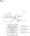
- Fig. 1 is a configuration block diagram of a weighing apparatus according to a first embodiment.
- the weighing apparatus (hereinafter, referred to as balance 10) is an electronic balance.
- the balance 10 includes a weighing pan 11, a weight sensor 12, an arithmetic processing unit 13, a memory 14, key switches 15, a display unit 16, a built-in weight 17, and an adding/removing unit 18.
- an electromagnetic balancing type, a strain gauge type, a capacitance type, or the like is used as the weight sensor 12.
- a load of a weighing object placed on the weighing pan 11 is transmitted through a beam (not illustrated) .
- the load detected by the weight sensor 12 is analog-output as weighing data, A/D converted, and output to the arithmetic processing unit 13.
- the built-in weight 17 is commonly used in balances with an automatic calibration function.
- the built-in weight 17 is loaded/unloaded by the adding/removing unit 18.
- the adding/removing unit 18 includes a built-in weight receiver portion 181, a cam 182, a motor 183, and a motor drive circuit 184.
- the built-in weight receiver portion 181 is linked to the beam connected to the weight sensor 12, and a load of the built-in weight 17 loaded on the built-in weight receiver portion 181 is transmitted to the weight sensor 12.
- the motor drive circuit 184 is connected to the arithmetic processing unit 13, and the adding/removing unit 18 lifts/lowers the built-in weight receiver portion 181 by rotating the cam 182 by driving the motor 183 according to a command from the arithmetic processing unit 13, and loads/unloads the built-in weight 17 on/from the built-in weight receiver portion 181.
- a pump type may be adopted as a drive unit.
- the key switches 15 and the display unit 16 are connected to the arithmetic processing unit 13, and are provided on a front side surface of a main body case of the balance 10. From the key switches 15, the balance 10 can be operated. On the display unit 16, weighing values and warnings to be described later are displayed.
- the arithmetic processing unit 13 is a microcontroller configured by mounting, for example, a CPU, a ROM, a RAM, etc., on an integrated circuit.
- the arithmetic processing unit 13 calculates weighing data detected by the weight sensor 12 as a weighing value, records the weighing value in the memory 14 and displays it on the display unit 16.
- the arithmetic processing unit 13 includes a built-in weight change amount computing unit 131, an inclination angle computing unit 133, an inclination angle determining unit 134, and a warning unit 137. Details of the respective functions will be described later.
- the memory 14 is a storage medium such as a memory card, an HDD, or the like.
- various programs for computation of the arithmetic processing unit 13 are stored, and for inclination detection, a true weighing value (theoretical value) F of the built-in weight and an allowable inclination threshold ⁇ s of inclination angle are stored.
- FIG. 2 is a view describing an inclination of a balance and a weighing value (measurement value that the balance displays on the display unit) .
- the balance measures a force perpendicular to the weight sensor and obtains a weighing value (displays the value) .
- the presence of the built-in weight whose theoretical value is known in advance is focused, and the built-in weight mounted for the purpose of automatic calibration is used for inclination detection.
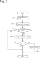
- Fig. 3 is an inclination detection flowchart according to the first embodiment. The following flow is automatically started when a power supply is turned on, when the apparatus is not used for a predetermined period of time, or when an inclination detection application is started.
- Step S101 the arithmetic processing unit 13 operates the adding/removing unit 18 to load/unload the built-in weight 17.
- the number of times of loading/unloading is set according to the resolution of the weight sensor 12. The higher the resolution is, the higher the sensitivity is, and therefore, it is also preferable that the accuracy is improved by increasing the number of times of loading/unloading.
- Step S102 the process shifts to Step S102, and the arithmetic processing unit 13 acquires a weighing value F' of the built-in weight 17.
- the built-in weight change amount computing unit 131 reads the theoretical value F of the built-in weight 17 from the memory 14, and computes a built-in weight change amount F-F'.
- the built-in weight change amount F-F' does not exceed an allowable range (Yes)
- the process shifts to Step S104.
- the process shifts to Step S105, and the inclination angle determining unit 134 functions and reads the allowable inclination threshold ⁇ s of inclination angle from the memory 14, and compares it with the apparatus inclination angle ⁇ obtained in Step S104.
- the allowable inclination threshold ⁇ s can be determined from measurement specifications of the balance 10 and is set in advance, or it may be set by a user according to weighing way.
- the inclination angle ⁇ does not exceed the allowable inclination threshold ⁇ s (Yes)
- the inclination angle ⁇ exceeds the allowable inclination threshold ⁇ s No
- it is determined that the apparatus needs to be leveled has a problem
- the process shifts to Step S106.
- the warning unit 137 functions and displays a warning to prompt leveling on the display unit 16.
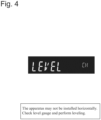
- Fig. 4 illustrates an example of warning display according to the first embodiment.
- the warning unit 137 displays "LEVEL CH" as an abbreviation for Level check.
- the display unit 16 is a liquid crystal screen, text to prompt leveling is displayed.
- the built-in weight 17 whose theoretical value has been stored in advance in the memory 14 for automatic calibration is focused, and automatic inclination detection is performed by obtaining an inclination angle of the balance 10 by using a weighing error of the built-in weight 17.
- the built-in weight 17 is loaded/unloaded onto/from the same location (fixed position) by the adding/removing unit 18.
- the balance 10 uses a weighing value of the built-in weight 17 for inclination detection, and a weighing value can be obtained with high reproducibility, and according to this, an inclination angle can be calculated with high accuracy.
- Fig. 5 is a configuration block diagram of a weighing apparatus according to a second embodiment.
- the same reference signs are cited, and description of the components are omitted.
- the weighing apparatus according to the second embodiment includes the weighing pan 11, the weight sensor 12, the arithmetic processing unit 13, the memory 14, the key switches 15, the display unit 16, the built-in weight 17, the adding/removing unit 18, and further, a temperature sensor 19.
- the temperature sensor 19 detects a temperature of an environment in which the balance 10' is disposed. Temperature data output from the temperature sensor 19 is A/D converted and output to the arithmetic processing unit 13.
- the arithmetic processing unit 13 includes the built-in weight change amount computing unit 131, the inclination angle computing unit 133, the inclination angle determining unit 134, the warning unit 137, and further, a sensitivity drift computing unit 132 and a sensitivity drift determining unit 135. Details of the respective functions will be described later.
- a theoretical value F of the built-in weight, an allowable threshold ⁇ s of inclination angle, a specification value x of sensitivity drift, and an allowable drift threshold xs of sensitivity drift are stored. Further, in the memory 14, each time a calibration is executed, a temperature measurement value of the temperature sensor 19 at the time of the calibration is stored.
- a weighing value error of the balance will be further considered.
- Causes of a change in weighing value from a true value include, in addition to an inclination error, sensitivity drift of the weight sensor caused by a temperature change.
- Concerning the sensitivity drift specifications have been determined for each balance, so that a maximum value according to a sensitivity change can be obtained.
- a maximum value of a weighing value change amount caused by sensitivity drift is obtained by a numerical expression 2.
- inclination detection is performed by utilizing a maximum value of sensitivity drift (a weighing value change amount caused by a temperature change) and taking into consideration a sensitivity change caused by the temperature change.
- Fig. 6 is an inclination detection flowchart according to the second embodiment.
- Figs. 7, 8 , and 9 illustrate examples of warning display according to the second embodiment.
- the following flow is automatically started when a power supply is turned on, when the apparatus is not used for a predetermined period of time, or when an inclination detection application is started.
- the same reference signs are cited, and description of the steps are omitted.
- Step S201 the arithmetic processing unit 13 operates the adding/removing unit 18 to load/unload the built-in weight 17 as in Step S101.
- Step S202 the process shifts to Step S202, and the arithmetic processing unit 13 acquires a weighing value F' of the built-in weight 17 as in Step S102.
- Step S203 the process shifts to Step S203, and the built-in weight change amount computing unit 131 computes a built-in weight change amount F-F' as in Step S103.
- the built-in weight change amount F-F' does not exceed an allowable range (Yes)
- it is determined that the built-in weight change amount F-F' poses no problem in weighing and the process ends .
- the process shifts to Step S204.
- the sensitivity drift computing unit 132 functions and acquires a current temperature measurement value from the temperature sensor 19, reads a temperature measurement value in a previous calibration and the sensitivity drift specification value x from the memory 14, and computes a sensitivity drift value (a maximum value of a weighing value change amount caused by the temperature change) W T from the numerical expression 2.
- Step S205 the process shifts to Step S205, and from a numerical expression 3, the inclination angle computing unit 133 calculates an apparatus inclination angle ⁇ by subtracting the sensitivity drift value.
- ⁇ cos ⁇ 1 F ′ F ⁇ W T
- Step S206 the process shifts to Step S206, and the inclination angle determining unit 134 functions and reads the allowable inclination threshold ⁇ s of inclination angle from the memory 14, and compares it with the apparatus inclination angle ⁇ obtained in Step S205.
- ⁇ does not exceed ⁇ s (Yes)
- ⁇ exceeds ⁇ s (No)
- it is determined that there is a problem with the inclination angle and/or sensitivity drift and the process shifts to Step S209.
- the sensitivity drift determining unit 135 When the process shifts to Step S207, it has been determined that there is no problem with the inclination, so that the sensitivity drift determining unit 135 functions and checks whether there is a problem with the sensitivity drift.
- the sensitivity drift determining unit 135 reads the allowable drift threshold xs from the memory 14 and compares it with the sensitivity drift value W T obtained in Step S204.
- W T does not exceed xs (Yes)
- W T does not exceed xs (Yes)
- W T it is determined that neither the inclination nor the sensitivity drift poses a problem in weighing, and the process ends as is, or the fact that weighing is normal is displayed and the process ends.
- W T exceeds xs No
- it is determined that there is no problem with the inclination but there is a problem with the sensitivity drift and the process shifts to Step S208.
- Step S208 since it has been determined that there is a problem with the sensitivity drift, a calibration to eliminate the sensitivity drift needs to be executed.
- Fig. 7 illustrates an example of warning display in Step S208.
- the warning unit 137 displays "CAL CH" as an abbreviation for Calibration check.
- the display unit 16 is a liquid crystal touch panel, text to prompt a calibration is displayed.
- the sensitivity drift determining unit 135 functions, and as in Step S207, checks whether there is a problem with the sensitivity drift.
- W T does not exceed xs (Yes)
- the process shifts to Step S210.
- W T exceeds xs in Step S209 (No)
- Step S210 it has been determined that there is no problem with the sensitivity drift and there is a problem with the inclination, so that it is necessary to execute leveling.
- Fig. 8 illustrates an example of warning display in Step S210.
- the warning unit 137 displays "LEVEL CH" as an abbreviation for Level check.
- the display unit 16 is a liquid crystal touch panel, text to prompt leveling is displayed.
- Step S211 it has been determined that there are problems with both inclination and sensitivity drift, so that it is necessary to execute both leveling and calibration.
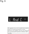
- Fig. 9 illustrates an example of warning display in Step S211.
- the warning unit 137 displays "L And C CH" as an abbreviation for Level and Calibration check.
- the display unit 16 is a liquid crystal touch panel, text to prompt leveling and a calibration after leveling is displayed.
- inclination detection is performed by obtaining an inclination angle of the balance 10' after eliminating a sensitivity drift maximum value by using also a value of the temperature sensor 19. Then, the apparatus automatically determines whether a weighing error is due to an inclination or a sensitivity change caused by a temperature change, and issues a warning according to the determination.
- the temperature sensor 19 is mounted in advance on many balances basically for automatic calibration, so that software processes of the sensitivity drift computing unit 132 and the sensitivity drift determining unit 135 are only added to the arithmetic processing unit 13 of the balance 10' , and the number of assembling components (hardware components) of the balance 10' does not differ from that of an existing balance. Therefore, even further taking into consideration a temperature change in addition to the inclination detection, the number of components of the balance 10' of the present embodiment does not increase.
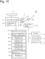
- Fig. 10 is a configuration block diagram of a weighing apparatus according to a third embodiment.
- the same reference signs are cited, and description of the components are omitted.
- the weighing apparatus includes, as in the second embodiment, the weighing pan 11, the weight sensor 12, the arithmetic processing unit 13, the memory 14, the key switches 15, the display unit 16, the built-in weight 17, the adding/removing unit 18, and the temperature sensor 19.
- the arithmetic processing unit 13 includes the built-in weight change amount computing unit 131, the sensitivity drift computing unit 132, the inclination angle computing unit 133, the inclination angle determining unit 134, the sensitivity drift determining unit 135, the warning unit 137, and further, an inclination angle additional determining unit 136. Details of this function will be described later.
- a weighing value error of the balance will be further considered.
- causes of a change in weighing value from a true value include, in addition to an inclination error and sensitivity drift caused by a temperature change, a change in gravitational acceleration caused by an installation location change.
- the inclination detection is performed so that, when the inclination determination result is clearly abnormal, a change in gravitational acceleration is suspected.
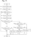
- Fig. 11 is an inclination detection flowchart according to the third embodiment. The following flow is automatically started when a power supply is turned on, when the apparatus is not used for a predetermined period of time, or when an inclination detection application is started. For the same steps as in the second embodiment, the same reference signs are cited, and description of the steps are omitted.
- the arithmetic processing unit 13 performs the same processes as in Steps S201 to S205 of the second embodiment in Steps S301 to S305. That is, the built-in weight 17 is loaded/unloaded in Step S301, a weighing value F' of the built-in weight 17 is acquired in Step S302, a built-in weight change amount F-F' is computed in Step S303, a sensitivity drift W T is computed from the numerical expression 2 in Step S304, and in Step S305, from the numerical expression 3, an apparatus inclination angle ⁇ is calculated by subtracting the sensitivity drift value.
- Step S306 the process shifts to Step S306, and the inclination angle determining unit 134 performs the same process as in Step S206 as "Inclination angle determination 1." That is, the inclination angle determining unit 134 reads the allowable inclination threshold ⁇ s1 of inclination angle from the memory 14, compares the inclination angle ⁇ obtained in Step S305 with the allowable inclination threshold ⁇ s1, and when ⁇ does not exceed ⁇ s1 (Yes), the process shifts to Step S307, and when ⁇ exceeds ⁇ s1 (No), the process shifts to Step S309.
- the sensitivity drift determining unit 135 checks whether there is a problem with the sensitivity drift by comparing the sensitivity drift value W T obtained in Step S304 with the allowable drift threshold xs. When W T does not exceed xs (Yes), it is determined that neither the inclination nor the sensitivity drift poses a problem in weighing, and the process ends as is, or the fact that weighing is normal is displayed and the process ends.
- Step S308 the warning unit 137 issues a warning to prompt a calibration to eliminate the sensitivity drift ( Fig. 7 ) .
- the inclination angle additional determining unit 136 functions.
- the inclination angle additional determining unit 136 reads the inclination abnormality threshold ⁇ s2 of inclination angle from the memory 14, and compares the inclination angle ⁇ obtained in Step S305 with the inclination abnormality threshold ⁇ s2 of inclination angle.
- the inclination abnormality threshold ⁇ s2 of inclination angle is set to a value showing a clearly large inclination. For example, when the inclination angle is 5°, the apparatus has reached a state where the apparatus has such an inclination that an operator can know by a visual check, and it is considered normally impossible that the inclination angle ⁇ exceeds the inclination abnormality threshold ⁇ s2. Therefore, when the inclination angle ⁇ calculated in Step S305 exceeds the inclination abnormality threshold ⁇ s2, the inclination is determined to be clearly abnormal, and another cause, that is, a change in gravitational acceleration is suspected.
- Step S309 when ⁇ exceeds ⁇ s2 (No), the inclination is determined to be excessively large, and a change in gravitational acceleration is suspected in addition to the inclination, and the process shifts to Step S312.
- the warning unit 137 issues a warning to prompt both leveling and calibration to correct both inclination and change in gravitational acceleration that are likely to have occurred ( Fig. 9 ).
- Step S309 when ⁇ does not exceed ⁇ s2 (Yes), the inclination is determined not to be clearly abnormal, and whether there is a problem with the sensitivity drift is checked as in Steps S209 to S211. That is, in Step S310, the sensitivity drift determining unit 135 checks the sensitivity drift, and when there is no problem with the sensitivity drift (W T does not exceed xs, Yes), it is determined that there is a problem with the inclination, and the warning unit 137 issues a warning to prompt leveling ( Fig. 8 ).
- the warning unit 137 issues a warning to prompt both leveling and calibration ( Fig. 9 ).
- an inclination abnormality threshold ⁇ s2 for suspecting a change in gravitational acceleration is set, and the apparatus automatically determines whether a weighing error is due to an inclination, a sensitivity change, or a change in gravitational acceleration, and issues a warning according to the determination.
- a software process of the inclination angle additional determining unit 136 is only added to the arithmetic processing unit 13 of the balance 10, and the number of assembling components (hardware components) does not differ from that of an existing balance. Therefore, even further taking into consideration a temperature change and a change in gravitational acceleration in addition to the inclination detection, the number of components of the balance 10 of the present embodiment does not increase.
Landscapes
- General Physics & Mathematics (AREA)
- Physics & Mathematics (AREA)
- Engineering & Computer Science (AREA)
- Theoretical Computer Science (AREA)
- Mathematical Optimization (AREA)
- General Engineering & Computer Science (AREA)
- Pure & Applied Mathematics (AREA)
- Computational Mathematics (AREA)
- Mathematical Analysis (AREA)
- Radar, Positioning & Navigation (AREA)
- Emergency Management (AREA)
- Business, Economics & Management (AREA)
- Remote Sensing (AREA)
- Indication And Recording Devices For Special Purposes And Tariff Metering Devices (AREA)
- Arrangements For Transmission Of Measured Signals (AREA)
Applications Claiming Priority (1)
| Application Number | Priority Date | Filing Date | Title |
|---|---|---|---|
| PCT/JP2020/016508 WO2021210084A1 (fr) | 2020-04-15 | 2020-04-15 | Procédé de détection d'inclinaison et dispositif correspondant |
Publications (2)
| Publication Number | Publication Date |
|---|---|
| EP4137787A1 true EP4137787A1 (fr) | 2023-02-22 |
| EP4137787A4 EP4137787A4 (fr) | 2023-06-14 |
Family
ID=78083637
Family Applications (1)
| Application Number | Title | Priority Date | Filing Date |
|---|---|---|---|
| EP20930978.0A Withdrawn EP4137787A4 (fr) | 2020-04-15 | 2020-04-15 | Procédé de détection d'inclinaison et dispositif correspondant |
Country Status (5)
| Country | Link |
|---|---|
| US (1) | US12345561B2 (fr) |
| EP (1) | EP4137787A4 (fr) |
| JP (1) | JP6990486B1 (fr) |
| KR (1) | KR20230002338A (fr) |
| WO (1) | WO2021210084A1 (fr) |
Families Citing this family (2)
| Publication number | Priority date | Publication date | Assignee | Title |
|---|---|---|---|---|
| US20230392973A1 (en) * | 2022-06-02 | 2023-12-07 | Electronic Theatre Controls, Inc. | Intelligent digital load cell transducer |
| CN117470194B (zh) * | 2023-12-28 | 2024-04-09 | 江西飞尚科技有限公司 | 一种倾角测量方法、系统、存储介质及计算机 |
Family Cites Families (15)
| Publication number | Priority date | Publication date | Assignee | Title |
|---|---|---|---|---|
| US3826319A (en) * | 1973-06-27 | 1974-07-30 | Reliance Electric Co | Scale motion detector |
| DE3639521C2 (de) * | 1986-11-20 | 1994-03-17 | Sartorius Gmbh | Elektrische Waage |
| US4750574A (en) * | 1987-02-02 | 1988-06-14 | General Oceanics, Inc. | Accurate weight determination at sea |
| JPH04501176A (ja) * | 1989-05-09 | 1992-02-27 | ワース・ガロー・メステクニツク・アクチエンゲゼルシヤフト | 軸ばね秤 |
| JPH071195B2 (ja) * | 1989-12-29 | 1995-01-11 | 株式会社島津製作所 | 校正分銅内蔵形電子天びん |
| IL105508A (en) | 1993-04-23 | 1996-03-31 | Zfira Uri | Level weighing device |
| US6137065A (en) * | 1993-04-23 | 2000-10-24 | Zefira; Uri | Level weighing device |
| JP2003254818A (ja) * | 2002-03-04 | 2003-09-10 | Shimadzu Corp | 電子天秤/電子はかり |
| DE502004005293D1 (de) * | 2004-12-23 | 2007-11-29 | Mettler Toledo Ag | Kalibriergewichtsanordnung für eine elektronische Waage |
| DE102006059261B4 (de) | 2006-12-15 | 2010-09-09 | Sartorius Ag | Elektronische Waage mit einem Neigungsmesser und zugehöriges Verfahren zur Signalauswertung |
| JP4940026B2 (ja) * | 2007-06-15 | 2012-05-30 | 株式会社タニタ | 生体測定装置 |
| JP2010078439A (ja) | 2008-09-25 | 2010-04-08 | Tanita Corp | 電子重量計および傾斜検知方法 |
| GB2469823B (en) * | 2009-04-28 | 2011-07-06 | Illinois Tool Works | Weighing method and apparatus |
| CN105333862B (zh) | 2014-08-08 | 2018-05-25 | 梅特勒-托利多仪器(上海)有限公司 | 测量水准泡气泡位置的设备和方法及包含该设备的水准泡 |
| CN105571691A (zh) | 2014-10-09 | 2016-05-11 | 梅特勒-托利多(常州)精密仪器有限公司 | 称重传感器、称重网络及监测方法 |
-
2020
- 2020-04-15 JP JP2020555536A patent/JP6990486B1/ja active Active
- 2020-04-15 KR KR1020227033385A patent/KR20230002338A/ko not_active Ceased
- 2020-04-15 US US17/914,665 patent/US12345561B2/en active Active
- 2020-04-15 WO PCT/JP2020/016508 patent/WO2021210084A1/fr not_active Ceased
- 2020-04-15 EP EP20930978.0A patent/EP4137787A4/fr not_active Withdrawn
Also Published As
| Publication number | Publication date |
|---|---|
| JP6990486B1 (ja) | 2022-01-13 |
| EP4137787A4 (fr) | 2023-06-14 |
| KR20230002338A (ko) | 2023-01-05 |
| US20230126732A1 (en) | 2023-04-27 |
| JPWO2021210084A1 (fr) | 2021-10-21 |
| US12345561B2 (en) | 2025-07-01 |
| WO2021210084A1 (fr) | 2021-10-21 |
Similar Documents
| Publication | Publication Date | Title |
|---|---|---|
| US7497137B2 (en) | Method of monitoring and/or determining the condition of a force-measuring device, and force-measuring device | |
| EP0132054B1 (fr) | Balance électronique | |
| US8055456B2 (en) | Method of monitoring and/or determining the condition of a force-measuring device, and force-measuring device | |
| US12345561B2 (en) | Inclination detecting method and apparatus for the same | |
| GB2469823A (en) | Method and apparatus for calibrating a weighing scale to compensate for inclination errors | |
| JP3199129B2 (ja) | 力または荷重センサの故障自己復帰装置 | |
| US4776215A (en) | Dynamic balancing system and method | |
| KR20070024656A (ko) | 전자 나침반의 판독성을 개선하는 시스템, 방법, 장치 및컴퓨터 코드 생성물 | |
| JPH10142347A (ja) | 感震装置 | |
| KR20030074177A (ko) | 수준기 | |
| JP4508398B2 (ja) | 電子天びん | |
| JP7685779B2 (ja) | 三軸加速度センサを利用した計量装置および計量方法 | |
| JP4801020B2 (ja) | 重量測定装置 | |
| EP3882583B1 (fr) | Appareil de pesée | |
| JP2003035592A (ja) | 計量装置 | |
| JP3163448U (ja) | 電子秤 | |
| CN87102305A (zh) | 电子天平 | |
| JP2008202939A (ja) | 電子天びん | |
| JP7688334B2 (ja) | 三軸加速度センサを搭載した計量装置およびその点検方法 | |
| EP4141391B1 (fr) | Appareil de pesage | |
| JP3139390U (ja) | 電子天秤 | |
| JP2001059769A (ja) | ロードセル秤 | |
| JP2004264107A (ja) | 保守点検支援装置 | |
| JP3018753B2 (ja) | セル寿命予測システム | |
| EP3859399A1 (fr) | Informations de cap d'informations basées sur la détection de satellite unique |
Legal Events
| Date | Code | Title | Description |
|---|---|---|---|
| STAA | Information on the status of an ep patent application or granted ep patent |
Free format text: STATUS: THE INTERNATIONAL PUBLICATION HAS BEEN MADE |
|
| PUAI | Public reference made under article 153(3) epc to a published international application that has entered the european phase |
Free format text: ORIGINAL CODE: 0009012 |
|
| STAA | Information on the status of an ep patent application or granted ep patent |
Free format text: STATUS: REQUEST FOR EXAMINATION WAS MADE |
|
| 17P | Request for examination filed |
Effective date: 20221114 |
|
| AK | Designated contracting states |
Kind code of ref document: A1 Designated state(s): AL AT BE BG CH CY CZ DE DK EE ES FI FR GB GR HR HU IE IS IT LI LT LU LV MC MK MT NL NO PL PT RO RS SE SI SK SM TR |
|
| A4 | Supplementary search report drawn up and despatched |
Effective date: 20230512 |
|
| RIC1 | Information provided on ipc code assigned before grant |
Ipc: G01G 23/00 20060101ALI20230508BHEP Ipc: G01G 23/01 20060101AFI20230508BHEP |
|
| DAV | Request for validation of the european patent (deleted) | ||
| DAX | Request for extension of the european patent (deleted) | ||
| STAA | Information on the status of an ep patent application or granted ep patent |
Free format text: STATUS: THE APPLICATION IS DEEMED TO BE WITHDRAWN |
|
| 18D | Application deemed to be withdrawn |
Effective date: 20231212 |