EP4137831A1 - Procédé de détermination de l'état de santé d'un accumulateur - Google Patents
Procédé de détermination de l'état de santé d'un accumulateur Download PDFInfo
- Publication number
- EP4137831A1 EP4137831A1 EP21192300.8A EP21192300A EP4137831A1 EP 4137831 A1 EP4137831 A1 EP 4137831A1 EP 21192300 A EP21192300 A EP 21192300A EP 4137831 A1 EP4137831 A1 EP 4137831A1
- Authority
- EP
- European Patent Office
- Prior art keywords
- accumulator
- value
- voltage
- battery
- current
- Prior art date
- Legal status (The legal status is an assumption and is not a legal conclusion. Google has not performed a legal analysis and makes no representation as to the accuracy of the status listed.)
- Withdrawn
Links
Images


Classifications
-
- G—PHYSICS
- G01—MEASURING; TESTING
- G01R—MEASURING ELECTRIC VARIABLES; MEASURING MAGNETIC VARIABLES
- G01R31/00—Arrangements for testing electric properties; Arrangements for locating electric faults; Arrangements for electrical testing characterised by what is being tested not provided for elsewhere
- G01R31/36—Arrangements for testing, measuring or monitoring the electrical condition of accumulators or electric batteries, e.g. capacity or state of charge [SoC]
- G01R31/392—Determining battery ageing or deterioration, e.g. state of health
-
- G—PHYSICS
- G01—MEASURING; TESTING
- G01R—MEASURING ELECTRIC VARIABLES; MEASURING MAGNETIC VARIABLES
- G01R31/00—Arrangements for testing electric properties; Arrangements for locating electric faults; Arrangements for electrical testing characterised by what is being tested not provided for elsewhere
- G01R31/36—Arrangements for testing, measuring or monitoring the electrical condition of accumulators or electric batteries, e.g. capacity or state of charge [SoC]
- G01R31/382—Arrangements for monitoring battery or accumulator variables, e.g. SoC
- G01R31/3842—Arrangements for monitoring battery or accumulator variables, e.g. SoC combining voltage and current measurements
-
- G—PHYSICS
- G01—MEASURING; TESTING
- G01R—MEASURING ELECTRIC VARIABLES; MEASURING MAGNETIC VARIABLES
- G01R31/00—Arrangements for testing electric properties; Arrangements for locating electric faults; Arrangements for electrical testing characterised by what is being tested not provided for elsewhere
- G01R31/36—Arrangements for testing, measuring or monitoring the electrical condition of accumulators or electric batteries, e.g. capacity or state of charge [SoC]
- G01R31/389—Measuring internal impedance, internal conductance or related variables
-
- H—ELECTRICITY
- H02—GENERATION; CONVERSION OR DISTRIBUTION OF ELECTRIC POWER
- H02J—ELECTRIC POWER NETWORKS; CIRCUIT ARRANGEMENTS OR SYSTEMS FOR SUPPLYING OR DISTRIBUTING ELECTRIC POWER; SYSTEMS FOR STORING ELECTRIC ENERGY
- H02J7/00—Circuit arrangements for charging or discharging batteries or for supplying loads from batteries
- H02J7/80—Circuit arrangements for charging or discharging batteries or for supplying loads from batteries including monitoring or indicating arrangements
- H02J7/84—Control of state of health [SOH]
Definitions
- the present invention relates to a method for controlling and regulating an accumulator for supplying a machine tool with electrical energy, the accumulator containing at least one energy storage cell, at least one temperature sensor, a current measuring device, a voltage measuring device and a battery control device with at least one battery storage device.
- the present invention relates to an accumulator for carrying out the method.
- the present invention relates to a charging device for carrying out the method.
- Accumulators are often used to supply different devices or machines with electrical energy.
- the use of accumulators to supply power to machine tools, such as drills, hammer drills, saws, grinders, screwdrivers or the like, is also widely known.
- Accumulators usually have a large number of energy storage cells (also called cells or accumulator cells) for storing or providing the electrical energy.
- the technology of the energy storage cells can be based, for example, on Li-Ion, Li-Polymer, Li-Metal, Ni-Cd, Ni-MH or the like.
- SOH Stable Health
- the correct and precise determination of the actual capacity or the SOH of an accumulator is also necessary in order to be able to determine the necessary charging amount of electrical energy and the actual charging time for fast and effective charging of the accumulator when the accumulator is charged by a charger .
- the object is achieved by a method for controlling and regulating an accumulator for supplying a machine tool with electrical energy, the accumulator containing at least one energy storage cell, at least one temperature sensor, a current measuring device, a voltage measuring device and a battery control device with at least one battery storage device .
- the actual capacity and performance of the accumulator can be determined by the determined impedance or internal resistance value. The higher the impedance or the internal resistance of the battery, the lower the capacity and performance of the battery.
- the actual capacity and performance of the accumulator can also be referred to as the state of health (SoH) of the accumulator.
- the process step of setting the accumulator from a first state of charge to a second state of charge can be either a charging process, in which electrical energy is transferred from a charger to the accumulator, or a discharging process, in which electrical energy is transferred from the accumulator to a machine tool arrived, act.
- the first voltage value may be determined after a third predetermined period of time has elapsed after the first current value has been reached.
- the third predetermined period of time is between 1 and 5 seconds, in particular 3 seconds, and is used for relaxation and thus for a more precise determination of the battery or cell voltage.
- the specific voltage of the battery i.e. the maximum, nominal or minimum voltage, results from the respective battery cell technology and the number of battery cells that are connected in series inside the battery.
- the capacity is typically specified or measured in ampere-hours (Ah) and describes the electrical charge that the battery can contain. It is calculated from the capacity of a single battery cell and from the number of battery cells that are connected in parallel (or connected in parallel) in the battery. For a given battery voltage, a higher capacity means that the battery can store more energy.
- the maximum current that an accumulator can supply is specified. Since the battery cells heat up at high currents and can only be operated in a certain temperature range, the performance of the battery can also be described by a current that the battery can deliver for a certain time or until it is completely discharged. The performance is very much dependent on the impedance (alternating current resistance) of the accumulator.
- the impedance can also be defined as the internal resistance of the battery cells or the accumulator.
- Accumulators for supplying a machine tool typically contain lithium ion cells (Li-Ion), which are usually charged with electrical energy using conventional chargers in what is known as a CCCV process (constant current: constant current strength; constant voltage: constant voltage).
- the charging electronics of the charger generate a constant charging current through the accumulator (constant current - CC), so that the accumulator voltage increases. As soon as a maximum battery voltage is reached, this is kept constant by the charging electronics (Constant Voltage - CV) and the charging current is reduced accordingly. If a predefined minimum value of the charging current is reached, the charging electronics end the charging process and the battery cells are fully charged.
- the transition from the CC phase to the CV phase typically occurs at a state of charge (i.e. capacity) of about 80%.
- the battery voltage of the battery is usually a multiple of the voltage of an individual battery cell and results from the parallel or serial connection of the battery cells.
- exemplary battery voltages of 3.6V, 7.2V, 10.8V, 14.4V, 18V, 36V etc. are obtained formed at least substantially cylindrical round cell, wherein the cell poles are arranged at ends of the cylindrical shape.
- the electrical interface comprises at least two electrical contact elements that are designed to transmit energy.
- the electrical interface can also have a secondary charging coil element for inductive charging.
- the charging process is carried out using the CCCV method, with the first charge value being determined before the CC phase and the further charge values during the CC phase and the CV phase to determine the remaining capacity.
- the open-circuit voltage is measured and then a so-called “coulumb counting” is carried out, which records the number of electrons to determine the charge in the accumulator.
- the remaining capacity of the accumulator is preferably determined during the CC phase, in that the charging current is reduced from a first value to a second value for a specific period of time after the predefined accumulator voltage has been reached.
- the remaining capacity of the accumulator one Waiting time after changing the charging current until the battery voltage is measured.
- the determination of the remaining capacity is repeated at regular time intervals during the charging process, in particular during the CC phase.
- the increase in impedance over time is an effect of the aging of the battery cells.
- the impedance of the current-carrying elements (contacts, conductor tracks, cables, etc.) in the accumulator or in the charger changes only negligibly. It is therefore particularly advantageous to carry out the voltage measurements directly in the accumulator in order to ignore the impedances of the current-carrying elements. Either the voltage in the individual battery cells or the voltage in the entire battery can be determined. This impedance measurement can take place either once or several times during the charging process. Several measurements allow a plausibility check and thus avoid measurement errors, but also a more precise and detailed estimation.
- the remaining capacity, the remaining performance and/or the state of health of the accumulator can be output on an external display unit with particular advantage.
- a display LCD, OLED, ePaper or the like
- LED display of the rechargeable battery the charger or alternatively or additionally a smartphone, tablet, PC or the like
- the communication between the accumulator and the indicated display units takes place via a corresponding communication interface.
- a proprietary BUS can be used here, such as transmission using standard protocols by cable or radio.
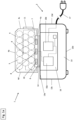
- Figure 1a shows an accumulator 1 releasably connected to a charger 2.
- the accumulator 1 can be used as an energy supply for a machine tool 3 .
- the machine tool 3 is in the form of a cordless screwdriver figure 2 shown.
- the rechargeable battery 1 essentially contains a rechargeable battery housing 4, a number of energy storage cells 5, a rechargeable battery interface 6, a current measuring device 7, a voltage measuring device 8, a temperature sensor 9, a rechargeable battery storage device 10, a display and input device 11 and a Battery control device 12.
- the battery case 4 includes a top 4a, a bottom 4b, a left side wall, a right side wall, a front 4c, and a back.
- a top 4a, a bottom 4b, the front 4c and the back 4d are shown.
- the battery interface 6 is positioned on the top 4a of the battery housing 4 and is used to releasably connect the battery 3 to the charger 2 or a machine tool 3.
- the battery interface 6 contains a mechanical coupling device, an electrical connection device and a communication port . Neither the mechanical coupling device, the electrical connection device nor the communication port is shown in the figures.
- the mechanical coupling device, the electrical connection device and the communication connection of the battery interface 6 are not shown in the figures.
- the accumulator 1 can be connected to the charging device 2 or to a machine tool 3 in a positive and non-positive manner by means of the mechanical coupling device. With the help of the electrical connection device, electrical energy can get from the charger 2 to the rechargeable battery 1 when the rechargeable battery 1 is connected to the charger 2 . Likewise, electrical energy can reach a machine tool 3 from the accumulator 1 if the accumulator 1 is connected to the machine tool 3 .
- the communication connection is used to enable information and data to be exchanged in the form of signals between the accumulator 1 and the charging device 2 or between the accumulator 1 and the machine tool 3 .
- the information and data can include charging or discharging parameters, Temperature values, state of charge (SOC), state of health (SOH), (residual) capacity, voltage, current or the like.
- the battery control device 12 is positioned essentially near the top of the battery housing 4 and is used to control and regulate the various functions of the battery 1.
- the energy storage cells 5 are positioned in three rows inside the battery housing 4 so that the temperature sensor 9 is positioned between the second and third row of the energy storage cells 5 .
- the temperature sensor 9 serves to detect the temperature inside the accumulator 1 at one of the centrally positioned energy storage cells 5.
- the temperature sensor 9 is connected to the accumulator control device 12 via a line. Since the energy storage cells 5 inside or in the middle of the accumulator 1 usually have the highest temperatures during the charging or discharging process, a temperature sensor 9, which detects the temperature at this centrally positioned energy storage cell 5, can measure the highest temperature and thus the fastest determine a critically high temperature for accumulator 1.
- the current measuring device 7 , the voltage measuring device 8 and the rechargeable battery storage device 10 are contained within the rechargeable battery control device 12 .
- the current measuring device 7 serves to detect or measure the current intensity at the individual energy storage cells 5. As in Figure 1a The current measuring device 7 is therefore indicated as being connected to each individual energy storage cell 5 . The current intensity for the entire accumulator 1 can be determined by detecting or measuring the current intensity at the individual energy storage cell 5 .
- the voltage measuring device 8 is used to detect or measure the voltage at the individual energy storage cells 5. As in Figure 1a the voltage measuring device 8 is therefore indicated as being connected to each individual energy storage cell 5 . The voltage for the entire accumulator 1 can be determined by detecting or measuring the voltage at the individual energy storage cell 5 .
- the storage device 10 is used to store and provide a wide variety of information and data, such as look-up tables for the various charging or discharging parameters of the accumulator 1. These parameters include, among other things, temperature profiles or threshold values for voltages or currents.
- the display and input device 11 which can also be referred to as a human-machine interface (HMI), is positioned on the front of the battery housing 4. As in Figure 1a The display and input device 11 is indicated as being connected to the battery control device 12 so that different data and information can be seen on a display portion of the display and input device 11 . In particular, the state of charge or the capacity of the accumulator 1 can be displayed on the display part.
- HMI human-machine interface
- a user can select and set different operating states (or also called operating modes or modes) for the accumulator 1.
- the different operating states include, for example, certain charging or discharging states.
- a CCCV charging method is set for the accumulator 1 in a first selectable operating state.
- a rapid charging method is set for the accumulator 1, in which a relatively short charging time can be achieved with relatively high charging currents.
- a slow and gentle charging process is set for the accumulator 1, in which a relatively long charging time can be achieved with relatively low charging currents, but charging that is gentle (i.e. less stressful) on the energy storage cells 5 can also be achieved.
- the charger 2 includes a charger housing 13, a charger interface 14, a charger storage device 15 and a charger control device 16.
- the charger control device 16 contains a current measuring device 16a and a voltage measuring device 16b.
- the charger case 13 includes a top 13a, a bottom 13b, a left side wall, a right side wall, a front 13c and a back 13d.
- a top 13a, a bottom 13b, front 13c and back 13d are shown.
- the charger interface 14 is positioned on the top 13a of the charger housing 13 and is used to releasably connect the charger 2 to the battery 1.
- the charger interface 14 contains a mechanical coupling device, an electrical connection device and a communication port.
- the mechanical coupling device, the electrical connection device and the communication port of the charger 2 are to the mechanical Coupling device, the electrical connection device and the communication port of the battery 1 configured correspondingly, so that the components of the charger interface 14 and the battery interface 6 can be connected to each other accordingly.
- the mechanical coupling device, the electrical connection device and the communication port of the charger interface 14 are not shown in the figures.
- the charger 2 has a power connection cable 17 which protrudes from the charger housing 14 and is connected to the charger control device 16 .
- the power connection cable 17 is used to releasably connect the charger 2 to a mains power source (socket).
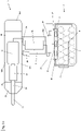
- figure 2 shows the accumulator 1 releasably connected to the machine tool 3.
- the machine tool 3 is in figure 2 designed as a cordless screwdriver.
- the machine tool 3 can also be designed as a rotary hammer, drill, saw, grinder or the like.
- the machine tool 3 designed as a cordless screwdriver essentially contains a housing 18, a handle 19 and a tool holder 20.
- the housing 18 of the machine tool 2 in turn contains a top 18a, a bottom 18b, a front end 18c and a rear end 18d.
- a drive 21, a gear 22, an output shaft 23 and a control device 24 are essentially included.
- the drive 21 is designed as an electric motor and is used to generate a torque.
- the gear 22, the output shaft 23 and the tool holder 20 arranged relative to each other that a torque generated by the drive 21 can be transmitted via the gear 22 and the output shaft 23 to the tool holder 20.
- the tool holder 20, which is used to receive and hold a tool 25, is positioned at the front end 18c.
- the tool 25 is a screwdriver bit.
- the handle 19 is used for holding and guiding the machine tool 3 by a user (not shown).
- the handle 19 includes an upper end 19a and a lower end 19b.
- the handle 19 is connected to the upper end 19a on the underside 19b of the housing 19 of the Machine tool 2 attached.
- a foot device 26 with a machine tool interface 27 is positioned at the lower end 19b of the handle 19 .
- the handle 19 has an activation switch 28 which is connected to the control device 24 .
- a user can use the activation switch 28 to put the machine tool 2 into an activation or deactivation state, depending on the positioning of the activation switch 28 .
- the drive 21 In an activated state, the drive 21 generates a torque.
- the machine tool interface 27 serves to connect the machine tool 3 to the battery 1 in a detachable manner.
- the machine tool interface 27 contains a mechanical coupling device, an electrical connection device and a communication connection.
- the mechanical coupling device, the electrical connection device and the communication connection of the machine tool 3 are designed to correspond to the mechanical coupling device, the electrical connection device and the communication connection of the rechargeable battery 1, so that the components of the machine tool 3 and the rechargeable battery interface 6 can be connected to one another accordingly.
- the mechanical coupling device, the electrical connection device and the communication connection of the machine tool 3 are not shown in the figures.
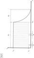
- figure 3 shows a graphic representation of a CCCV charging process, the charger 2 providing a constant charging current (CC - constant current) I C2 in phase P1 until a maximum battery voltage has been reached. From a point in time t end , the value of the charging current I C2 is continuously reduced during a second phase P2, with the battery voltage remaining constant (CV—constant voltage).
- CV constant voltage
- figure 2 shows a schematic diagram to show the method for controlling and regulating an accumulator 1 during charging of the accumulator 1.
- the accumulator 1 is first connected to the charger 2 in method step S1 in such a way that the corresponding mechanical coupling devices, the electrical connection devices and the communication connections of the accumulator 1 and the charger 2 are coupled to one another are.
- the communication connections of the accumulator 1 and the charger 2 data and information regarding the charging specification or charging parameters, in particular threshold values for a maximum charging current or a maximum charging voltage, are exchanged between the accumulator 1 and the charger 2.
- the electrical connection devices of the rechargeable battery 1 and the charging device 2 electrical energy is conducted from the charging device 2 to the rechargeable battery 1, with a value for a charging current intensity I C2 being set at the charging device 2.
- the value for the charging current I C2 is set by a corresponding signal from the accumulator 1 via the communication connections to the charger 2.
- the charging voltage U R1 at a charging current I C2 is recorded using the voltage measuring device 8 of the accumulator 1.
- the recorded value for the charging voltage U R1 is stored in the rechargeable battery storage device 10 .
- the recorded value for the charging voltage U R1 can be stored in the charger storage device 15 .
- a first current value I C1 is set for charging the accumulator 1, the first current value I C1 being lower than the charging current value I C2 set.
- the current value is set by the battery control device 12 or, according to an alternative embodiment of the invention, by the charger control device 16.
- the first current value I C1 can be 0A (in words: zero amperes).
- the first time period t1 is 5 to 10 seconds.
- the temperature of the accumulator 1 and the accumulator voltage or the charging voltage U R2 are recorded during the second method step S2.
- a first current value I C1 for charging the accumulator 1 is set.
- the impedance Z of the battery is determined from the quotient of the difference between the first current value I C1 and the second current value I C2 and the difference between the first voltage value U R1 and the second voltage value U R2 using formula F1.
- the second current value I C2 is set again to the first current value I C1 , cf. figure 4 .
- the impedance of the accumulator 1 is directly related to the temperature of the accumulator 1 or its energy storage cells 5.
- the temperature is therefore recorded with the temperature sensor 9 during the determination of the impedance in phase P1.
- the impedance can be determined as a function of the temperature of the accumulator 1 that is recorded in each case.
- the recorded temperature values are stored in the memory device.
- a normalized value for the impedance at a temperature of 25°C can be determined using the look-up tables for the temperature values.
- the impedance Z is determined at regular time intervals with the aid of the method described above.
- step D2 a decision is made as to whether the charging process for the accumulator 1 should be ended or not. If the charging process is to be continued, the impedance Z is determined again after a further period of time t1.
- the impedance values determined for phase P1 are stored in the memory device, so that a certain number of impedance values are present.
- a mean impedance value can be calculated from the large number of impedance values determined, which is relatively robust against possible state of charge and temperature dependencies.
- the capacity and performance of the accumulator 1 can be determined over the entire period of use of the accumulator by using a large number of calculated average impedance values.
- a decision can be made as to whether or not the average impedance value has reached a predetermined impedance threshold value.
- the predetermined impedance threshold is stored in the storage device. If the threshold value of the mean impedance determined has been reached, the capacity and performance of the accumulator 1 is no longer sufficient for further use as an energy supply for a machine tool 3 . The use, ie charging and discharging, of the rechargeable battery 1 can then be blocked by the control device 10 of the rechargeable battery 1 .
- the above method according to the invention describes a charging process for the accumulator 1 on the charger 2 .
- the method according to the invention can also be used for a discharging process for the accumulator 1 as an energy supply on a machine tool 3 .
- the procedure during a discharging process of the accumulator 1 is almost identical to the charging process of the accumulator 1.
- electrical energy arrives from the accumulator 1 to the machine tool 3 during the discharging process.
Landscapes
- Physics & Mathematics (AREA)
- General Physics & Mathematics (AREA)
- Engineering & Computer Science (AREA)
- Power Engineering (AREA)
- Charge And Discharge Circuits For Batteries Or The Like (AREA)
- Secondary Cells (AREA)
- Health & Medical Sciences (AREA)
- General Health & Medical Sciences (AREA)
- Medical Informatics (AREA)
Priority Applications (5)
| Application Number | Priority Date | Filing Date | Title |
|---|---|---|---|
| EP21192300.8A EP4137831A1 (fr) | 2021-08-20 | 2021-08-20 | Procédé de détermination de l'état de santé d'un accumulateur |
| PCT/EP2022/071790 WO2023020840A1 (fr) | 2021-08-20 | 2022-08-03 | Procédé de détermination de l'état d'une batterie rechargeable |
| CN202280047295.0A CN117597591A (zh) | 2021-08-20 | 2022-08-03 | 用于确定可充电电池的健康状态的方法 |
| EP22757974.5A EP4388332A1 (fr) | 2021-08-20 | 2022-08-03 | Procédé de détermination de l'état d'une batterie rechargeable |
| US18/681,779 US20240337702A1 (en) | 2021-08-20 | 2022-08-03 | Method for determining the state of health of a rechargeable battery |
Applications Claiming Priority (1)
| Application Number | Priority Date | Filing Date | Title |
|---|---|---|---|
| EP21192300.8A EP4137831A1 (fr) | 2021-08-20 | 2021-08-20 | Procédé de détermination de l'état de santé d'un accumulateur |
Publications (1)
| Publication Number | Publication Date |
|---|---|
| EP4137831A1 true EP4137831A1 (fr) | 2023-02-22 |
Family
ID=77431160
Family Applications (2)
| Application Number | Title | Priority Date | Filing Date |
|---|---|---|---|
| EP21192300.8A Withdrawn EP4137831A1 (fr) | 2021-08-20 | 2021-08-20 | Procédé de détermination de l'état de santé d'un accumulateur |
| EP22757974.5A Pending EP4388332A1 (fr) | 2021-08-20 | 2022-08-03 | Procédé de détermination de l'état d'une batterie rechargeable |
Family Applications After (1)
| Application Number | Title | Priority Date | Filing Date |
|---|---|---|---|
| EP22757974.5A Pending EP4388332A1 (fr) | 2021-08-20 | 2022-08-03 | Procédé de détermination de l'état d'une batterie rechargeable |
Country Status (4)
| Country | Link |
|---|---|
| US (1) | US20240337702A1 (fr) |
| EP (2) | EP4137831A1 (fr) |
| CN (1) | CN117597591A (fr) |
| WO (1) | WO2023020840A1 (fr) |
Cited By (1)
| Publication number | Priority date | Publication date | Assignee | Title |
|---|---|---|---|---|
| WO2025016507A1 (fr) * | 2023-07-14 | 2025-01-23 | Bayerische Motoren Werke Aktiengesellschaft | Procédé de détermination d'une résistance interne d'un élément de batterie d'un dispositif de stockage d'énergie pour un véhicule automobile pouvant être entraîné électriquement, programme informatique et/ou support lisible par ordinateur, dispositif de traitement de données, véhicule automobile pouvant être entraîné électriquement, colonne de charge |
Citations (4)
| Publication number | Priority date | Publication date | Assignee | Title |
|---|---|---|---|---|
| US5541490A (en) * | 1992-11-13 | 1996-07-30 | Zenith Data Systems Corporation | Computer power supply system |
| DE102018220251A1 (de) * | 2018-11-26 | 2020-05-28 | Robert Bosch Gmbh | Verfahren und Vorrichtung zur Abschätzung des Gesundheitszustands eines Wechselakkus |
| DE102019000754A1 (de) * | 2019-02-01 | 2020-08-06 | Diehl Aerospace Gmbh | Ermittlung der aktuellen Kapazität eines Akkumulators |
| WO2021063740A1 (fr) * | 2019-10-01 | 2021-04-08 | Hilti Aktiengesellschaft | Procédé de décharge efficace d'une batterie rechargeable |
Family Cites Families (5)
| Publication number | Priority date | Publication date | Assignee | Title |
|---|---|---|---|---|
| JP2005341759A (ja) * | 2004-05-28 | 2005-12-08 | Fuji Heavy Ind Ltd | ハイブリッド車のバッテリ管理装置 |
| JP2005341760A (ja) * | 2004-05-28 | 2005-12-08 | Fuji Heavy Ind Ltd | ハイブリッド車のバッテリ管理装置 |
| US10131042B2 (en) * | 2013-10-21 | 2018-11-20 | Milwaukee Electric Tool Corporation | Adapter for power tool devices |
| CN109932661B (zh) * | 2017-12-13 | 2022-02-08 | 宁德新能源科技有限公司 | 一种电池状态监测方法及装置 |
| WO2022030355A1 (fr) * | 2020-08-04 | 2022-02-10 | 株式会社Gsユアサ | Dispositif de stockage électrique, système de stockage électrique, procédé d'estimation de résistance interne et programme informatique |
-
2021
- 2021-08-20 EP EP21192300.8A patent/EP4137831A1/fr not_active Withdrawn
-
2022
- 2022-08-03 CN CN202280047295.0A patent/CN117597591A/zh active Pending
- 2022-08-03 WO PCT/EP2022/071790 patent/WO2023020840A1/fr not_active Ceased
- 2022-08-03 US US18/681,779 patent/US20240337702A1/en active Pending
- 2022-08-03 EP EP22757974.5A patent/EP4388332A1/fr active Pending
Patent Citations (4)
| Publication number | Priority date | Publication date | Assignee | Title |
|---|---|---|---|---|
| US5541490A (en) * | 1992-11-13 | 1996-07-30 | Zenith Data Systems Corporation | Computer power supply system |
| DE102018220251A1 (de) * | 2018-11-26 | 2020-05-28 | Robert Bosch Gmbh | Verfahren und Vorrichtung zur Abschätzung des Gesundheitszustands eines Wechselakkus |
| DE102019000754A1 (de) * | 2019-02-01 | 2020-08-06 | Diehl Aerospace Gmbh | Ermittlung der aktuellen Kapazität eines Akkumulators |
| WO2021063740A1 (fr) * | 2019-10-01 | 2021-04-08 | Hilti Aktiengesellschaft | Procédé de décharge efficace d'une batterie rechargeable |
Cited By (1)
| Publication number | Priority date | Publication date | Assignee | Title |
|---|---|---|---|---|
| WO2025016507A1 (fr) * | 2023-07-14 | 2025-01-23 | Bayerische Motoren Werke Aktiengesellschaft | Procédé de détermination d'une résistance interne d'un élément de batterie d'un dispositif de stockage d'énergie pour un véhicule automobile pouvant être entraîné électriquement, programme informatique et/ou support lisible par ordinateur, dispositif de traitement de données, véhicule automobile pouvant être entraîné électriquement, colonne de charge |
Also Published As
| Publication number | Publication date |
|---|---|
| WO2023020840A1 (fr) | 2023-02-23 |
| EP4388332A1 (fr) | 2024-06-26 |
| CN117597591A (zh) | 2024-02-23 |
| US20240337702A1 (en) | 2024-10-10 |
Similar Documents
| Publication | Publication Date | Title |
|---|---|---|
| EP3887837B1 (fr) | Procédé et dispositif d'estimation de l'état de santé d'une batterie rechargeable | |
| DE19641989A1 (de) | Doppel-Batterie-Ladeeinrichtung zum Aufladen von Nickel-Metall-Hydrid- und Lithium-Ionen-Batterien | |
| DE102009000336A1 (de) | Impedanzmessung von elektrochemischen Energiespeichern in Fahrzeugen | |
| EP2067051B1 (fr) | Dispositif de charge | |
| DE102020210377A1 (de) | Wechselakkupack und/oder elektrischer Verbraucher mit einer elektromechanischen Schnittstelle zur Energieversorgung | |
| EP2751584A1 (fr) | Procédé et dispositif de diagnostic pour déterminer la capacité actuelle d'un élément de batterie d'un outil électroportatif | |
| EP4388332A1 (fr) | Procédé de détermination de l'état d'une batterie rechargeable | |
| DE102020209396A1 (de) | Verfahren zur Erfassung von elektrischen Fehlerzuständen in einem Wechselakkupack und System zur Durchführung des Verfahrens | |
| WO2023083651A1 (fr) | Procédé pour charger ou décharger un accumulateur d'énergie interchangeable au moyen d'un dispositif électrique et système comprenant un accumulateur d'énergie interchangeable et dispositif électrique pour la mise en œuvre du procédé | |
| DE102020209397A1 (de) | Verfahren zur Erfassung von elektrischen Fehlerzuständen eines Wechselakkupacks sowie System zur Durchführung des Verfahrens | |
| EP4137830A1 (fr) | Procédé de détermination de la capacité d'un accumulateur | |
| DE19535294A1 (de) | Verfahren zum Überwachen eines batteriebetriebenen Fahrzeugs und dessen Batterie sowie Vorrichtung zur Durchführung des Verfahrens | |
| EP4138254A1 (fr) | Procédé de recharge rapide d'un accumulateur | |
| WO2023072471A1 (fr) | Dispositif d'accumulation d'énergie remplaçable et procédé de décharge ou de charge d'un dispositif d'accumulation d'énergie remplaçable | |
| EP4437351A1 (fr) | Procédé de détermination de la conductivité d'un conducteur électrique entre un premier composant de système et un second composant de système | |
| EP4486540A1 (fr) | Machine-outil à batterie rechargeable intégrée | |
| DE102007034605A1 (de) | Batterieladevorrichtung | |
| WO2023099147A1 (fr) | Commande de charge à l'aide d'une batterie rechargeable | |
| EP4507156A1 (fr) | Commande adaptative pour un ensemble de batteries et de machines-outils | |
| EP4507155A1 (fr) | Régulation adaptative pour un ensemble d'accumulateurs | |
| EP4507154A1 (fr) | Commande adaptative pour batteries | |
| DE102012205499A1 (de) | Verfahren und Vorrichtung zum Laden einer Batteriezelle einer Handwerkzeugmaschine | |
| DE102021208096A1 (de) | Verfahren zur Kompensation eines Innenwiderstands eines Energiespeichers und System zur Kompensation des Innenwiderstands | |
| EP4418488A1 (fr) | Système de charge, de refroidissement et de chauffage d'accumulateurs | |
| EP3673555A1 (fr) | Détermination de la charge d'un accumulateur au cours d'un processus de charge |
Legal Events
| Date | Code | Title | Description |
|---|---|---|---|
| PUAI | Public reference made under article 153(3) epc to a published international application that has entered the european phase |
Free format text: ORIGINAL CODE: 0009012 |
|
| STAA | Information on the status of an ep patent application or granted ep patent |
Free format text: STATUS: THE APPLICATION HAS BEEN PUBLISHED |
|
| AK | Designated contracting states |
Kind code of ref document: A1 Designated state(s): AL AT BE BG CH CY CZ DE DK EE ES FI FR GB GR HR HU IE IS IT LI LT LU LV MC MK MT NL NO PL PT RO RS SE SI SK SM TR |
|
| STAA | Information on the status of an ep patent application or granted ep patent |
Free format text: STATUS: THE APPLICATION IS DEEMED TO BE WITHDRAWN |
|
| 18D | Application deemed to be withdrawn |
Effective date: 20230823 |