EP4507155A1 - Régulation adaptative pour un ensemble d'accumulateurs - Google Patents
Régulation adaptative pour un ensemble d'accumulateurs Download PDFInfo
- Publication number
- EP4507155A1 EP4507155A1 EP23190256.0A EP23190256A EP4507155A1 EP 4507155 A1 EP4507155 A1 EP 4507155A1 EP 23190256 A EP23190256 A EP 23190256A EP 4507155 A1 EP4507155 A1 EP 4507155A1
- Authority
- EP
- European Patent Office
- Prior art keywords
- accumulator
- charging device
- transceiver
- charging
- storage unit
- Prior art date
- Legal status (The legal status is an assumption and is not a legal conclusion. Google has not performed a legal analysis and makes no representation as to the accuracy of the status listed.)
- Withdrawn
Links
Images



Classifications
-
- H—ELECTRICITY
- H02—GENERATION; CONVERSION OR DISTRIBUTION OF ELECTRIC POWER
- H02J—ELECTRIC POWER NETWORKS; CIRCUIT ARRANGEMENTS OR SYSTEMS FOR SUPPLYING OR DISTRIBUTING ELECTRIC POWER; SYSTEMS FOR STORING ELECTRIC ENERGY
- H02J7/00—Circuit arrangements for charging or discharging batteries or for supplying loads from batteries
- H02J7/485—Circuit arrangements for charging or discharging batteries or for supplying loads from batteries with provisions for charging different types of batteries
-
- H—ELECTRICITY
- H02—GENERATION; CONVERSION OR DISTRIBUTION OF ELECTRIC POWER
- H02J—ELECTRIC POWER NETWORKS; CIRCUIT ARRANGEMENTS OR SYSTEMS FOR SUPPLYING OR DISTRIBUTING ELECTRIC POWER; SYSTEMS FOR STORING ELECTRIC ENERGY
- H02J7/00—Circuit arrangements for charging or discharging batteries or for supplying loads from batteries
- H02J7/40—Circuit arrangements for charging or discharging batteries or for supplying loads from batteries characterised by the exchange of charge or discharge related data
- H02J7/44—Circuit arrangements for charging or discharging batteries or for supplying loads from batteries characterised by the exchange of charge or discharge related data between battery management systems and power sources
-
- H—ELECTRICITY
- H02—GENERATION; CONVERSION OR DISTRIBUTION OF ELECTRIC POWER
- H02J—ELECTRIC POWER NETWORKS; CIRCUIT ARRANGEMENTS OR SYSTEMS FOR SUPPLYING OR DISTRIBUTING ELECTRIC POWER; SYSTEMS FOR STORING ELECTRIC ENERGY
- H02J7/00—Circuit arrangements for charging or discharging batteries or for supplying loads from batteries
- H02J7/50—Circuit arrangements for charging or discharging batteries or for supplying loads from batteries acting upon multiple batteries simultaneously or sequentially
Definitions
- the present invention relates to a method for controlling and regulating a system comprising at least a first accumulator with a first transceiver and a first storage unit, a second accumulator with a second transceiver and a second storage unit, a first charging device with a third transceiver and a second charging device with a fourth transceiver, wherein each accumulator contains at least one sensor for detecting at least one parameter.
- the invention relates to a system for carrying out the method comprising at least a first and a second accumulator, at least a first and a second charging device and at least a first and a second machine tool, wherein the first and second accumulator each contain a first transceiver and a first storage unit, the first and second charging device each contain a second transceiver and a second storage unit and the first and second machine tools each contain a third transceiver and a third storage unit.
- Accumulators also called batteries as energy supplies for a machine tool are widely known in the state of the art. These accumulators usually contain a number of energy storage cells (also called battery cells) that are used and designed to absorb, store and release electrical energy. The absorption of electrical energy into the energy storage cells can also be referred to as charging. The release of electrical energy from the energy storage cells can also be referred to as discharging.
- energy storage cells also called battery cells
- the battery is usually connected to a charging device (also called a charger).
- the charging device supplies electrical energy to the individual energy storage cells of the battery according to a predetermined charging setting (also called charging mode) with fixed parameters for the actual charging process.
- the Parameters of the battery are between minimum and maximum threshold values. Operating, ie charging and discharging, a battery outside of the threshold values can lead to significantly longer charging times, a lower capacity and/or a lower discharge current value.
- the object of the present invention is to solve the problem described above.
- the object is achieved in particular by a method for controlling and regulating a system containing at least a first accumulator with a first transceiver and a first storage unit, a second accumulator with a second transceiver and a second storage unit, a first charging device with a third transceiver and a second charging device with a fourth transceiver, wherein each accumulator contains at least one sensor for detecting at least one parameter.
- the object is further achieved by a system for carrying out the method comprising at least one first and second accumulator, at least one first and second charging device and at least one first and second machine tool, wherein the first and second accumulator each contain a first transceiver and a first storage unit, the first and second charging device each contain a second transceiver and a second storage unit and the first and second machine tools each contain a third transceiver and a third storage unit.
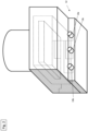
- Figure 5 shows a system S with a first, second and third machine tool 1a, 1b, 1c, each connected to a first, second and third accumulator 2a, 2b, 2c and a first, second and third charging device 22a, 22b, 22c.
- the machine tools 1a, 1b, 1c, accumulators 2a, 2b, 2c and charging devices 22a, 22b, 22c are essentially structurally identical in the present embodiment.
- system S may contain more or fewer than three machine tools, loading devices and accumulators.
- the machine tools 1a, 1b, 1c are designed as cordless screwdrivers, for example.
- the machine tools 1a, 1b, 1c can also be designed as drills, hammer drills, saws, grinders or the like.
- each machine tool 1a, 1b, 1c essentially contains a housing 3, a handle 4 and a tool holder 5. Inside the housing 3, a drive 6 in the form of an electric motor, a gear device 7, an output shaft 8, a control unit 9, a storage unit 10 and a transceiver 11 are positioned.
- the drive 6, which is designed as an electric motor, the gear device 7 and the output shaft 8 are arranged in relation to one another in such a way that a torque generated by the electric motor 6 can be transmitted to the tool holder 5 via the output shaft 8 and the gear device 7.
- the tool holder 5 is positioned at a front end 3a of the housing 3 and is used to receive and hold a tool.
- the tool can be designed as a screwdriver bit. The tool is not shown in the figures.
- the handle 4 is positioned on an underside 3b of the housing 3.
- the handle 4 is attached to the underside 3b of the housing 3 with a first end 4a.
- a machine tool interface 12 is positioned on a second end 4b of the handle 4 and is used for electrically or electronically as well as mechanically connecting the machine tool 1 to the accumulator 2.
- the machine tool 1 has a positive contact 13a, a negative contact 13b and a communication contact 13c.
- the positive and negative contacts 13a, 13b are used to generate an electrical circuit when the accumulator 2 is connected to the machine tool 1.
- the communication contact 13c is used to send and receive data and information in the form of electrical signals.
- An actuating switch 14 is provided at a front end 4c of the handle 4.
- the actuating switch 14 serves to activate the machine tool 1.
- Inside the The control unit 9 with the transceiver 11 and the storage unit 10 is positioned on the handle 4.
- the individual functions of the machine tool 1 are controlled and regulated using the control unit 9.
- the functions include, for example, setting a specific speed of the electric motor 6.
- the accumulator 2 can be detachably connected to a machine tool 1 in order to supply the machine tool 1 with electrical energy.
- Each accumulator 2 essentially contains a battery housing 15, a number of energy storage cells 16, a battery interface 17, a storage unit 18, a transceiver 19, a control device 20 and a plurality of sensors.
- the energy storage cells 16 can also be referred to as battery cells and are arranged inside the battery housing 15.
- the battery housing 15 essentially contains a cover element 15a, four side walls 15b and a base element 15c.
- the battery interface 17 is arranged on the outside of the cover element 15a and serves for the electrical or electronic as well as mechanical connection of the battery 2 to the machine tool 1 or a charging device 22.
- the battery interface 17 has a positive contact 17a, a negative contact 17b and a communication contact 17c.
- the positive and negative contacts 17a, 17b are used to generate an electrical circuit when the battery 2 is connected to a machine tool 1 or a charging device 22.
- the communication contact 17c is used to send and receive data and information in the form of electrical signals.
- the accumulator 2 can also contain radio communication (e.g. Bluetooth) or wireless communication.
- radio communication e.g. Bluetooth
- wireless communication e.g.
- the energy storage cells 16 are used to absorb, store and release electrical energy. As indicated in the figures, the energy storage cells 16 are cylindrical in shape and are designed based on lithium-ion technology. Each energy storage cell 16 contains a contact device at one end which is used to transmit electrical energy. The individual contact devices are connected to the control device 20 of the accumulator 2 via corresponding lines.
- the energy storage cells 16 may also be based on another suitable technology.
- the cylindrical shape of the energy storage cells 16 is also optional, so that any other suitable shape or geometry can be selected.
- the energy storage cells it is also possible for the energy storage cells to be designed as pouch cells.
- the accumulator 2 may contain both cylindrical energy storage cells and pouch cells. In particular, it is possible for the accumulator 2 to contain only a single cylindrical energy storage cell 16 and a single pouch cell.
- the control device 20 regulates and controls various functions of the accumulator 2.
- the functions include, among others, the control of the absorption and release of electrical energy into and from the energy storage cells 16.
- the control device 20 is used to control the amount of electrical energy that is to be absorbed or released by the energy storage cells 16.
- a first control parameter set is stored in the storage unit 18, which contains a large number of control parameters.
- the control parameters can also be referred to as control parameters or setting parameters.
- the storage unit 18 is connected to the control device 20 in such a way that the control device 20 can access the individual control parameters stored in the storage unit 18 and the functions of the accumulator 2 can be controlled or regulated using these control parameters.
- the control parameters include maximum discharge currents (current value), maximum charging currents (current value), minimum and maximum charging times, minimum and maximum internal resistances and minimum and maximum capacity values (in Ah).
- the control parameters also include methods for reducing or completely blocking the energy absorption or release by the energy storage cells 16 in the event of a maximum acceleration value or braking value, a predetermined number of braking values within predetermined threshold values, and minimum and maximum temperature values.
- the accumulator 2 also contains a sensor for recording operating parameters.
- the operating parameters can also be referred to as operating parameters, operating characteristics or operating variables.
- the accumulator 2 contains a sensor for detecting a charging current and a discharging current 30, a sensor for detecting a charging time 31, a sensor for detecting an acceleration value and braking value 32, a sensor for detecting temperature values 33, a sensor for detecting internal resistance values 34, a sensor for detecting the capacity 35 and a counter 36 for the number of acceleration values that exceed a predetermined threshold.
- the sensor for detecting a charging time 31 can also be called a clock or real-time clock.
- the acceleration value can be referred to as the value for positive acceleration and the braking value can also be referred to as the value for negative acceleration.
- the sensor for detecting temperature values 33 can also be called a thermometer or temperature meter.
- the sensor for detecting internal resistance values 34 can also be called an ohmmeter.
- the capacity sensor 35 can also be called the ampere-hour (Ah) sensor.
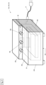
- a charging device 22 which essentially contains a charger housing 23, a control unit 24, a transceiver 25, a storage unit 26 and a power supply 27.
- the charger housing 23 essentially contains a cover element 23a, four side walls 23b and a base element 23c.
- a charger interface 28 is positioned on the cover element 23a and is used for electrically or electronically as well as mechanically connecting the charging device 22 to the accumulator 2.
- the charger interface 28 has a positive contact 28a, a negative contact 28b and a communication contact 28c.
- the positive and negative contacts 28a, 28b are used to generate an electrical circuit when the accumulator 2 is connected to the charging device 22.
- the communication contact 28c is used to send and receive data and information in the form of electrical signals.
- the charging device 22 can also contain radio communication (e.g. Bluetooth) or wireless communication.
- radio communication e.g. Bluetooth
- wireless communication e.g.
- the power supply 27 is designed in the form of a power cable for connection to a mains power source (i.e. socket), not shown.
- the control unit 24, the transceiver 25 and the storage unit 26 are positioned inside the charger housing 23.
- the control unit 24 controls and regulates the individual functions of the charging device 22. These functions include, among others, the setting of a charging current (ie the current intensity value) when a battery 2 is to be charged with the Charging device 22 is detachably connected.
- the transceiver 25 is used to send and receive data and information in the form of electrical signals.
- the charging device 22 is designed in particular to exchange data and information with a data storage and computing device 29.
- the data storage and computing device 29 contains a transceiver 37, a computing unit 38 and a storage unit 39.
- the data storage and computing device 29 can also be referred to as a cloud or cloud computer.
- the accumulator 2 is first connected to the machine tool 1 so that electrical energy can reach the consumers of the machine tool 1 from the energy storage cell 16, cf.
- Figure 1 The respective interfaces of the accumulator 2 and the machine tool 1 are detachably connected to one another. By connecting the accumulator 2 to the machine tool 1, data and information in the form of electrical signals can also be exchanged between the accumulator 2 and the machine tool 1.
- the respective transceivers 19, 25 and the interconnected communication contacts 13c, 17c of the accumulator 2 and the machine tool 1 are used to send and receive the electrical signals.
- the sensors of the accumulator 2 detect the various operating characteristics mentioned above. It is possible that only a part of the sensors detect data.
- the operating characteristics detected by the sensors are stored in the storage unit.
- a battery 2 can be removed from a respective machine tool 1 and releasably connected to a charging device 22.
- the energy storage cells 16 of the battery 2 can be charged with electrical energy using the charging device.
- the first, second and third accumulators 2a, 2b, 2c are simultaneously removed from the respective machine tools 1a, 1b, 1c and connected to the respective charging devices 22a, 22b, 22c.
- the accumulators 2a, 2b, 2c are not simultaneously removed from the machine tools and the charging devices.
- the removal of the individual accumulators 2a, 2b, 2c from the machine tools 1a, 1b, 1c and the connection of the individual accumulators 2a, 2b, 2c to the respective charging devices 22a, 22b, 22c can be done for each accumulator 2a, 2b, 2c separately, so that the removal of all accumulators 2a, 2b, 2c from the machine tools 1a, 1b, 1c and the connection to the loading devices 22a, 22b, 22c within a certain period of time.
- the period of time can be several hours or days.
- a battery 2a, 2b, 2c may be alternately connected to different charging devices 22a, 22b, 22c.
- the respective interfaces of the accumulator 2a, 2b, 2c and the charging device 22a, 22b, 22c are releasably connected to one another so that the respective communication contacts 17c, 28c of the accumulator 2 and the charging device 22 are in contact with one another.
- the respective transceivers 19, 25 of the accumulator 2 and the charging device 22 are used to send and receive the electrical signals.
- the accumulator 2 Before the actual charging process begins, i.e. before electrical energy reaches the energy storage cells 16 of the accumulator 2 from the charging device 22, the accumulator 2 sends the operating parameters stored in the storage unit 18 to the charging device 22 using the transceivers 19, 25 and communication contacts 17c, 28c.
- the charging device 22 stores the received operating characteristic values in the storage unit 26 of the charging device 22.
- the operating characteristics are sent to the data storage and computing device 29.
- Each charging device 22 sends received operating characteristics to the data storage and computing device 29 as soon as the corresponding charging device 22 is connected to the data storage and computing device 29.
- the data storage and computing device 29 stores threshold values for the corresponding operating parameters which are detected by the sensors of the accumulator 2.
- control parameters as well as complete control parameter sets for a large number of different accumulators 2 are stored in the data storage and computing device 29.
- a predetermined amount of operating characteristics of the same category is collected for a predetermined period of time.
- the collection of Operating parameters of the same category within a certain period of time serves to provide the most comprehensive possible representation of the respective operating states of all accumulators 2a, 2b, 2c belonging to system S.
- the predetermined period of time can be hours or days.
- the predetermined amount or number of operating parameters can be dozens or even hundreds of operating parameters of the same category.
- the collected operating parameters are compared with the respective threshold values in the data storage and computing device 29. If an operating parameter of a category exceeds a corresponding threshold value for the predetermined period of time and for the predetermined amount or number, a new control parameter is sent from the data storage and computing device 29 to all charging devices 22a, 22b, 22c.
- the new control parameter is then sent from the charging device 22a, 22b, 22c to the respective connected accumulator 2a, 2b, 2c. It is also possible for the new control parameter to be stored in the charging device 22a, 22b, 22c and sent to different accumulators 2a, 2b, 2c that are subsequently connected to the charging device 22a, 22b, 22c.
- the received new control parameter is used to replace a corresponding control parameter.
- This corresponding control parameter can also be referred to as the previous or old control parameter.
- more than one new control parameter may also be sent from the data storage and computing device 29 to the charging device 22a, 22b, 22c if more than one operating characteristic exceeds the corresponding threshold values. It is also possible for one or more new control parameters to be sent from the data storage and computing device 29 to the charging device 22a, 22b, 22c if one or more recorded operating characteristic values do not yet exceed corresponding threshold values, but the recorded operating characteristic values only correspond to these threshold values.
- a completely new set of control parameters is sent from the data storage and computing device 29 to the charging device 22a, 22b, 22c and finally to the accumulator 2a, 2b, 2c.
- the complete The new control parameter set serves to replace the existing control parameter set in the accumulator 2a, 2b, 2c.
Landscapes
- Engineering & Computer Science (AREA)
- Power Engineering (AREA)
- Charge And Discharge Circuits For Batteries Or The Like (AREA)
- Secondary Cells (AREA)
Priority Applications (3)
| Application Number | Priority Date | Filing Date | Title |
|---|---|---|---|
| EP23190256.0A EP4507155A1 (fr) | 2023-08-08 | 2023-08-08 | Régulation adaptative pour un ensemble d'accumulateurs |
| CN202480040099.XA CN121368852A (zh) | 2023-08-08 | 2024-07-22 | 可充电电池的组合的自适应调节 |
| PCT/EP2024/070708 WO2025031772A1 (fr) | 2023-08-08 | 2024-07-22 | Commande adaptative pour une combinaison de batteries de stockage |
Applications Claiming Priority (1)
| Application Number | Priority Date | Filing Date | Title |
|---|---|---|---|
| EP23190256.0A EP4507155A1 (fr) | 2023-08-08 | 2023-08-08 | Régulation adaptative pour un ensemble d'accumulateurs |
Publications (1)
| Publication Number | Publication Date |
|---|---|
| EP4507155A1 true EP4507155A1 (fr) | 2025-02-12 |
Family
ID=87567783
Family Applications (1)
| Application Number | Title | Priority Date | Filing Date |
|---|---|---|---|
| EP23190256.0A Withdrawn EP4507155A1 (fr) | 2023-08-08 | 2023-08-08 | Régulation adaptative pour un ensemble d'accumulateurs |
Country Status (3)
| Country | Link |
|---|---|
| EP (1) | EP4507155A1 (fr) |
| CN (1) | CN121368852A (fr) |
| WO (1) | WO2025031772A1 (fr) |
Citations (3)
| Publication number | Priority date | Publication date | Assignee | Title |
|---|---|---|---|---|
| EP3687024A1 (fr) * | 2018-01-26 | 2020-07-29 | TTI (Macao Commercial Offshore) Limited | Appareil électrique, système d'alimentation, outil électrique, réseau d'outils électriques et organe de commande d'outils électriques |
| US20220102995A1 (en) * | 2020-09-29 | 2022-03-31 | Milwaukee Electric Tool Corporation | Universal wireless charging of power tool battery packs |
| WO2023076387A2 (fr) * | 2021-10-27 | 2023-05-04 | Milwaukee Electric Tool Corporation | Chargeur de batterie d'outil électrique intelligent |
-
2023
- 2023-08-08 EP EP23190256.0A patent/EP4507155A1/fr not_active Withdrawn
-
2024
- 2024-07-22 CN CN202480040099.XA patent/CN121368852A/zh active Pending
- 2024-07-22 WO PCT/EP2024/070708 patent/WO2025031772A1/fr active Pending
Patent Citations (3)
| Publication number | Priority date | Publication date | Assignee | Title |
|---|---|---|---|---|
| EP3687024A1 (fr) * | 2018-01-26 | 2020-07-29 | TTI (Macao Commercial Offshore) Limited | Appareil électrique, système d'alimentation, outil électrique, réseau d'outils électriques et organe de commande d'outils électriques |
| US20220102995A1 (en) * | 2020-09-29 | 2022-03-31 | Milwaukee Electric Tool Corporation | Universal wireless charging of power tool battery packs |
| WO2023076387A2 (fr) * | 2021-10-27 | 2023-05-04 | Milwaukee Electric Tool Corporation | Chargeur de batterie d'outil électrique intelligent |
Also Published As
| Publication number | Publication date |
|---|---|
| CN121368852A (zh) | 2026-01-20 |
| WO2025031772A1 (fr) | 2025-02-13 |
Similar Documents
| Publication | Publication Date | Title |
|---|---|---|
| EP3679623B1 (fr) | Procédé de commande d'un accumulateur d'une machine-outil | |
| WO2021063740A1 (fr) | Procédé de décharge efficace d'une batterie rechargeable | |
| WO2023083651A1 (fr) | Procédé pour charger ou décharger un accumulateur d'énergie interchangeable au moyen d'un dispositif électrique et système comprenant un accumulateur d'énergie interchangeable et dispositif électrique pour la mise en œuvre du procédé | |
| WO2023083624A1 (fr) | Établissement d'une connexion pour une communication entre un premier et un second composant de système | |
| EP4507155A1 (fr) | Régulation adaptative pour un ensemble d'accumulateurs | |
| EP4507156A1 (fr) | Commande adaptative pour un ensemble de batteries et de machines-outils | |
| EP4507154A1 (fr) | Commande adaptative pour batteries | |
| EP3659202B1 (fr) | Circuit de dérivation sur un accumulateur | |
| EP4486540A1 (fr) | Machine-outil à batterie rechargeable intégrée | |
| WO2024002689A1 (fr) | Commande en boucle ouverte et commande en boucle fermée d'un système au moyen d'un jumeau numérique d'une batterie rechargeable | |
| WO2016046246A1 (fr) | Extrémité de charge intelligente | |
| EP4137831A1 (fr) | Procédé de détermination de l'état de santé d'un accumulateur | |
| DE102020212769B4 (de) | Verfahren zum unterbrechungsfreien Betreiben eines netzunabhängig betriebenen mobilen Systems und mobiles System | |
| WO2023020849A1 (fr) | Procédé de charge rapide d'une batterie rechargeable | |
| EP4369551A1 (fr) | Routine de charge optimisée pour accumulateur | |
| EP4239830A1 (fr) | Accumulateur pourvu de deux dispositifs interfaces | |
| EP4651365A1 (fr) | Réglage de la fréquence pwm sur la base des caractéristiques du système | |
| EP4576485A1 (fr) | Surveillance du système de machines-outils fonctionnant sur batterie | |
| EP4601157A1 (fr) | Adaptateur pour un dispositif de charge multiple | |
| EP4485741A1 (fr) | Système d'accumulation d'énergie pour une machine-outil, procédé de détermination d'une statistique d'état d'un accumulateur d'énergie d'un système d'accumulation d'énergie et machine-outil | |
| EP4418488A1 (fr) | Système de charge, de refroidissement et de chauffage d'accumulateurs | |
| EP4137830A1 (fr) | Procédé de détermination de la capacité d'un accumulateur | |
| DE102021200936A1 (de) | Adaptervorrichtung |
Legal Events
| Date | Code | Title | Description |
|---|---|---|---|
| PUAI | Public reference made under article 153(3) epc to a published international application that has entered the european phase |
Free format text: ORIGINAL CODE: 0009012 |
|
| STAA | Information on the status of an ep patent application or granted ep patent |
Free format text: STATUS: THE APPLICATION HAS BEEN PUBLISHED |
|
| AK | Designated contracting states |
Kind code of ref document: A1 Designated state(s): AL AT BE BG CH CY CZ DE DK EE ES FI FR GB GR HR HU IE IS IT LI LT LU LV MC ME MK MT NL NO PL PT RO RS SE SI SK SM TR |
|
| STAA | Information on the status of an ep patent application or granted ep patent |
Free format text: STATUS: THE APPLICATION IS DEEMED TO BE WITHDRAWN |
|
| 18D | Application deemed to be withdrawn |
Effective date: 20250813 |